1
/
of
8
www.ChineseStandard.us -- Field Test Asia Pte. Ltd.
GB/T 4315.2-2009 English PDF (GB/T4315.2-2009)
GB/T 4315.2-2009 English PDF (GB/T4315.2-2009)
Regular price
$330.00
Regular price
Sale price
$330.00
Unit price
/
per
Shipping calculated at checkout.
Couldn't load pickup availability
GB/T 4315.2-2009: Optical transfer function -- Part 2: Directives of measurement
Delivery: 9 seconds. Download (& Email) true-PDF + Invoice.
Get Quotation: Click GB/T 4315.2-2009 (Self-service in 1-minute)
Historical versions (Master-website): GB/T 4315.2-2009
Preview True-PDF (Reload/Scroll-down if blank)
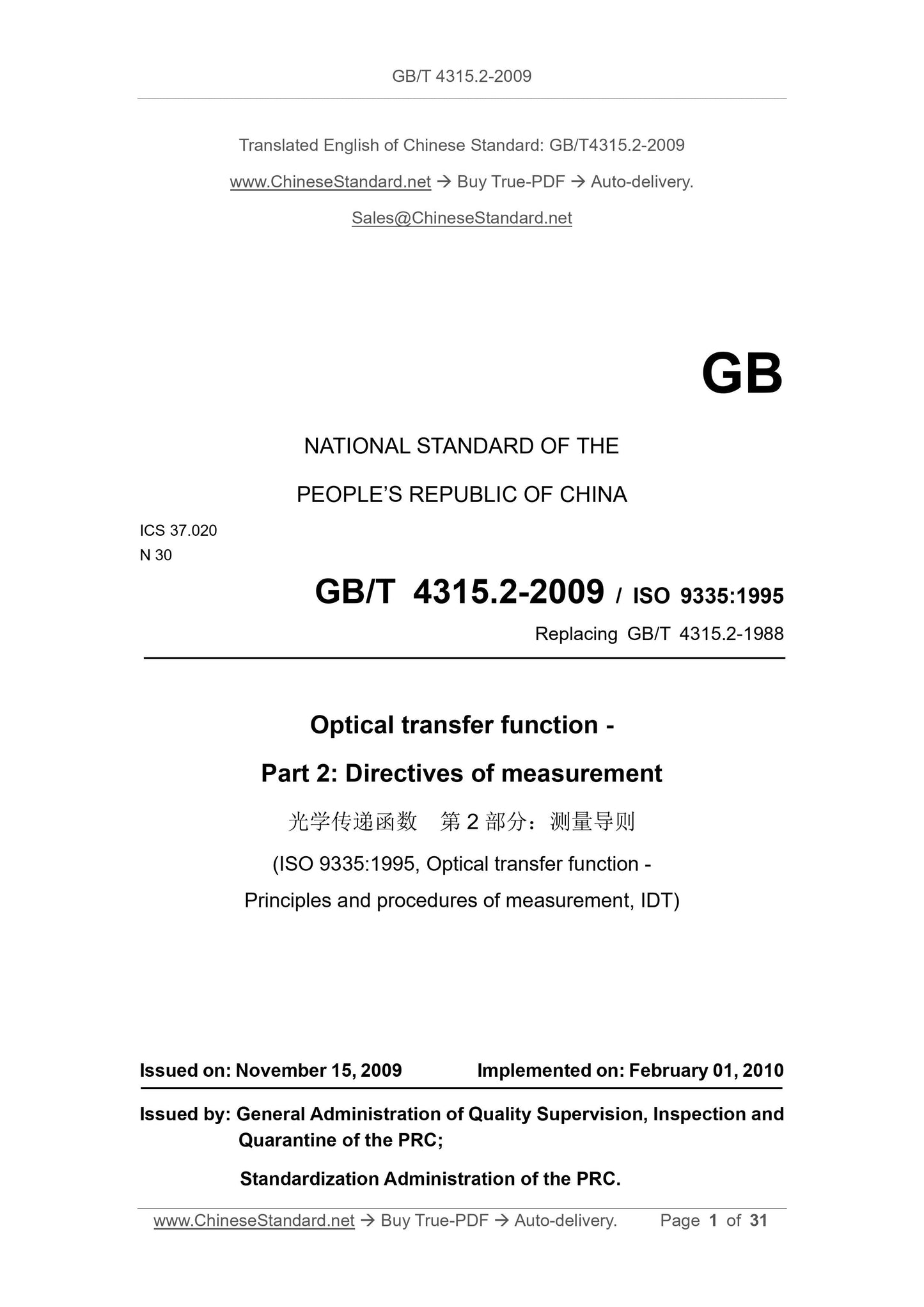
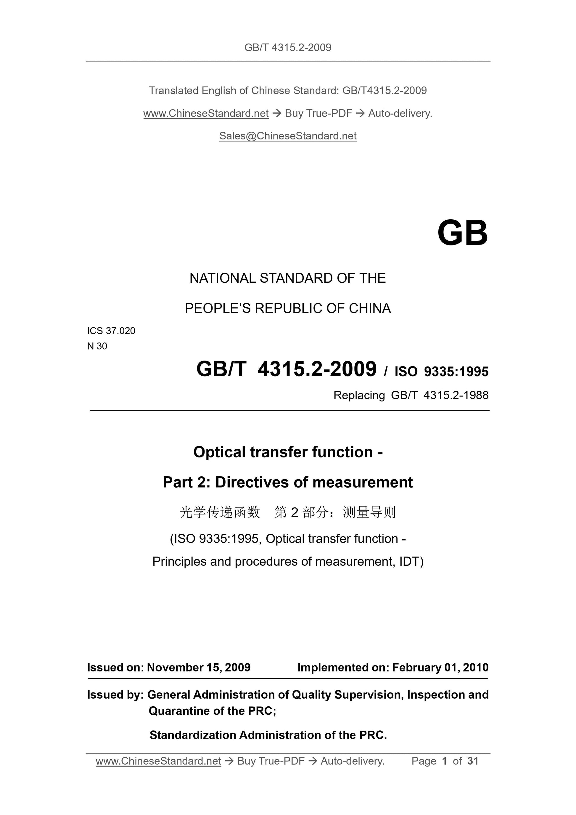
GB/T 4315.2-2009
GB
NATIONAL STANDARD OF THE
PEOPLE’S REPUBLIC OF CHINA
ICS 37.020
N 30
GB/T 4315.2-2009 / ISO 9335:1995
Replacing GB/T 4315.2-1988
Optical transfer function -
Part 2: Directives of measurement
(ISO 9335:1995, Optical transfer function -
Principles and procedures of measurement, IDT)
ISSUED ON: NOVEMBER 15, 2009
IMPLEMENTED ON: FEBRUARY 01, 2010
Issued by: General Administration of Quality Supervision, Inspection and
Quarantine of the PRC;
Standardization Administration of the PRC.
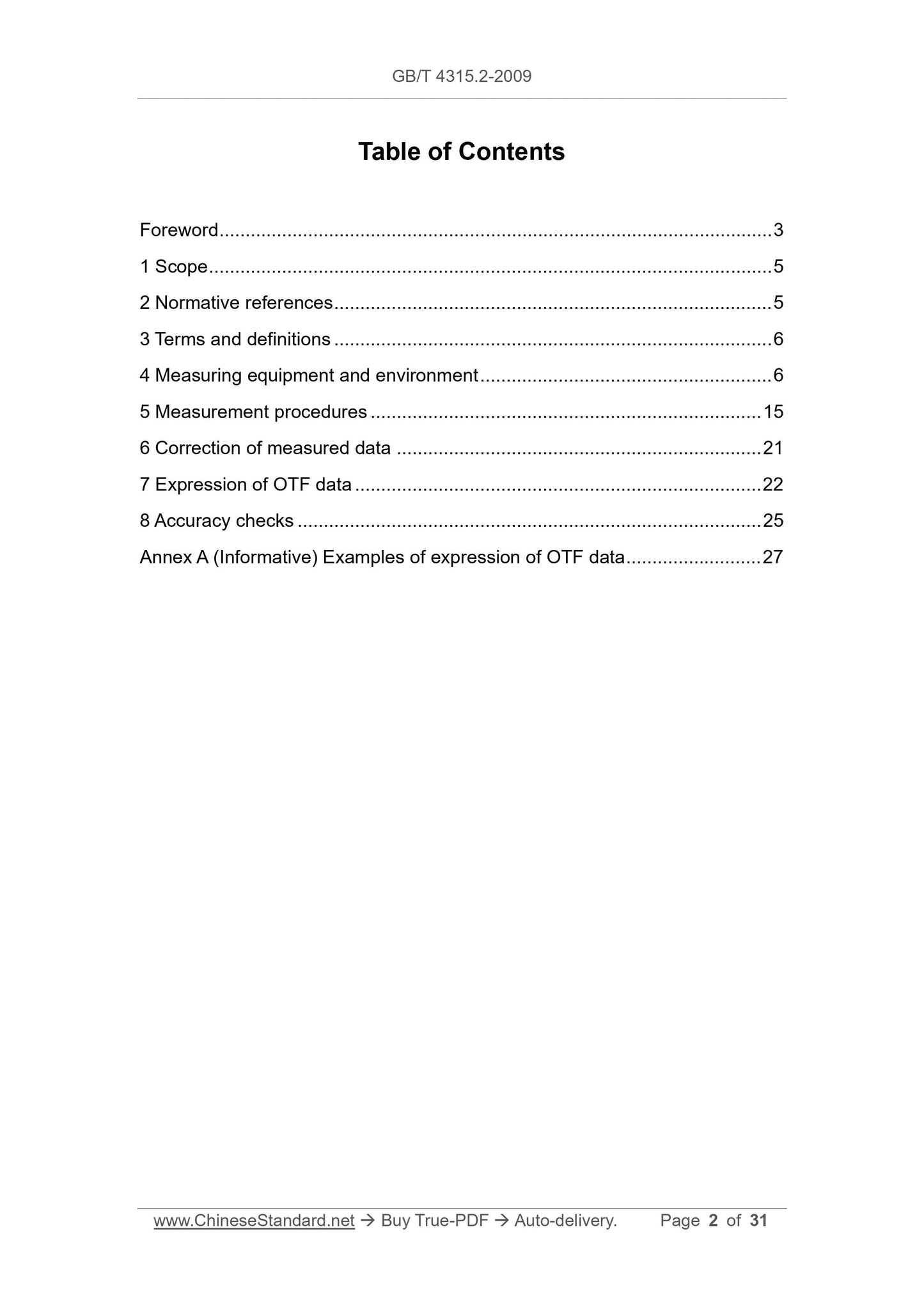
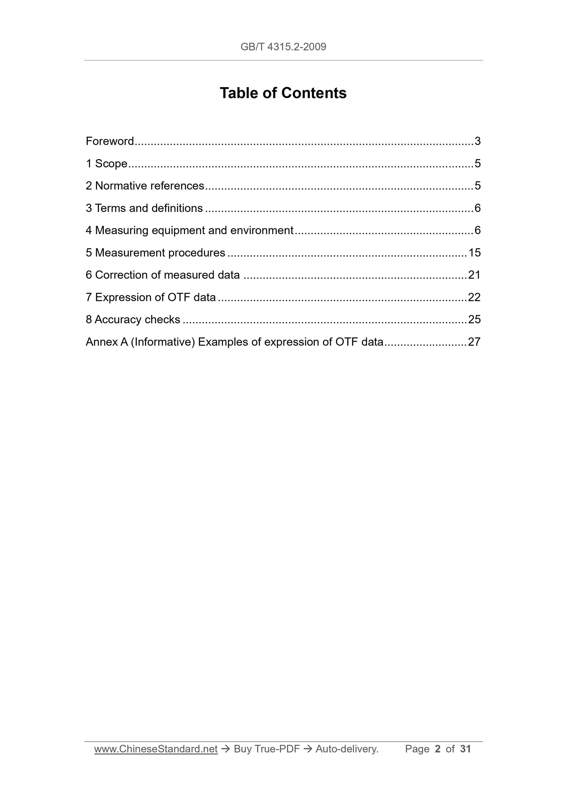
Table of Contents
Foreword ... 3
1 Scope ... 5
2 Normative references ... 5
3 Terms and definitions ... 6
4 Measuring equipment and environment ... 6
5 Measurement procedures ... 15
6 Correction of measured data ... 21
7 Expression of OTF data ... 22
8 Accuracy checks ... 25
Annex A (Informative) Examples of expression of OTF data ... 27
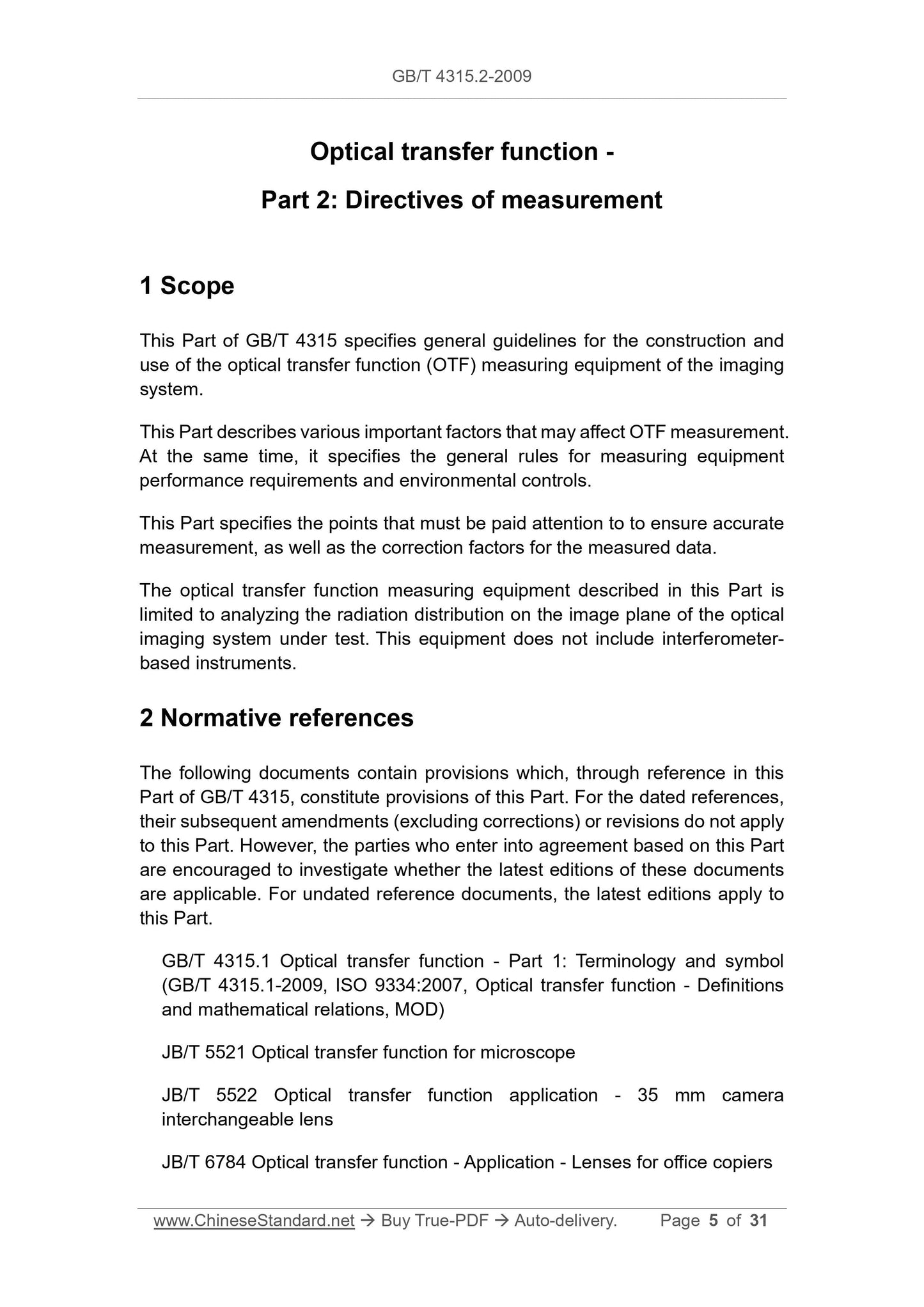
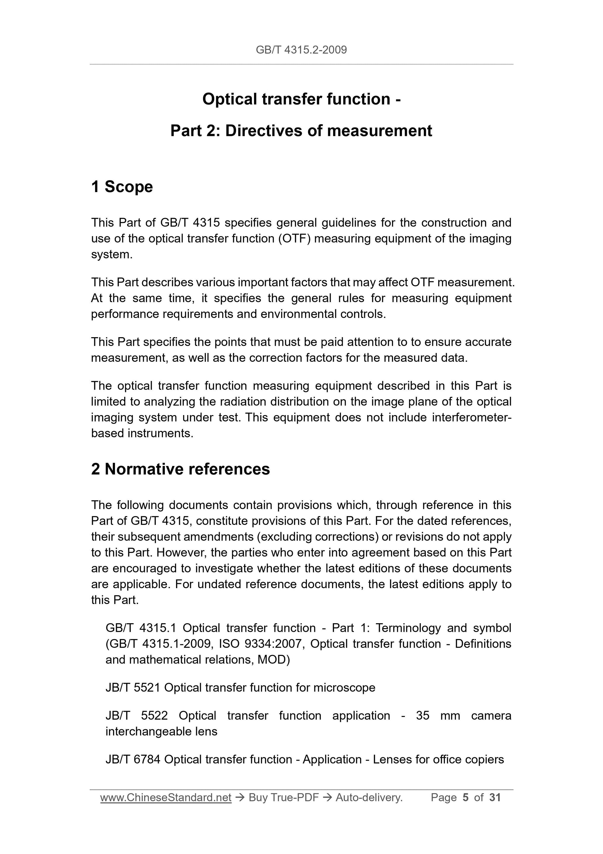
Optical transfer function -
Part 2: Directives of measurement
1 Scope
This Part of GB/T 4315 specifies general guidelines for the construction and
use of the optical transfer function (OTF) measuring equipment of the imaging
system.
This Part describes various important factors that may affect OTF measurement.
At the same time, it specifies the general rules for measuring equipment
performance requirements and environmental controls.
This Part specifies the points that must be paid attention to to ensure accurate
measurement, as well as the correction factors for the measured data.
The optical transfer function measuring equipment described in this Part is
limited to analyzing the radiation distribution on the image plane of the optical
imaging system under test. This equipment does not include interferometer-
based instruments.
2 Normative references
The following documents contain provisions which, through reference in this
Part of GB/T 4315, constitute provisions of this Part. For the dated references,
their subsequent amendments (excluding corrections) or revisions do not apply
to this Part. However, the parties who enter into agreement based on this Part
are encouraged to investigate whether the latest editions of these documents
are applicable. For undated reference documents, the latest editions apply to
this Part.
GB/T 4315.1 Optical transfer function - Part 1: Terminology and symbol
(GB/T 4315.1-2009, ISO 9334:2007, Optical transfer function - Definitions
and mathematical relations, MOD)
JB/T 5521 Optical transfer function for microscope
JB/T 5522 Optical transfer function application - 35 mm camera
interchangeable lens
JB/T 6784 Optical transfer function - Application - Lenses for office copiers
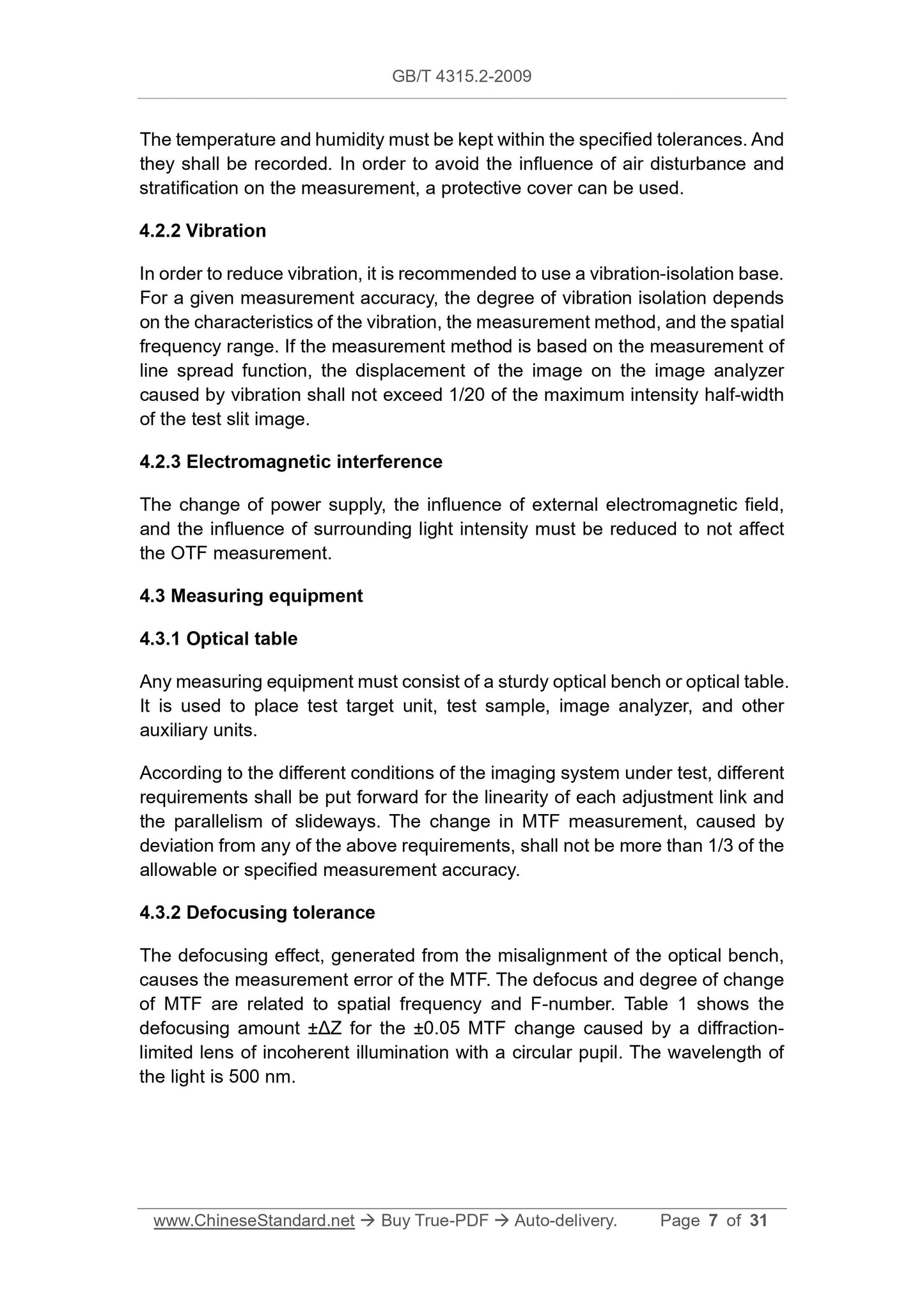
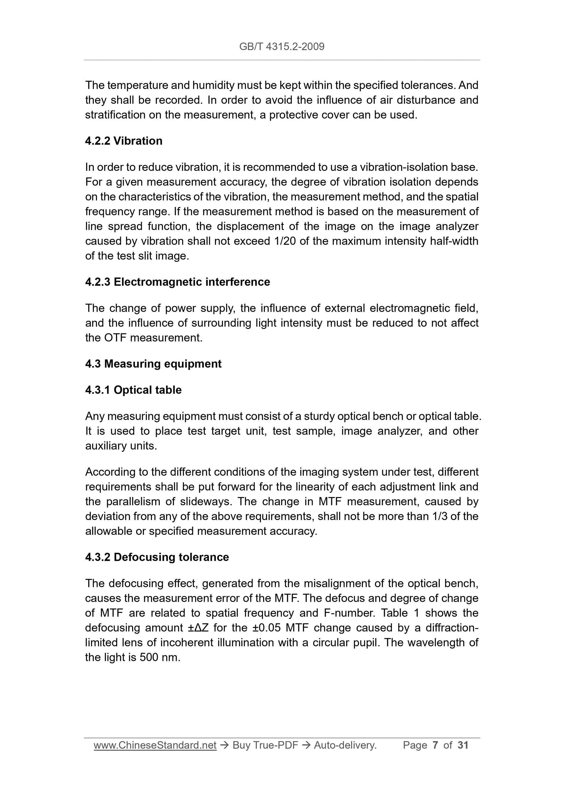
The temperature and humidity must be kept within the specified tolerances. And
they shall be recorded. In order to avoid the influence of air disturbance and
stratification on the measurement, a protective cover can be used.
4.2.2 Vibration
In order to reduce vibration, it is recommended to use a vibration-isolation base.
For a given measurement accuracy, the degree of vibration isolation depends
on the characteristics of the vibration, the measurement method, and the spatial
frequency range. If the measurement method is based on the measurement of
line spread function, the displacement of the image on the image analyzer
caused by vibration shall not exceed 1/20 of the maximum intensity half-width
of the test slit image.
4.2.3 Electromagnetic interference
The change of power supply, the influence of external electromagnetic field,
and the influence of surrounding light intensity must be reduced to not affect
the OTF measurement.
4.3 Measuring equipment
4.3.1 Optical table
Any measuring equipment must consist of a sturdy optical bench or optical table.
It is used to place test target unit, test sample, image analyzer, and other
auxiliary units.
According to the different conditions of the imaging system under test, different
requirements shall be put forward for the linearity of each adjustment link and
the parallelism of slideways. The change in MTF measurement, caused by
deviation from any of the above requirements, shall not be more than 1/3 of the
allowable or specified measurement accuracy.
4.3.2 Defocusing tolerance
The defocusing effect, generated from the misalignment of the optical bench,
causes the measurement error of the MTF. The defocus and degree of change
of MTF are related to spatial frequency and F-number. Table 1 shows the
defocusing amount ±ΔZ for the ±0.05 MTF change caused by a diffraction-
limited lens of incoherent illumination with a circular pupil. The wavelength of
the light is 500 nm.
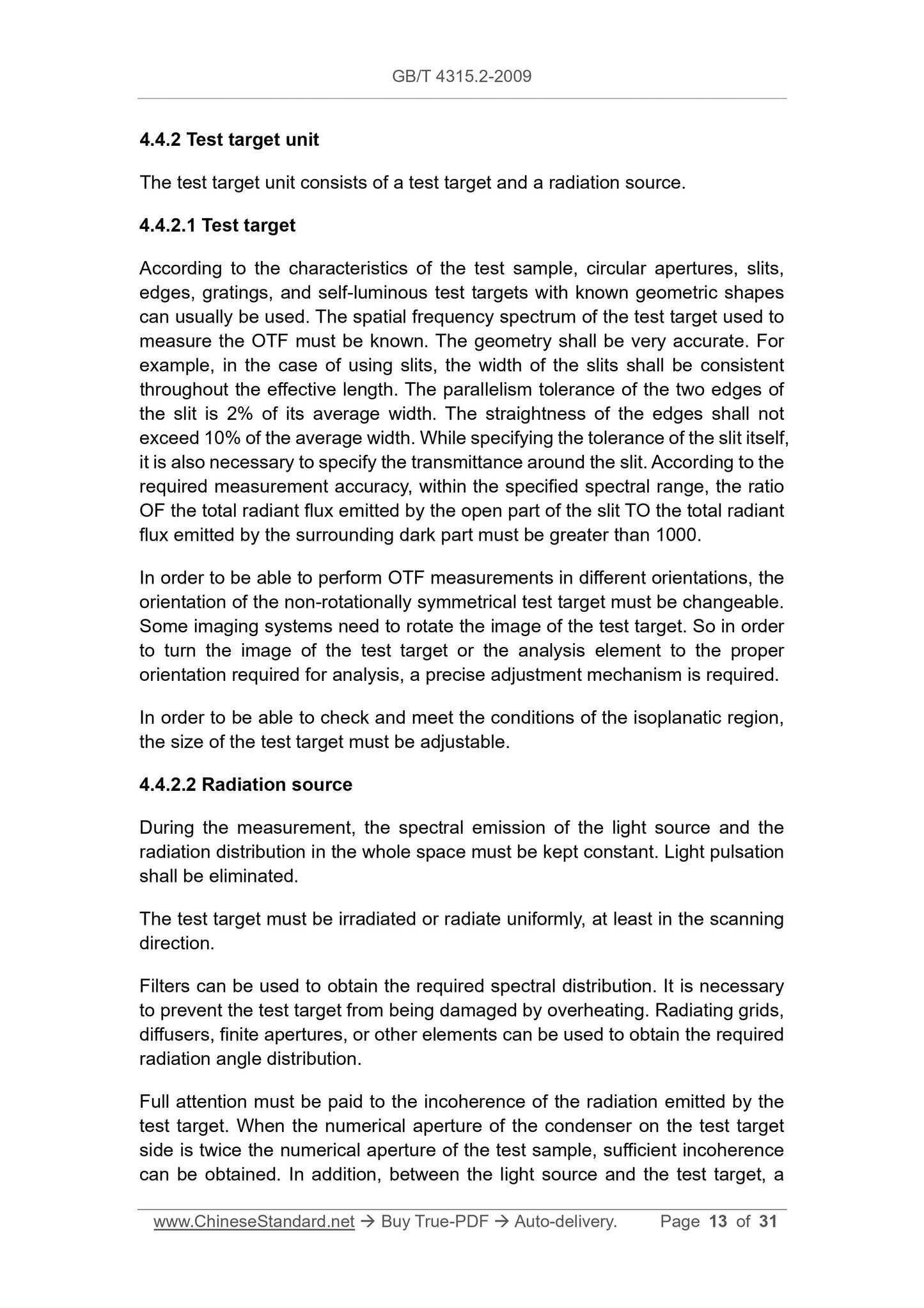
4.4.2 Test target unit
The test target unit consists of a test target and a radiation source.
4.4.2.1 Test target
According to the characteristics of the test sample, circular apertures, slits,
edges, gratings, and self-luminous test targets with known geometric shapes
can usually be used. The spatial frequency spectrum of the test target used to
measure the OTF must be known. The geometry shall be very accurate. For
example, in the case of using slits, the width of the slits shall be consistent
throughout the effective length. The parallelism tolerance of the two edges of
the slit is 2% of its average width. The straightness of the edges shall not
exceed 10% of the average width. While specifying the tolerance of the slit itself,
it is also necessary to specify the transmittance around the slit. According to the
required measurement accuracy, within the specified spectral range, the ratio
OF the total radiant flux emitted by the open part of the slit TO the total radiant
flux emitted by the surrounding dark part must be greater than 1000.
In order to be able to perform OTF measurements in different orientations, the
orientation of the non-rotationally symmetrical test target must be changeable.
Some imaging systems need to rotate the image of the test target. So in order
to turn the image of the test target or the analysis element to the proper
orientation required for analysis, a precise adjustment mechanism is required.
In order to be able to check and meet the conditions of the isoplanatic region,
the size of the test target must be adjustable.
4.4.2.2 Radiation source
During the measurement, the spectral emission of the light source and the
radiation distribution in the whole space must be kept constant. Light pulsation
shall be eliminated.
The test target must be irradiated or radiate uniformly, at least in the scanning
direction.
Filters can be used to obtain the required spectral distribution. It is necessary
to prevent the test target from being damaged by overheating. Radiating grids,
diffusers, finite apertures, or other elements can be used to obtain the required
radiation angle distribution.
Full attention must be paid to the incoherence of the radiation emitted by the
test target. When the numerical aperture of the condenser on the test target
side is twice the numerical aperture of the test sample, sufficient incoherence
can be obtained. In addition, between the light source and the test target, a
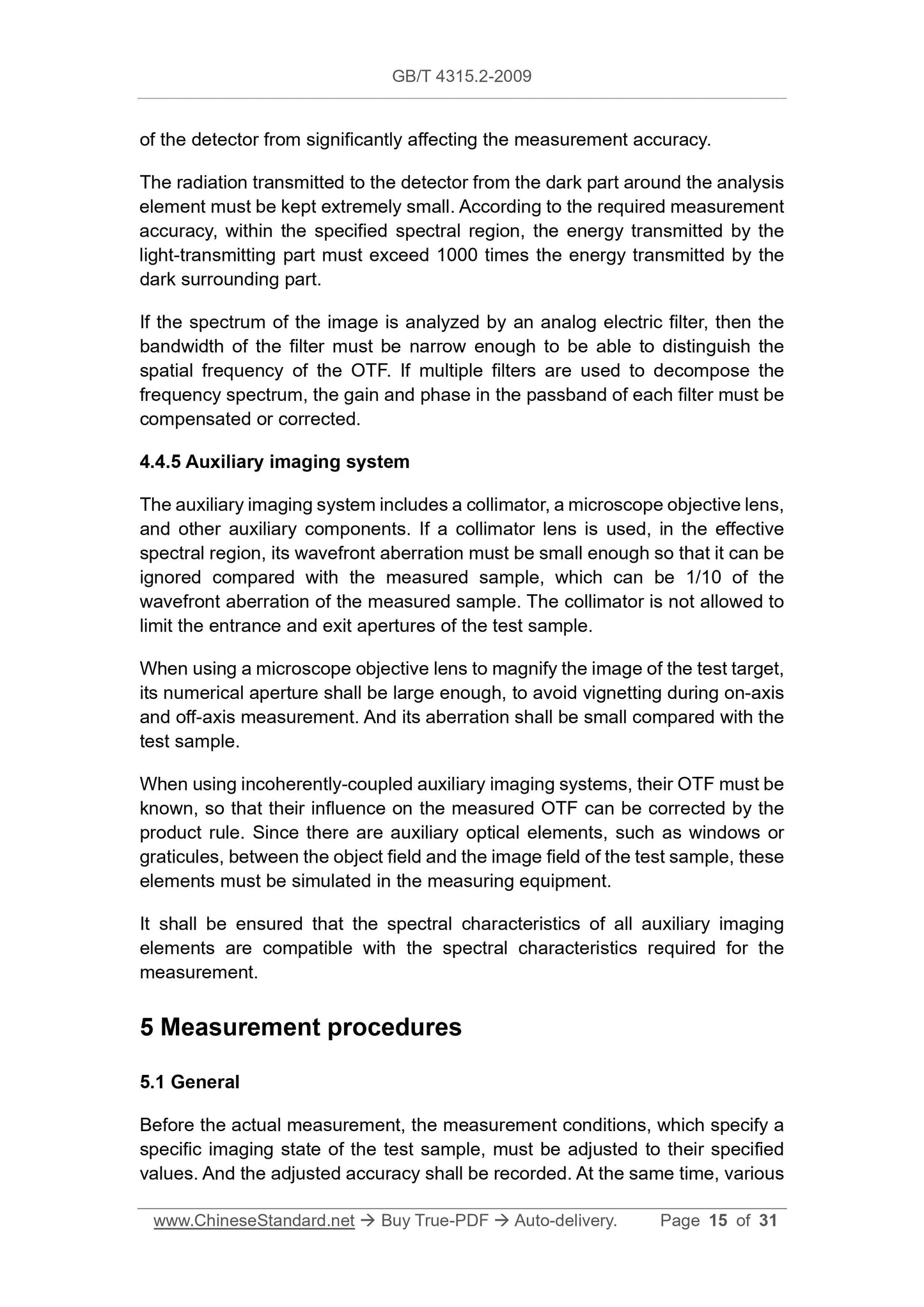
of the detector from significantly affecting the measurement accuracy.
The radiation transmitted to the detector from the dark part around the analysis
element must be kept extremely small. According to the required measurement
accuracy, within the specified spectral region, the energy transmitted by the
light-transmitting part must exceed 1000 times the energy transmitted by the
dark surrounding part.
If the spectrum of the image is analyzed by an analog electric filter, then the
bandwidth of the filter must be narrow enough to be able to distinguish the
spatial frequency of the OTF. If multiple filters are used to decompose the
frequency spectrum, the gain and phase in the passband of each filter must be
compensated or corrected.
4.4.5 Auxiliary imaging system
The auxiliary imaging system includes a collimator, a microscope objective lens,
and other auxiliary components. If a collimator lens is used, in the effective
spectral region, its wavefront aberration must be small enough so that it can be
ignored compared with the measured sample, which can be 1/10 of the
wavefront aberration of the measured sample. The collimator is not allowed to
limit the entrance and exit apertures of the test sample.
When using a microscope objective lens to magnify the image of the test target,
its numerical aperture shall be large enough, to avoid vignetting during on-axis
and off-axis measurement. And its aberration shall be small compared with the
test sample.
When using incoherently-coupled auxiliary imaging systems, their OTF must be
known, so that their influence on the measured OTF can be corrected by the
product rule. Since there are auxiliary optical elements, such as windows or
graticules, between the object field and the image field of the test sample, these
elements must be simulated in the measuring equipment.
It shall be ensured that the spectral characteristics of all auxiliary imaging
elements are compatible with the spectral characteristics required for the
measurement.
5 Measurement procedures
5.1 General
Before the actual measurement, the measurement conditions, which specify a
specific imaging state of the test sample, must be adjusted to their specified
values. And the adjusted accuracy shall be recorded. At the same time, various
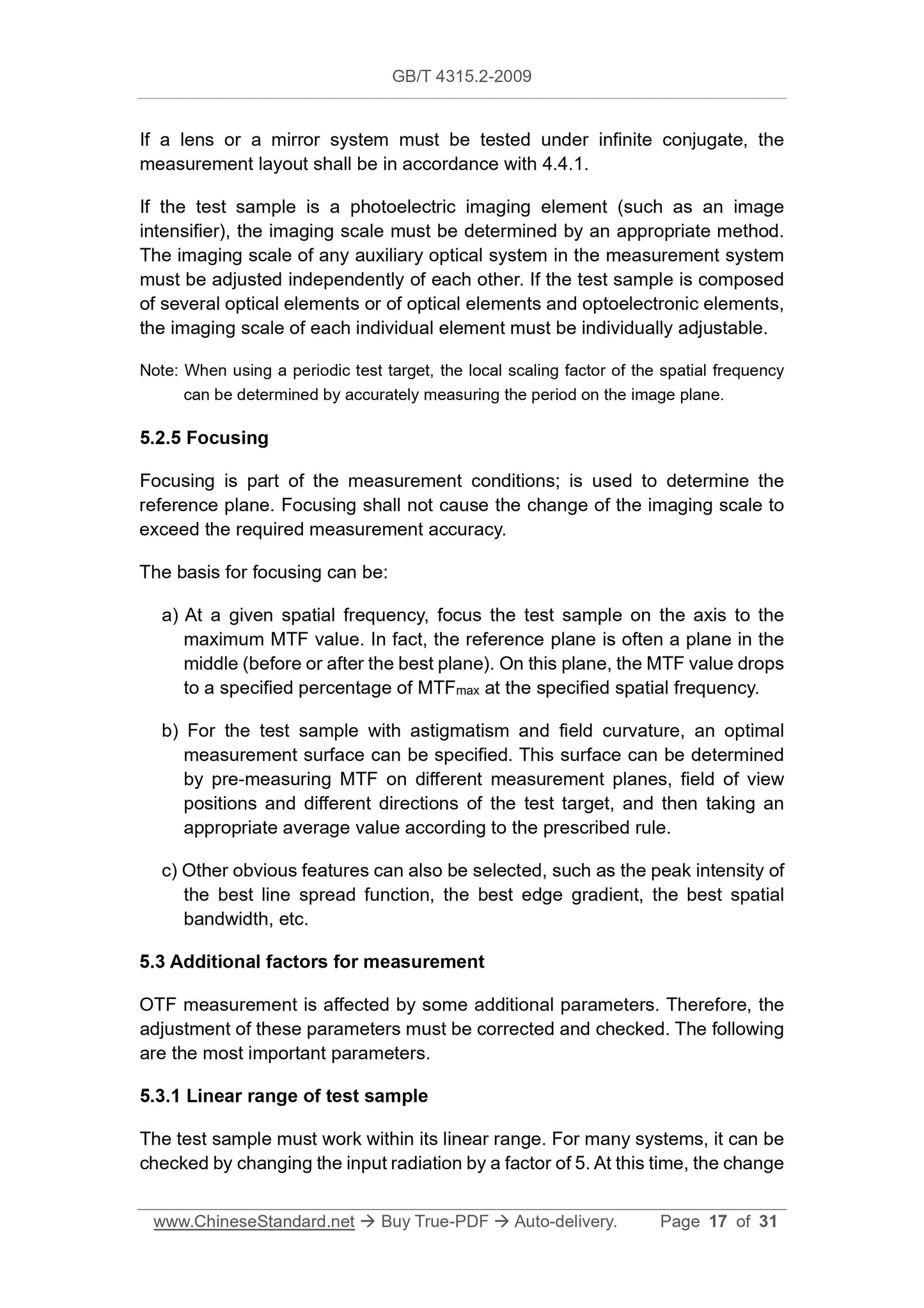
If a lens or a mirror system must be tested under infinite conjugate, the
measurement layout shall be in accordance with 4.4.1.
If the test sample is a photoelectric imaging element (such as an image
intensifier), the imaging scale must be determined by an appropriate method.
The imaging scale of any auxiliary optical system in the measurement system
must be adjusted independently of each other. If the test sample is composed
of several optical elements or of optical elements and optoelectronic elements,
the imaging scale of each individual element must be individually adjustable.
Note: When using a periodic test target, the local scaling factor of the spatial frequency
can be determined by accurately measuring the period on the image plane.
5.2.5 Focusing
Focusing is part of the measurement conditions; is used to determine the
reference plane. Focusing shall not cause the change of the imaging scale to
exceed the required measurement accuracy.
The basis for focusing can be:
a) At a given spatial frequency, focus the test sample on the axis to the
maximum MTF value. In fact, the reference plane is often a plane in the
middle (before or after the best plane). On this plane, the MTF value drops
to a specified percentage of MTFmax at the specified spatial frequency.
b) For the test sample with astigmatism and field curvature, an optimal
measurement surface can be specified. This surface can be determined
by pre-measuring MTF on different measurement planes, field of view
positions and different directions of the test target, and then taking an
appropriate average value according to the prescribed rule.
c) Other obvious features can also be selected, such as the peak intensity of
the best line spread function, the best edge gradient, the best spatial
bandwidth, etc.
5.3 Additional factors for measurement
OTF measurement is affected by some additional parameters. Therefore, the
adjustment of these parameters must be corrected and checked. The following
are the most important parameters.
5.3.1 Linear range of test sample
The test sample must work within its linear range. For many systems, it can be
checked by changing the input radiation by a factor of 5. At this time, the change
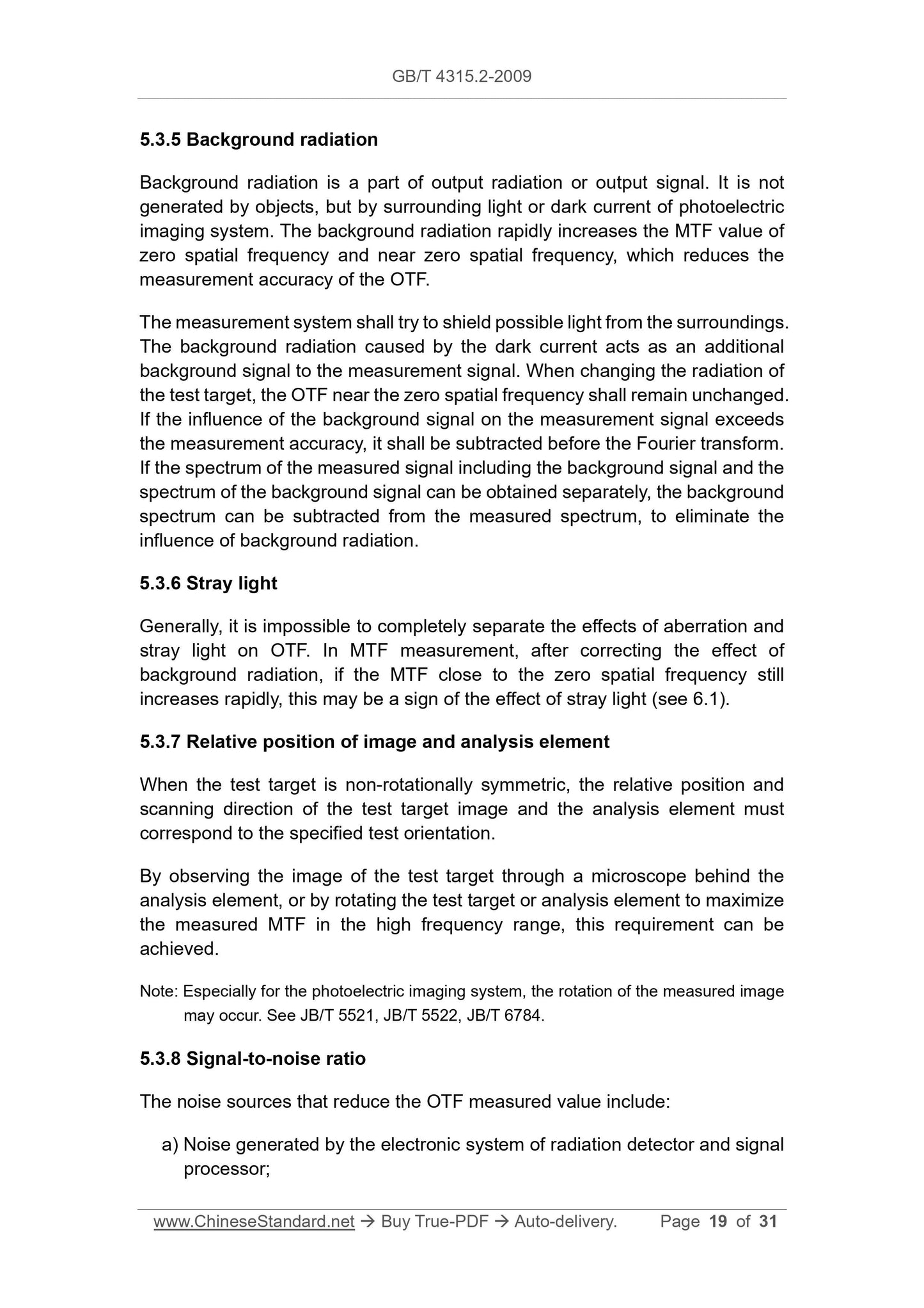
5.3.5 Background radiation
Background radiation is a part of output radiation or output signal. It is not
generated by objects, but by surrounding light or dark current of photoelectric
imaging system. The background radiation rapidly increases the MTF value of
zero spatial frequency and near zero spatial frequency, which reduces the
measurement accuracy of the OTF.
The measurement system shall try to shield possible light from the surroundings.
The background radiation caused by the dark current acts as an additional
background signal to the measurement signal. When changing the radiation of
the test target, the OTF near the zero spatial frequency shall remain unchanged.
If the influence of the background signal on the measurement signal exceeds
the measurement accuracy, it shall be subtracted before the Fourier transform.
If the spectrum of the measured signal including the background signal and the
spectrum of the background signal can be obtained separately, the background
spectrum can be subtracted from the measured spectrum, to eliminate the
influence of background radiation.
5.3.6 Stray light
Generally, it is impossible to completely separate the effects of aberration and
stray light on OTF. In MTF measurement, after correcting the effect of
background radiation, if the MTF close to the zero spatial frequency still
increases rapidly, this may be a sign of the effect of stray light (see 6.1).
5.3.7 Relative position of image and analysis element
When the test target is non-rotationally symmetric, the relative position and
scanning direction of the test target image and the analysis element must
correspond to the specified test orientation.
By observing the image of the test target through a microscope behind the
analysis element, or by rotating the test target or analysis element to maximize
the measured MTF in the high frequency range, this requirement can be
achieved.
Note: Especially for the photoelectric imaging system, the rotation of the measured image
may occur. See JB/T 5521, JB/T 5522, JB/T 6784.
5.3.8 Signal-to-noise ratio
The noise sources that reduce the OTF measured value include:
a) Noise generated by the electronic system of radiation detector and signal
processor;
GB/T 4315.2-2009
GB
NATIONAL STANDARD OF THE
PEOPLE’S REPUBLIC OF CHINA
ICS 37.020
N 30
GB/T 4315.2-2009 / ISO 9335:1...
Share
