1
/
of
9
www.ChineseStandard.us -- Field Test Asia Pte. Ltd.
GB/T 43252-2023 English PDF (GB/T43252-2023)
GB/T 43252-2023 English PDF (GB/T43252-2023)
Regular price
$320.00
Regular price
Sale price
$320.00
Unit price
/
per
Shipping calculated at checkout.
Couldn't load pickup availability
GB/T 43252-2023: Test methods of energy consumption and range for fuel cell electric vehicles
Delivery: 9 seconds. Download (& Email) true-PDF + Invoice.
Get Quotation: Click GB/T 43252-2023 (Self-service in 1-minute)
Historical versions (Master-website): GB/T 43252-2023
Preview True-PDF (Reload/Scroll-down if blank)
GB/T 43252-2023
GB
NATIONAL STANDARD OF THE
PEOPLE’S REPUBLIC OF CHINA
ICS 43.120
CCS T 47
Test methods of energy consumption and range for fuel cell
electric vehicles
ISSUED ON: NOVEMBER 27, 2023
IMPLEMENTED ON: NOVEMBER 27, 2023
Issued by: State Administration for Market Regulation;
Standardization Administration of the People’s Republic of China.
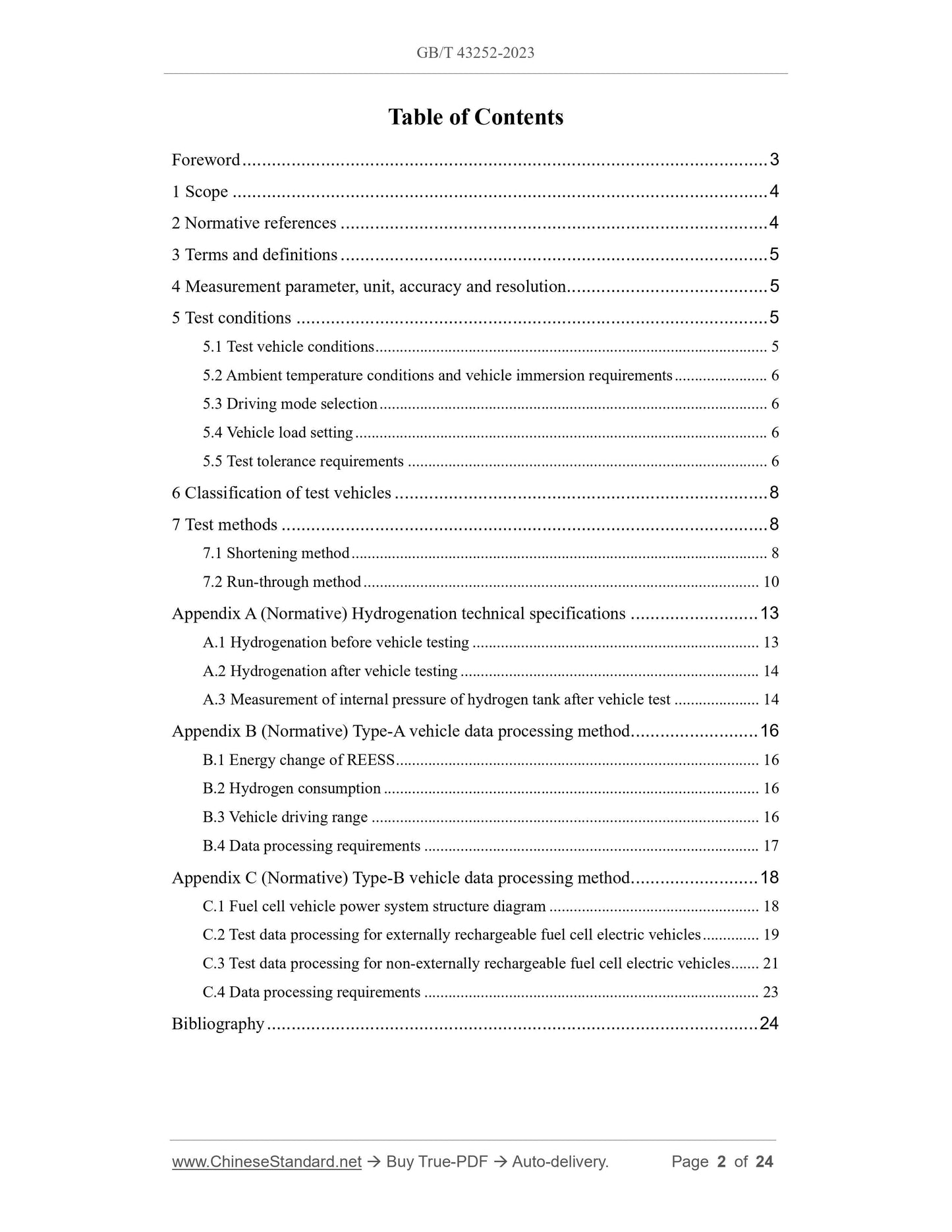
Table of Contents
Foreword ... 3
1 Scope ... 4
2 Normative references ... 4
3 Terms and definitions ... 5
4 Measurement parameter, unit, accuracy and resolution ... 5
5 Test conditions ... 5
5.1 Test vehicle conditions ... 5
5.2 Ambient temperature conditions and vehicle immersion requirements ... 6
5.3 Driving mode selection ... 6
5.4 Vehicle load setting ... 6
5.5 Test tolerance requirements ... 6
6 Classification of test vehicles ... 8
7 Test methods ... 8
7.1 Shortening method ... 8
7.2 Run-through method ... 10
Appendix A (Normative) Hydrogenation technical specifications ... 13
A.1 Hydrogenation before vehicle testing ... 13
A.2 Hydrogenation after vehicle testing ... 14
A.3 Measurement of internal pressure of hydrogen tank after vehicle test ... 14
Appendix B (Normative) Type-A vehicle data processing method ... 16
B.1 Energy change of REESS ... 16
B.2 Hydrogen consumption ... 16
B.3 Vehicle driving range ... 16
B.4 Data processing requirements ... 17
Appendix C (Normative) Type-B vehicle data processing method ... 18
C.1 Fuel cell vehicle power system structure diagram ... 18
C.2 Test data processing for externally rechargeable fuel cell electric vehicles ... 19
C.3 Test data processing for non-externally rechargeable fuel cell electric vehicles ... 21
C.4 Data processing requirements ... 23
Bibliography ... 24
Test methods of energy consumption and range for fuel cell
electric vehicles
1 Scope
This document describes the test method for measuring the energy consumption and
range for fuel cell electric vehicles on a chassis dynamometer.
This document applies to Category-M and Category-N fuel cell electric vehicles
(hereinafter referred to as “vehicles”) that use compressed gaseous hydrogen.
2 Normative references
The following documents are referred to in the text in such a way that some or all of
their content constitutes requirements of this document. For dated references, only the
version corresponding to that date is applicable to this document; for undated references,
the latest version (including all amendments) is applicable to this document.
GB/T 8170, Rules of rounding off for numerical values and expression and judgment
of limiting values
GB 18352.6-2016, Limits and measurement methods for emissions from light-duty
vehicles (CHINA 6)
GB/T 18386.1-2021, Test methods for energy consumption and range of electric
vehicles - Part 1: Light-duty vehicles
GB/T 18386.2-2022, Test methods for energy consumption and range of electric
vehicles - Part 2: Heavy-duty commercial vehicles
GB/T 24548, Fuel cell electric vehicles - Terminology
GB/T 27840-2021, Fuel consumption test methods for heavy-duty commercial
vehicles
GB/T 37244, Fuel specification for proton exchange membrane fuel cell vehicles -
Hydrogen
GB/T 38146.1, China automotive test cycle - Part 1: Light-duty vehicles
GB/T 38146.2, China automotive test cycle - Part 2: Heavy-duty commercial
vehicles
-- Make the viscosity of the lubricating oil for mechanical moving parts and the tire
pressure comply with the regulations of the vehicle manufacturer;
-- Run-in the transmission system and tires according to the requirements of the vehicle
manufacturer's instructions, and drive at least 300 km using the fuel cell power
system installed on the test vehicle;
-- Except for the equipment necessary for testing and the daily operating parts of the
vehicle, turn off the lighting devices and auxiliary devices that use electricity on the
vehicle;
-- Make the fuel used in the vehicle complies with the provisions of GB/T 37244.
5.2 Ambient temperature conditions and vehicle immersion requirements
The laboratory temperature shall be set to 23 °C with an allowable deviation of ±5 °C.
The temperature in the immersion area shall be set to 23 °C, with an allowable deviation
of ±3 °C, and the immersion time shall be no less than 2 hours.
5.3 Driving mode selection
The driving mode shall be set according to the selection of C.2 driving mode in GB/T
18386.1-2021.
5.4 Vehicle load setting
5.4.1 Determination of driving resistance and simulation on chassis dynamometer:
Category-M1, Category-N1 , as well as Category-M2 with a maximum design total mass
not exceeding 3 500 kg, shall comply with the provisions of Appendix CC of GB
18352.6-2016; the chassis dynamometer settings of other types of vehicles shall comply
with the provisions of Appendix C of GB/T 27840-2021, where the additional mass of
city buses is 65% of the maximum design loading mass.
5.4.2 If the driving resistance curve is provided by the vehicle manufacturer, a test
report, a calculation report or other relevant information shall be provided and inspected
by a testing agency to ensure the reliability of the test results.
5.5 Test tolerance requirements
The schematic diagram of the reference curve, speed tolerance and time tolerance of
the test process is shown in Figure 1.
Other types of vehicles shall meet the requirements of 5.5.1 of GB/T 27840-2021. If
the maximum speed declared by the vehicle is lower than the maximum speed of the
China Heavy-duty commercial vehicle Test Cycle (CHTC), the test cycle shall be
corrected in accordance with the provisions of CA.5 in Appendix CA of GB 18352.6-
2016 for the part exceeding the maximum speed declared by the vehicle. At this time,
the driver is required to step on the accelerator pedal to the bottom, allowing the actual
vehicle speed to exceed the upper tolerance limit specified in 5.5.1 of GB/T 27840-
2021, but shall not exceed the lower tolerance limit.
6 Classification of test vehicles
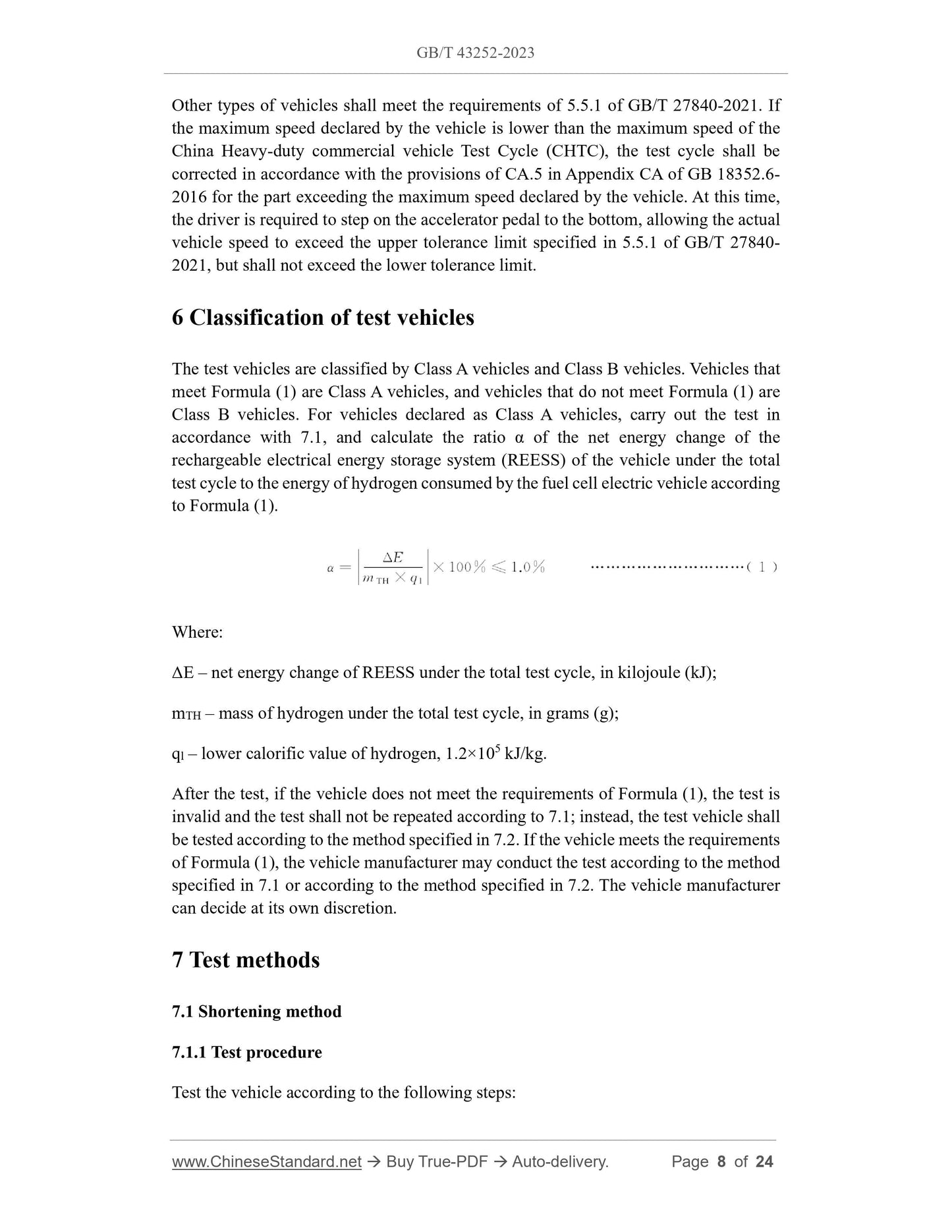
The test vehicles are classified by Class A vehicles and Class B vehicles. Vehicles that
meet Formula (1) are Class A vehicles, and vehicles that do not meet Formula (1) are
Class B vehicles. For vehicles declared as Class A vehicles, carry out the test in
accordance with 7.1, and calculate the ratio α of the net energy change of the
rechargeable electrical energy storage system (REESS) of the vehicle under the total
test cycle to the energy of hydrogen consumed by the fuel cell electric vehicle according
to Formula (1).
Where:
ΔE – net energy change of REESS under the total test cycle, in kilojoule (kJ);
mTH – mass of hydrogen under the total test cycle, in grams (g);
ql – lower calorific value of hydrogen, 1.2×10⁵ kJ/kg.
After the test, if the vehicle does not meet the requirements of Formula (1), the test is
invalid and the test shall not be repeated according to 7.1; instead, the test vehicle shall
be tested according to the method specified in 7.2. If the vehicle meets the requirements
of Formula (1), the vehicle manufacturer may conduct the test according to the method
specified in 7.1 or according to the method specified in 7.2. The vehicle manufacturer
can decide at its own discretion.
7 Test methods
7.1 Shortening method
7.1.1 Test procedure
Test the vehicle according to the following steps:
a) Adopt the method of supplying hydrogen outside the vehicle;
b) Before the test, adjust the SOC state of the vehicle REESS according to the
requirements of the vehicle manufacturer;
c) Fix the vehicle on the chassis dynamometer and set the resistance according to
the provisions of 5.4;
d) Run the vehicle for a complete cycle on the chassis dynamometer; at the end of
the cycle, turn off the vehicle and leave to stand for 15 minutes;
e) Carry out the driving range test under working conditions in accordance with
7.1.2.
7.1.2 Driving range test under working conditions
The steps for the driving range test under working conditions are as follows.
a) Carry out the driving range test under working conditions according to the
provisions in Table 2. The vehicle shall not be stopped during the test until the
end of the test.
b) Begin sampling from the start of the vehicle, with a sampling frequency of not
less than 5 Hz, until the end of the test. The collected parameters include REESS
voltage UREESS, REESS current IREESS, vehicle traveled distance DT, and
hydrogen mass mTH.
c) The measurement method of hydrogen consumption can refer to the method
specified in GB/T 35178-2017.
d) Hydrogen bottle cut-off pressure test: Before the test, the hydrogen in the
hydrogen bottle on the vehicle shall be guaranteed to be able to travel for at least
one complete cycle. Fix the vehicle on the chassis dynamometer and set the
resistance according to the provisions of 5.4. Carry out the cyclic working
condition test in accordance with the provisions of GB/T 38146.1 and GB/T
38146.2 (see Table 2 for the selection of cyclic working condition types). The
vehicle shall not be stopped during the test (except for stopping within the
working condition cycle), and at least one complete cycle shall be driven. When
the vehicle meets the requirements of 7.2.3, stop the test and measure the
internal pressure of the hydrogen bottle. Measure the internal pressure of the
hydrogen bottle according to the method specified in A.3 of Appendix A, and
record the pressure P4. This pressure value is the cut-off pressure of the hydrogen
bottle. The cut-off pressure measurement of the hydrogen bottle shall be
completed within 30 minutes.
18386.2-2022, and measure and record the energy E from the power grid; for
non-externally rechargeable fuel cell electric vehicles, proceed to step f).
f) Move the vehicle to the hydrogenation unit, add hydrogen according to the
provisions of A.2 and calculate the mass of hydrogen mTH. Keep four significant
figures after the decimal point of the calculation result (round off).
Except for step b) and step c), between any two steps, if the vehicle needs to move:
-- For Category-M1, Category-N1, as well as Category-M2 with a maximum design
total mass not exceeding 3 500 kg, it is not allowed to use the power on the
vehicle to move the vehicle to the next test location, and the regeneration
braking system shall be turned off;
-- For other types of vehicles, the use of on-board power is allowed. The vehicle is
required to travel at a speed not exceeding 30 km/h or the speed limit of the
factory area, and move between the two test locations as evenly as possible. The
shift distance of the vehicle between the two test locations each time shall not
exceed 3 km.
7.2.2 Driving range test under working conditions
The steps for the driving range test under working conditions are as follows.
a) Carry out the driving range test under working conditions according to the
provisions of Table 3; do not step the test until the range specified in 7.2.3 is
reached.
b) Unless otherwise specified, the number of stops during the working condition
test cycle shall not exceed 3 times (stops outside the operating cycle), and the
total cumulative stop time shall not exceed 15 minutes. During the stop period,
turn off the test bench fan, and do not use an external power supply to charge
the vehicle.
c) Begin sampling from the start of the vehicle, with a sampling frequency of not
less than 5 Hz, until the end of the test. The collected parameters include the fuel
cell stack voltage UFC, the fuel cell stack current IFC, the REESS voltage UREESS,
the REESS current IREESS, and the distance D traveled by the vehicle (the
measured value is rounded to an integer, and this distance is the driving range
measured by the working condition method); at the same time, record the time
used in hours (h) and minutes (min).
Note: For vehicles of which the fuel cell stack voltage UFC and fuel cell stack current
IFC cannot be measured directly, measure the voltage and current at the output
of the DC/DC converter, and then convert the power of the fuel cell stack. The
DC/DC converter conversion efficiency is 97.0%.
e) Based on T2 and P2, refer to the temperature-pressure method in Appendix A of
GB/T 35178-2017 to calculate the mass m1 of hydrogen carried by the vehicle
before the test.
A.2 Hydrogenation after vehicle testing
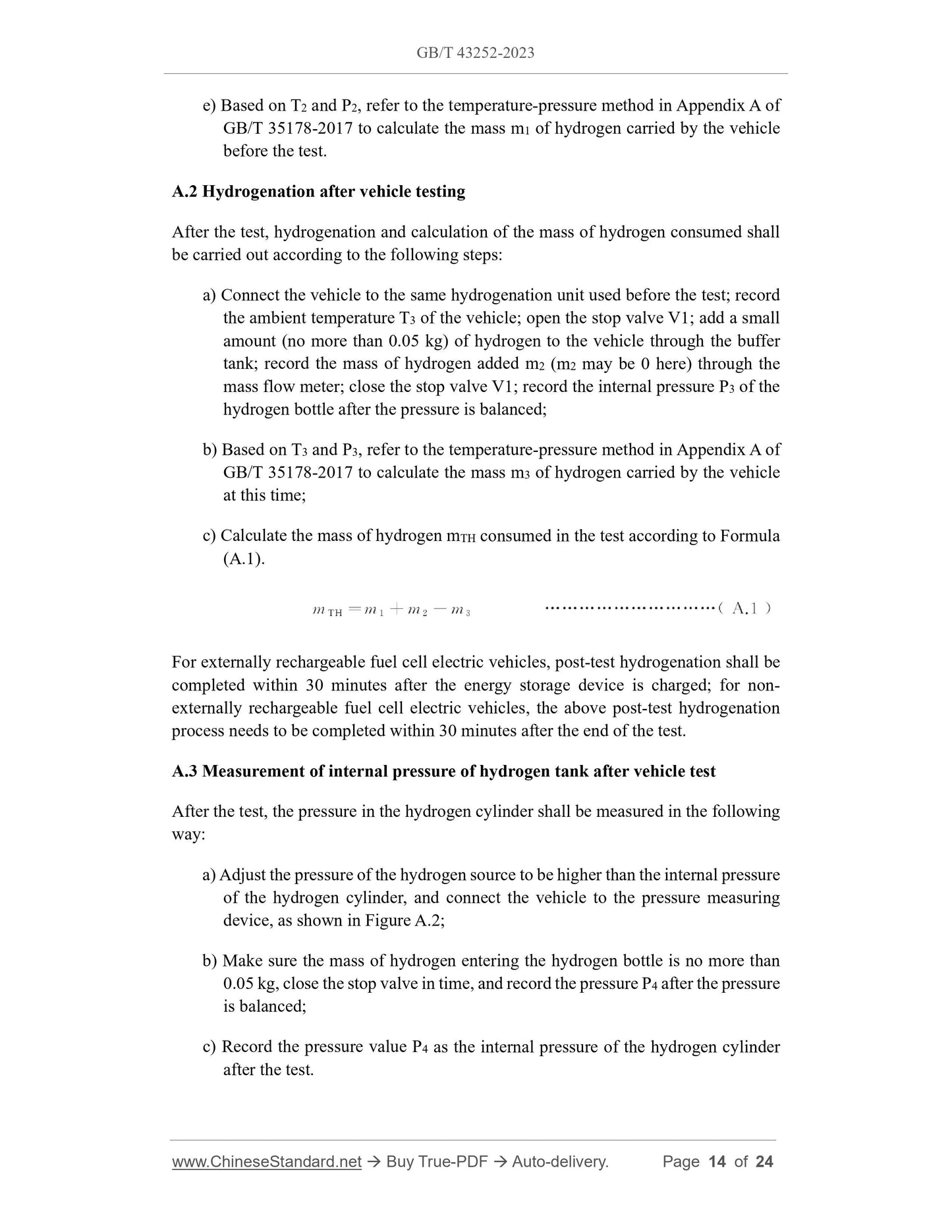
After the test, hydrogenation and calculation of the mass of hydrogen consumed shall
be carried out according to the following steps:
a) Connect the vehicle to the same hydrogenation unit used before the test; record
the ambient temperature T3 of the vehicle; open the stop valve V1; add a small
amount (no more than 0.05 kg) of hydrogen to the vehicle through the buffer
tank; record the mass of hydrogen added m2 (m2 may be 0 here) through the
mass flow meter; close the stop valve V1; record the internal pressure P3 of the
hydrogen bottle after the pressure is balanced;
b) Based on T3 and P3, refer to the temperature-pressure method in Appendix A of
GB/T 35178-2017 to calculate the mass m3 of hydrogen carried by the vehicle
at this time;
c) Calculate the mass of hydrogen mTH consumed in the test according to Formula
(A.1).
For externally rechargeable fuel cell electric vehicles, post-test hydrogenation shall be
completed within 30 minutes after the energy storage device is charged; for non-
externally rechargeable fuel cell electric vehicles, the above post-test hydrogenation
process needs to be completed within 30 minutes after the end of the test.
A.3 Measurement of internal pressure of hydrogen tank after vehicle test
After the test, the pressure in the hydrogen cylinder shall be measured in the following
way:
a) Adjust the pressure of the hydrogen source to be higher than the internal pressure
of the hydrogen cylinder, and connect the vehicle to the pressure measuring
device, as shown in Figure A.2;
b) Make sure the mass of hydrogen entering the hydrogen bottle is no more than
0.05 kg, close the stop valve in time, and record the pressure P4 after the pressure...
Share
