1
/
of
7
PayPal, credit cards. Download editable-PDF and invoice in 1 second!
HG/T 20611-2009 English PDF (HG/T20611-2009)
HG/T 20611-2009 English PDF (HG/T20611-2009)
Regular price
$75.00 USD
Regular price
Sale price
$75.00 USD
Unit price
/
per
Shipping calculated at checkout.
Couldn't load pickup availability
Delivery: 3 seconds. Download true-PDF + Invoice.
Get QUOTATION in 1-minute: Click HG/T 20611-2009
Historical versions: HG/T 20611-2009
Preview True-PDF (Reload/Scroll if blank)
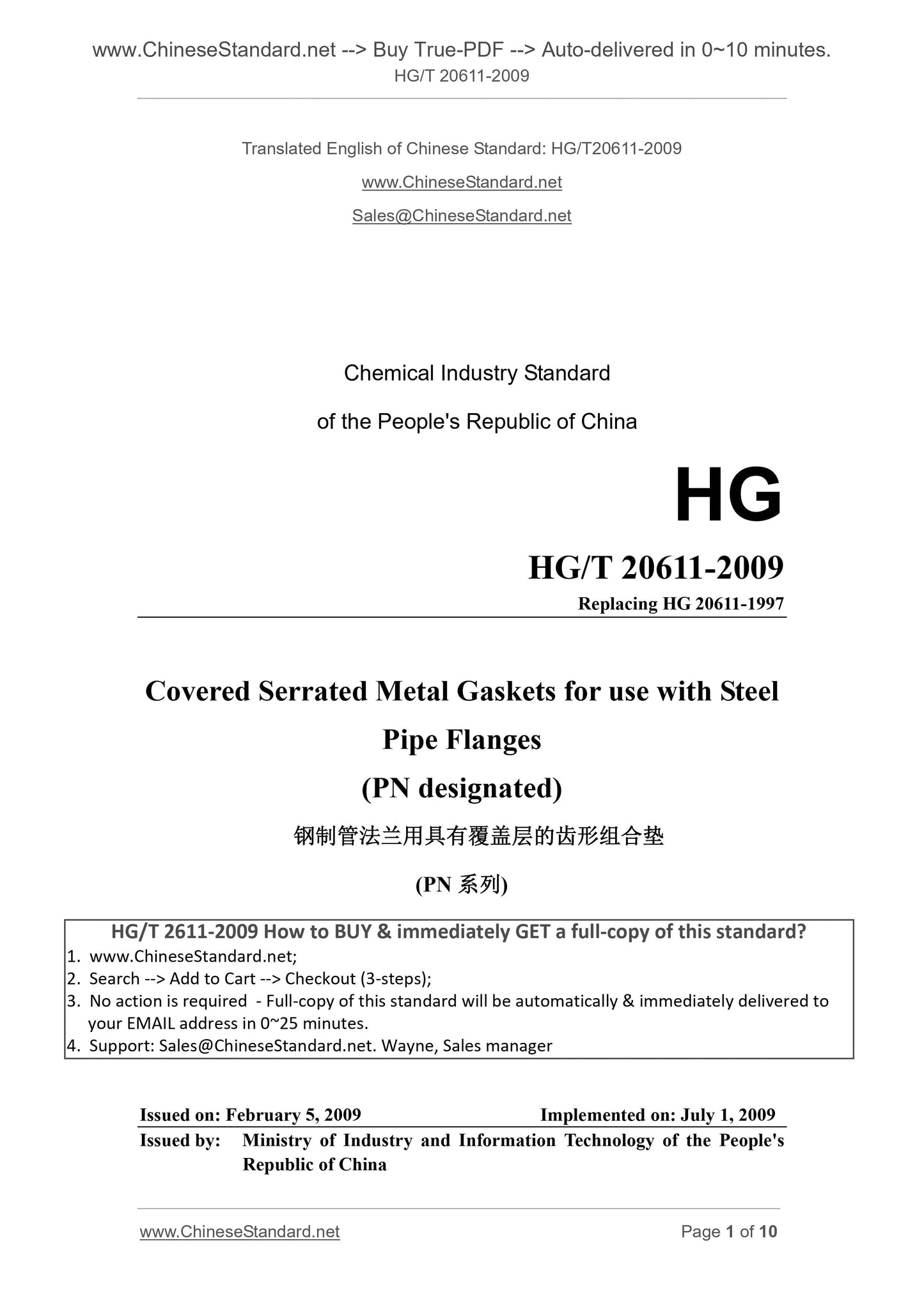
HG/T 20611-2009: Covered serrated metal gaskets for use with steel pipe flanges (PN designated)
HG/T 20611-2009
Chemical Industry Standard
of the People's Republic of China
HG
Replacing HG 20611-1997
Covered Serrated Metal Gaskets for use with Steel
Pipe Flanges
(PN designated)
(PN系列)
ISSUED ON. FEBRUARY 5, 2009
IMPLEMENTED ON. JULY 1, 2009
Issued by. Ministry of Industry and Information Technology of the People's
Republic of China
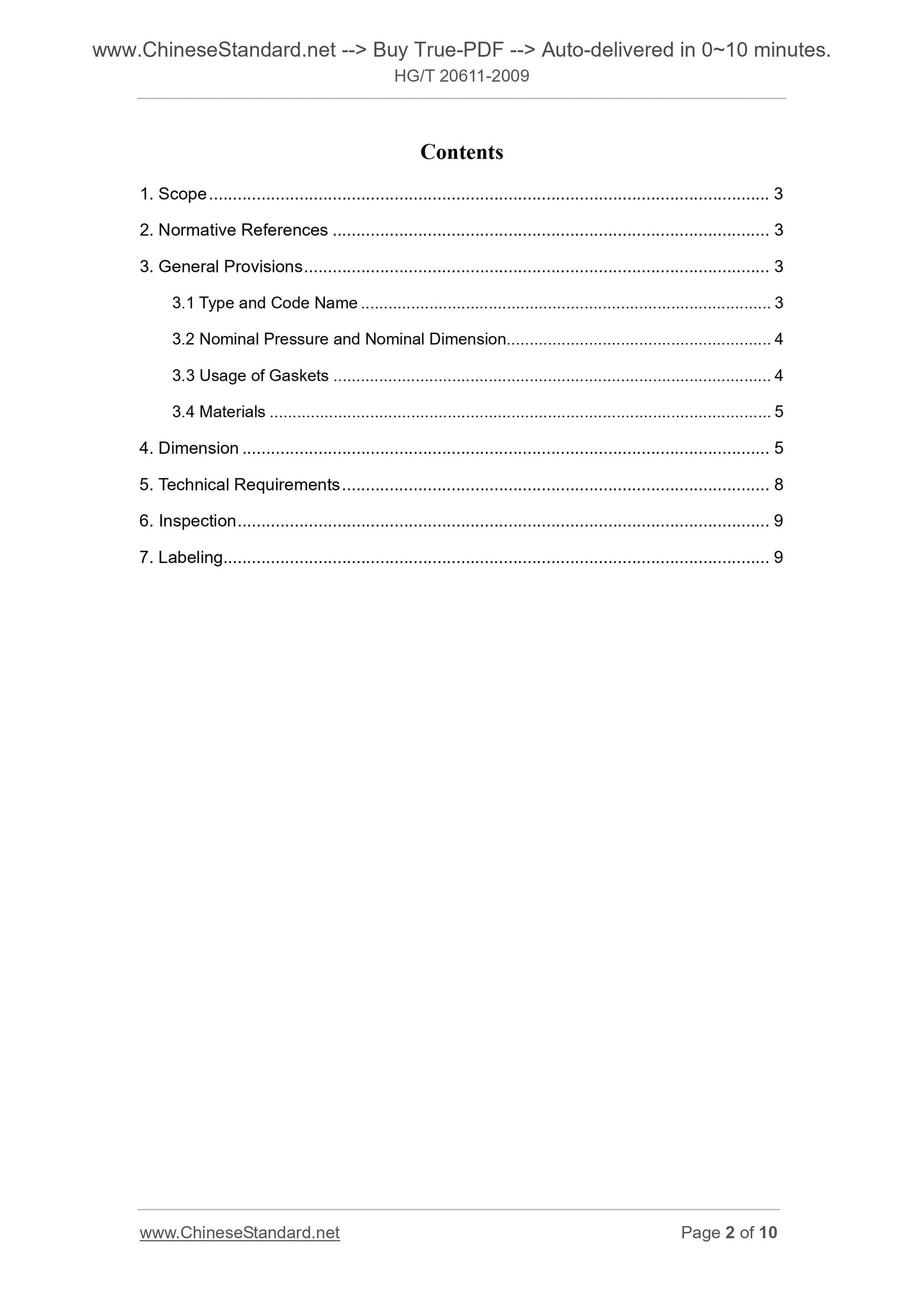
Contents
1. Scope ... 3
2. Normative References ... 3
3. General Provisions ... 3
3.1 Type and Code Name ... 3
3.2 Nominal Pressure and Nominal Dimension ... 4
3.3 Usage of Gaskets ... 4
3.4 Materials ... 5
4. Dimension ... 5
5. Technical Requirements ... 8
6. Inspection ... 9
7. Labeling... 9
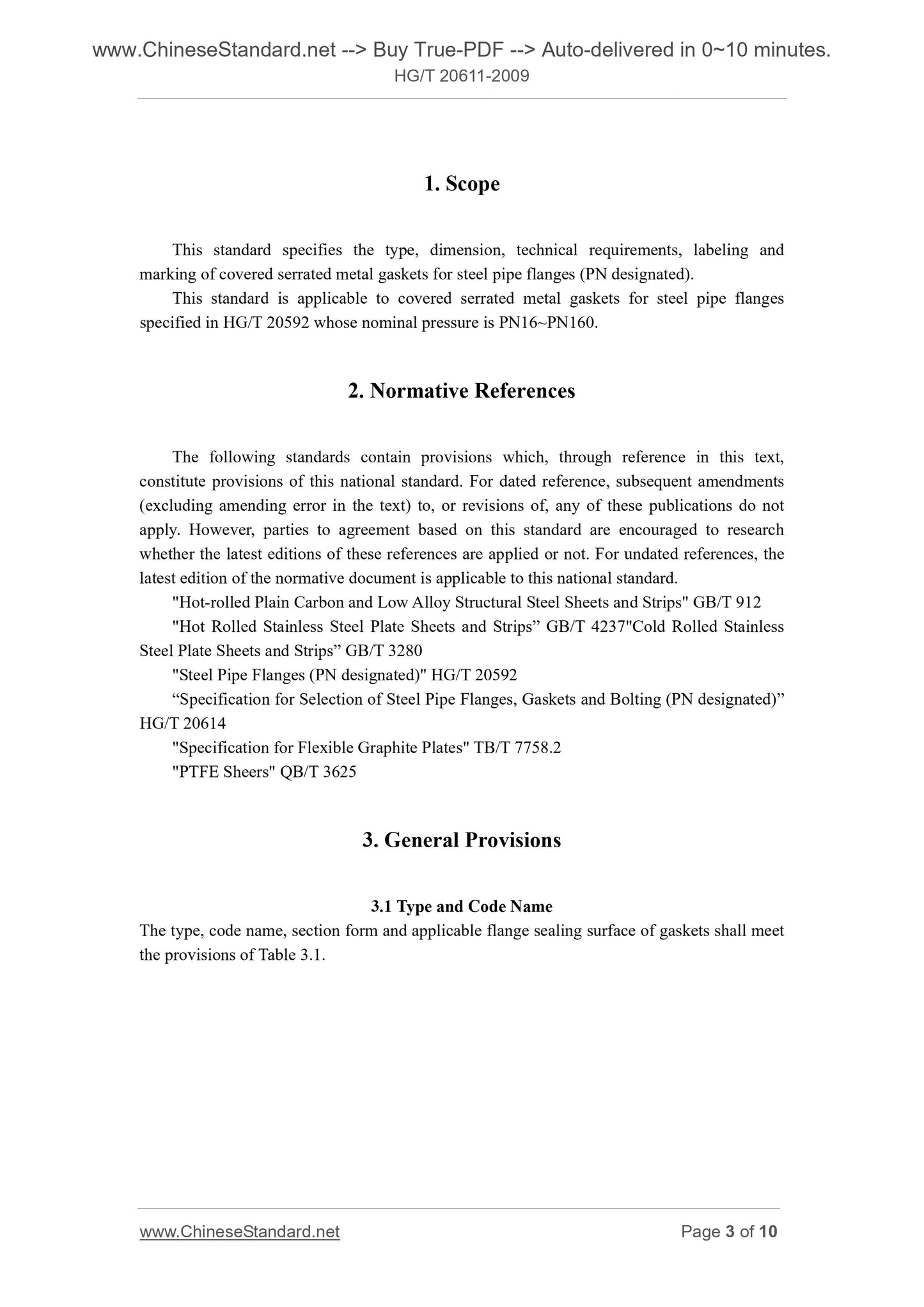
1. Scope
This standard specifies the type, dimension, technical requirements, labeling and
marking of covered serrated metal gaskets for steel pipe flanges (PN designated).
This standard is applicable to covered serrated metal gaskets for steel pipe flanges
specified in HG/T 20592 whose nominal pressure is PN16~PN160.
2. Normative References
The following standards contain provisions which, through reference in this text,
constitute provisions of this national standard. For dated reference, subsequent amendments
(excluding amending error in the text) to, or revisions of, any of these publications do not
apply. However, parties to agreement based on this standard are encouraged to research
whether the latest editions of these references are applied or not. For undated references, the
latest edition of the normative document is applicable to this national standard.
"Hot-rolled Plain Carbon and Low Alloy Structural Steel Sheets and Strips" GB/T 912
"Hot Rolled Stainless Steel Plate Sheets and Strips” GB/T 4237"Cold Rolled Stainless
Steel Plate Sheets and Strips” GB/T 3280
"Steel Pipe Flanges (PN designated)" HG/T 20592
“Specification for Selection of Steel Pipe Flanges, Gaskets and Bolting (PN designated)”
HG/T 20614
"Specification for Flexible Graphite Plates" TB/T 7758.2
"PTFE Sheers" QB/T 3625
3. General Provisions
3.1 Type and Code Name
The type, code name, section form and applicable flange sealing surface of gaskets shall meet
the provisions of Table 3.1.
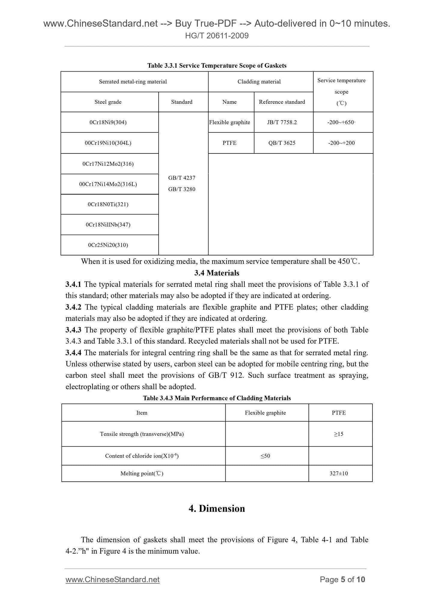
Table 3.3.1 Service Temperature Scope of Gaskets
Serrated metal-ring material Cladding material Service temperature
scope
( )℃ Steel grade Standard Name Reference standard
0Cr18Ni9(304)
GB/T 4237
GB/T 3280
Flexible graphite JB/T 7758.2 -200~+650·
00Cr19Ni10(304L) PTFE QB/T 3625 -200~+200
0Cr17Ni12Mo2(316)
00Cr17Ni14Mo2(316L)
0Cr18N0Ti(321)
0Cr18NillNb(347)
0Cr25Ni20(310)
When it is used for oxidizing media, the maximum service temperature shall be 450 . ℃
3.4 Materials
3.4.1 The typical materials for serrated metal ring shall meet the provisions of Table 3.3.1 of
this standard; other materials may also be adopted if they are indicated at ordering.
3.4.2 The typical cladding materials are flexible graphite and PTFE plates; other cladding
materials may also be adopted if they are indicated at ordering.
3.4.3 The property of flexible graphite/PTFE plates shall meet the provisions of both Table
3.4.3 and Table 3.3.1 of this standard. Recycled materials shall not be used for PTFE.
3.4.4 The materials for integral centring ring shall be the same as that for serrated metal ring.
Unless otherwise stated by users, carbon steel can be adopted for mobile centring ring, but the
carbon steel shall meet the provisions of GB/T 912. Such surface treatment as spraying,
electroplating or others shall be adopted.
Table 3.4.3 Main Performance of Cladding Materials
Item Flexible graphite PTFE
Tensile strength (transverse)(MPa) ≥15
Content of chloride ion(X10-6) ≤50
Melting point( )℃ 327±10
4. Dimension
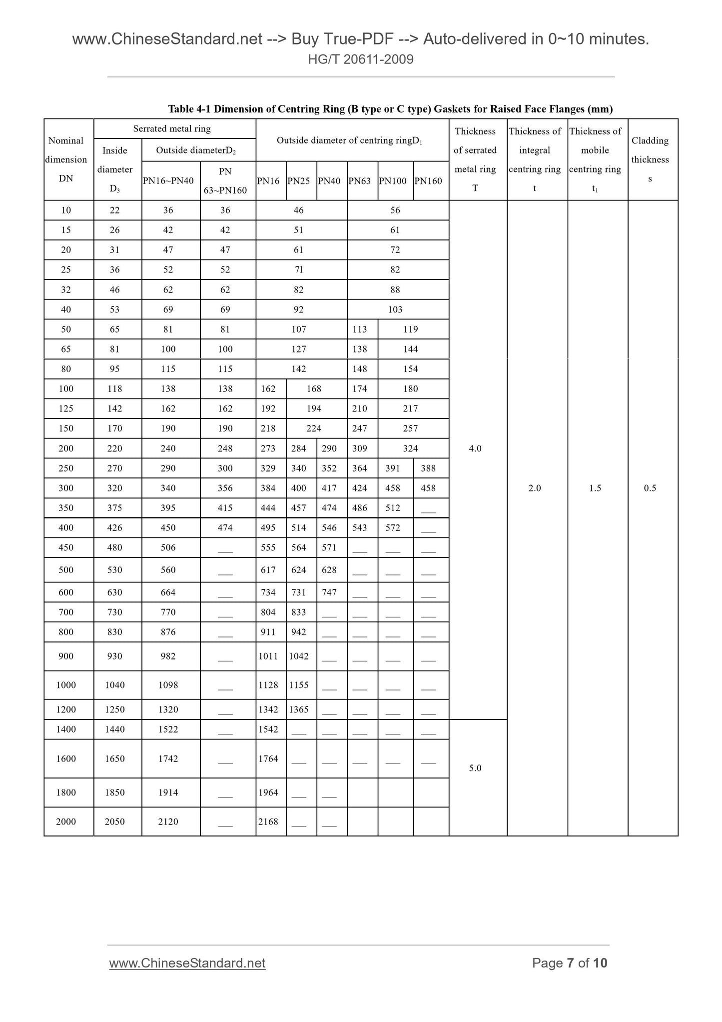
The dimension of gaskets shall meet the provisions of Figure 4, Table 4-1 and Table
4-2.”h" in Figure 4 is the minimum value.
Table 4-1 Dimension of Centring Ring (B type or C type) Gaskets for Raised Face Flanges (mm)
Nominal
dimension
DN
Serrated metal ring
Outside diameter of centring ringD1
Thickness
of serrated
metal ring
Thickness of
integral
centring ring
Thickness of
mobile
centring ring
t1
Cladding
thickness
Inside
diameter
D3
Outside diameterD2
PN16~PN40 PN 63~PN160 PN16 PN25 PN40 PN63 PN100 PN160
10 22 36 36 46 56
15 26 42 42 51 61
20 31 47 47 61 72
25 36 52 52 7l 82
32 46 62 62 82 88
40 53 69 69 92 103
50 65 81 81 107 113 119
65 81 100 100 127 138 144
80 95 115 115 142 148 154
100 118 138 138 162 168 174 180
125 142 162 162 192 194 210 217
150 170 190 190 218 224 247 257
200 220 240 248 273 284 290 309 324 4.0
250 270 290 300 329 340 352 364 391 388
300 320 340 356 384 400 417 424 458 458 2.0 1.5 0.5
350 375 395 415 444 457 474 486 512 ___
400 426 450 474 495 514 546 543 572 ___
450 480 506 ___ 555 564 571 ___ ___ ___
500 530 560 ___ 617 624 628 ___ ___ ___
600 630 664 ___ 734 731 747 ___ ___ ___
700 730 770 ___ 804 833 ___ ___ ___ ___
800 830 876 ___ 911 942 ___ ___ ___ ___
900 930 982 ___ 1011 1042 ___ ___ ___ ___
1000 1040 1098 ___ 1128 1155 ___ ___ ___ ___
1200 1250 1320 ___ 1342 1365 ___ ___ ___ ___
1400 1440 1522 ___ 1542 ___ ___ ___ ___ ___
1600 1650 1742 ___ 1764 ___ ___ ___ ___ ___ 5.0
1800 1850 1914 ___ 1964 ___ ___
2000 2050 2120 ___ 2168 ___ ___
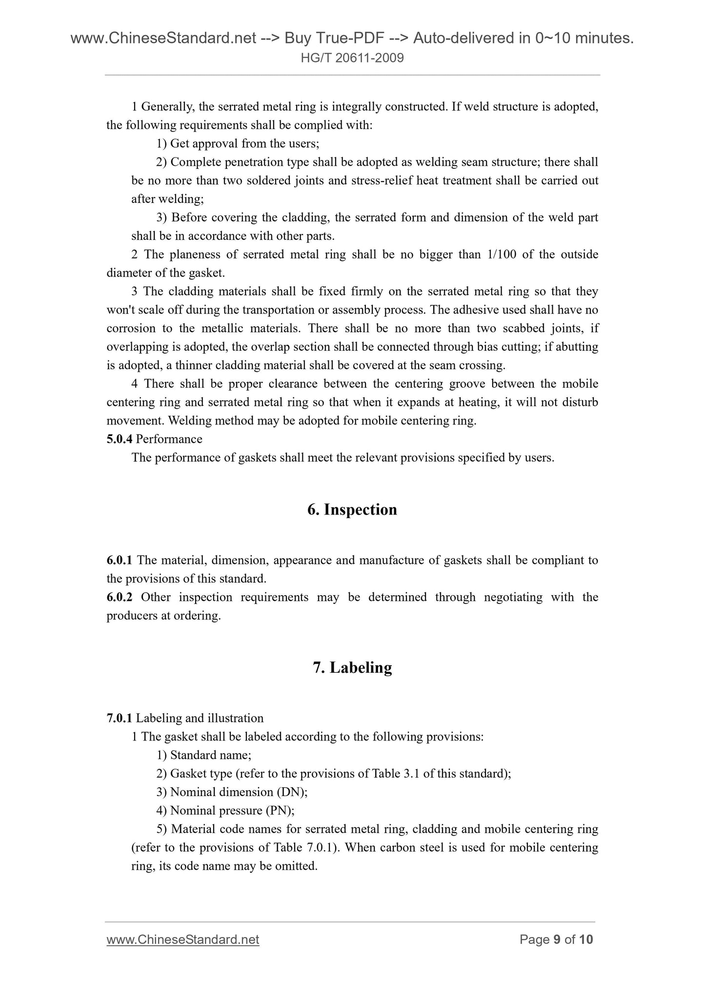
1 Generally, the serrated metal ring is integrally constructed. If weld structure is adopted,
the following requirements shall be complied with.
1) Get approval from the users;
2) Complete penetration type shall be adopted as welding seam structure; there shall
be no more than two soldered joints and stress-relief heat treatment shall be carried out
after welding;
3) Before covering the cladding, the serrated form and dimension of the weld part
shall be in accordance with other parts.
2 The planeness of serrated metal ring shall be no bigger than 1/100 of the outside
diameter of the gasket.
3 The cladding materials shall be fixed firmly on the serrated metal ring so that they
won't scale off during the transportation or assembly process. The adhesive used shall have no
corrosion to the metallic materials. There shall be no more than two scabbed joints, if
overlapping is adopted, the overlap section shall be connected through bias cutting; if abutting
is adopted, a thinner cladding material shall be covered at the seam crossing.
4 There shall be proper clearance between the centering groove between the mobile
centering ring and serrated metal ring so that when it expands at heating, it will not disturb
movement. Welding method may be adopted for mobile centering ring.
5.0.4 Performance
The performance of gaskets shall meet the relevant provisions specified by users.
6. Inspection
6.0.1 The material, dimension, appearance and manufacture of gaskets shall be compliant to
the provisions of this standard.
6.0.2 Other inspection requirements may be determined through negotiating with the
producers at ordering.
7. Labeling
7.0.1 Labeling and illustration
1 The gasket shall be labeled according to the following provisions.
1) Standard name;
2) Gasket type (refer to the provisions of Table 3.1 of this standard);
3) Nominal dimension (DN);
4) Nominal pressure (PN);
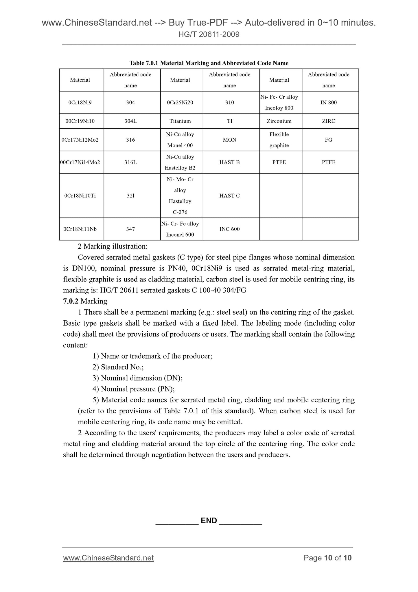
5) Material code names for serrated metal ring, cladding and mobile centering ring
(refer to the provisions of Table 7.0.1). When carbon steel...
Share
