1
/
of
5
PayPal, credit cards. Download editable-PDF and invoice in 1 second!
JB/T 5313-2001 English PDF (JB/T5313-2001)
JB/T 5313-2001 English PDF (JB/T5313-2001)
Regular price
$390.00 USD
Regular price
Sale price
$390.00 USD
Unit price
/
per
Shipping calculated at checkout.
Couldn't load pickup availability
Delivery: 3 seconds. Download true-PDF + Invoice.
Get QUOTATION in 1-minute: Click JB/T 5313-2001
Historical versions: JB/T 5313-2001
Preview True-PDF (Reload/Scroll if blank)
JB/T 5313-2001: Rolling bearing. Measuring methods for vibration(velocity)
JB/T 5313-2001
JB
MECHANICAL INDUSTRY STANDARD
OF THE PEOPLE’S REPUBLIC OF CHINA
ICS 21.100.20
J 11
Rolling Bearing - Measuring Methods for Vibration
(Velocity)
ISSUED ON: MAY 23, 2001
IMPLEMENTED ON: OCTOBER 01, 2001
Issued by: China Machinery Industry Federation
Table of Contents
Foreword ... 3
1 Scope ... 4
2 Normative References ... 4
3 Term and Definitions ... 4
4 Physical Quantity and Unit ... 5
5 Assessment of Bearing Vibration (Velocity) ... 5
6 Test Conditions ... 5
7 Test Method and Procedure ... 11
Rolling Bearing - Measuring Methods for Vibration
(Velocity)
1 Scope
This standard specifies measuring methods for vibration (velocity) of DN 3~120mm
deep groove ball bearings, angular contact ball bearing, tapered roller bearing and
cylindrical roller bearing (Types N, NU, NJ and NF).
This standard is applicable to the inspection of the vibration (velocity) of rolling
bearings above by laboratory, manufacturer and users.
2 Normative References
The following normative documents contain the provisions which, through reference in
this standard, constitute the provisions of this standard. At time of publication, the
editions indicated were valid. All the standards will be revised, all parties who reach an
agreement according to this standard are encouraged to study whether the latest editions
of the following standards are applicable.
GB/T 307.1-1994 Rolling Bearings - Radial Bearings - Tolerances
GB/T 6930-1986 Rolling bearings - Vocabulary
3 Term and Definitions
3.1 Bearing vibration
All movements with periodic variation are called bearing vibration, except some
intrinsic, function-required movements between bearing parts in the rotation.
Bearing vibration measured in this standard refers to: the radial vibration velocity of
bearing outer ring -- where the raceway center section is intersected with the cylindrical
surface (highest point) outside the outer ring, when inner ring end face of bearing abuts
against mandrel shoulder and rotates at some constant rotation speed, and while the
outer ring does not rotate but bears certain radial or axial loads.
3.2 Bearing vibration (velocity) value
Under certain rotation speed and test load, it is tested at three equidistant points at the
direction of the cylindrical surface circumference outside bearing outer ring and the
arithmetic mean of vibration speeds at the high-, medium- and low-frequency band, that
is the vibration (velocity) value of this bearing at the corresponding frequency band. If
the bearing needs to be tested on both sides, the higher value (mean value of three points)
at each frequency band is the vibration (velocity) value of the bearing at this frequency
band.
4 Physical Quantity and Unit
The physical quantity for vibration of measured bearing is the radial vibration velocity
of bearing outer ring, μm/s.
5 Assessment of Bearing Vibration (Velocity)
5.1 Frequency range
Within 50~10000Hz frequency range, the three measuring frequency bands of bearing
vibration (velocity) shall be according to those specified in Table 1.
5.2 Time averaging method
The vibration speed signal at each measuring point shall be measured for not less than
0.5s and not be read until the pointer is still. If the signal is fluctuated, the medium value
of the fluctuation range shall be taken.
6 Test Conditions
6.1 Mechanical device
6.1.1 Basic vibration
Start main drive axle (each frequency band range switch placed at minimum gear), press
transducer measuring point down so that it is at the condition identical to the test mode;
in this case, the indicated values at each frequency band shall be in accordance with
those specified in Table 2.
Figure 2 -- Radial Load Plant Diagram
The applied composite radial load is down vertically, its action line has an included
angle not greater than 2° with the vertical line of main drive axle center, the distance to
the main drive axle center line shall be less than 0.5mm.
6.1.5 Transducer holder
The transducer holder may move along axis direction and vertical direction of main
drive axle separately, and ensure that the action line of the transducer on contact load
of measured bearing outer ring has an included angle not greater than 2° with vertical
line of main drive axle center, the distance off the axial line shall be less than 0.2mm.
6.2 Transducer
What is induced by the transducer is the rate of change in radial vibration displacement
of bearing outer ring.
6.2.1 Within 50~10000Hz frequency range, the transducer and the measured bearing
outer ring shall be free from separation, and the contact load of transducer for the
measured bearing outer ring must be less than 0.7N.
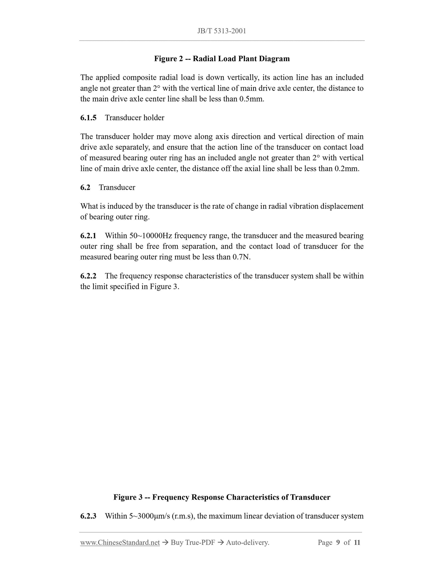
6.2.2 The frequency response characteristics of the transducer system shall be within
the limit specified in Figure 3.
Figure 3 -- Frequency Response Characteristics of Transducer
6.2.3 Within 5~3000μm/s (r.m.s), the maximum linear deviation of transducer system
Get QUOTATION in 1-minute: Click JB/T 5313-2001
Historical versions: JB/T 5313-2001
Preview True-PDF (Reload/Scroll if blank)
JB/T 5313-2001: Rolling bearing. Measuring methods for vibration(velocity)
JB/T 5313-2001
JB
MECHANICAL INDUSTRY STANDARD
OF THE PEOPLE’S REPUBLIC OF CHINA
ICS 21.100.20
J 11
Rolling Bearing - Measuring Methods for Vibration
(Velocity)
ISSUED ON: MAY 23, 2001
IMPLEMENTED ON: OCTOBER 01, 2001
Issued by: China Machinery Industry Federation
Table of Contents
Foreword ... 3
1 Scope ... 4
2 Normative References ... 4
3 Term and Definitions ... 4
4 Physical Quantity and Unit ... 5
5 Assessment of Bearing Vibration (Velocity) ... 5
6 Test Conditions ... 5
7 Test Method and Procedure ... 11
Rolling Bearing - Measuring Methods for Vibration
(Velocity)
1 Scope
This standard specifies measuring methods for vibration (velocity) of DN 3~120mm
deep groove ball bearings, angular contact ball bearing, tapered roller bearing and
cylindrical roller bearing (Types N, NU, NJ and NF).
This standard is applicable to the inspection of the vibration (velocity) of rolling
bearings above by laboratory, manufacturer and users.
2 Normative References
The following normative documents contain the provisions which, through reference in
this standard, constitute the provisions of this standard. At time of publication, the
editions indicated were valid. All the standards will be revised, all parties who reach an
agreement according to this standard are encouraged to study whether the latest editions
of the following standards are applicable.
GB/T 307.1-1994 Rolling Bearings - Radial Bearings - Tolerances
GB/T 6930-1986 Rolling bearings - Vocabulary
3 Term and Definitions
3.1 Bearing vibration
All movements with periodic variation are called bearing vibration, except some
intrinsic, function-required movements between bearing parts in the rotation.
Bearing vibration measured in this standard refers to: the radial vibration velocity of
bearing outer ring -- where the raceway center section is intersected with the cylindrical
surface (highest point) outside the outer ring, when inner ring end face of bearing abuts
against mandrel shoulder and rotates at some constant rotation speed, and while the
outer ring does not rotate but bears certain radial or axial loads.
3.2 Bearing vibration (velocity) value
Under certain rotation speed and test load, it is tested at three equidistant points at the
direction of the cylindrical surface circumference outside bearing outer ring and the
arithmetic mean of vibration speeds at the high-, medium- and low-frequency band, that
is the vibration (velocity) value of this bearing at the corresponding frequency band. If
the bearing needs to be tested on both sides, the higher value (mean value of three points)
at each frequency band is the vibration (velocity) value of the bearing at this frequency
band.
4 Physical Quantity and Unit
The physical quantity for vibration of measured bearing is the radial vibration velocity
of bearing outer ring, μm/s.
5 Assessment of Bearing Vibration (Velocity)
5.1 Frequency range
Within 50~10000Hz frequency range, the three measuring frequency bands of bearing
vibration (velocity) shall be according to those specified in Table 1.
5.2 Time averaging method
The vibration speed signal at each measuring point shall be measured for not less than
0.5s and not be read until the pointer is still. If the signal is fluctuated, the medium value
of the fluctuation range shall be taken.
6 Test Conditions
6.1 Mechanical device
6.1.1 Basic vibration
Start main drive axle (each frequency band range switch placed at minimum gear), press
transducer measuring point down so that it is at the condition identical to the test mode;
in this case, the indicated values at each frequency band shall be in accordance with
those specified in Table 2.
Figure 2 -- Radial Load Plant Diagram
The applied composite radial load is down vertically, its action line has an included
angle not greater than 2° with the vertical line of main drive axle center, the distance to
the main drive axle center line shall be less than 0.5mm.
6.1.5 Transducer holder
The transducer holder may move along axis direction and vertical direction of main
drive axle separately, and ensure that the action line of the transducer on contact load
of measured bearing outer ring has an included angle not greater than 2° with vertical
line of main drive axle center, the distance off the axial line shall be less than 0.2mm.
6.2 Transducer
What is induced by the transducer is the rate of change in radial vibration displacement
of bearing outer ring.
6.2.1 Within 50~10000Hz frequency range, the transducer and the measured bearing
outer ring shall be free from separation, and the contact load of transducer for the
measured bearing outer ring must be less than 0.7N.
6.2.2 The frequency response characteristics of the transducer system shall be within
the limit specified in Figure 3.
Figure 3 -- Frequency Response Characteristics of Transducer
6.2.3 Within 5~3000μm/s (r.m.s), the maximum linear deviation of transducer system
Share