1
/
of
7
www.ChineseStandard.us -- Field Test Asia Pte. Ltd.
JB/T 7403-1994 English PDF (JB/T7403-1994)
JB/T 7403-1994 English PDF (JB/T7403-1994)
Regular price
$470.00
Regular price
Sale price
$470.00
Unit price
/
per
Shipping calculated at checkout.
Couldn't load pickup availability
JB/T 7403-1994: Illuminometer
Delivery: 9 seconds. Download (& Email) true-PDF + Invoice.
Get Quotation: Click JB/T 7403-1994 (Self-service in 1-minute)
Historical versions (Master-website): JB/T 7403-1994
Preview True-PDF (Reload/Scroll-down if blank)
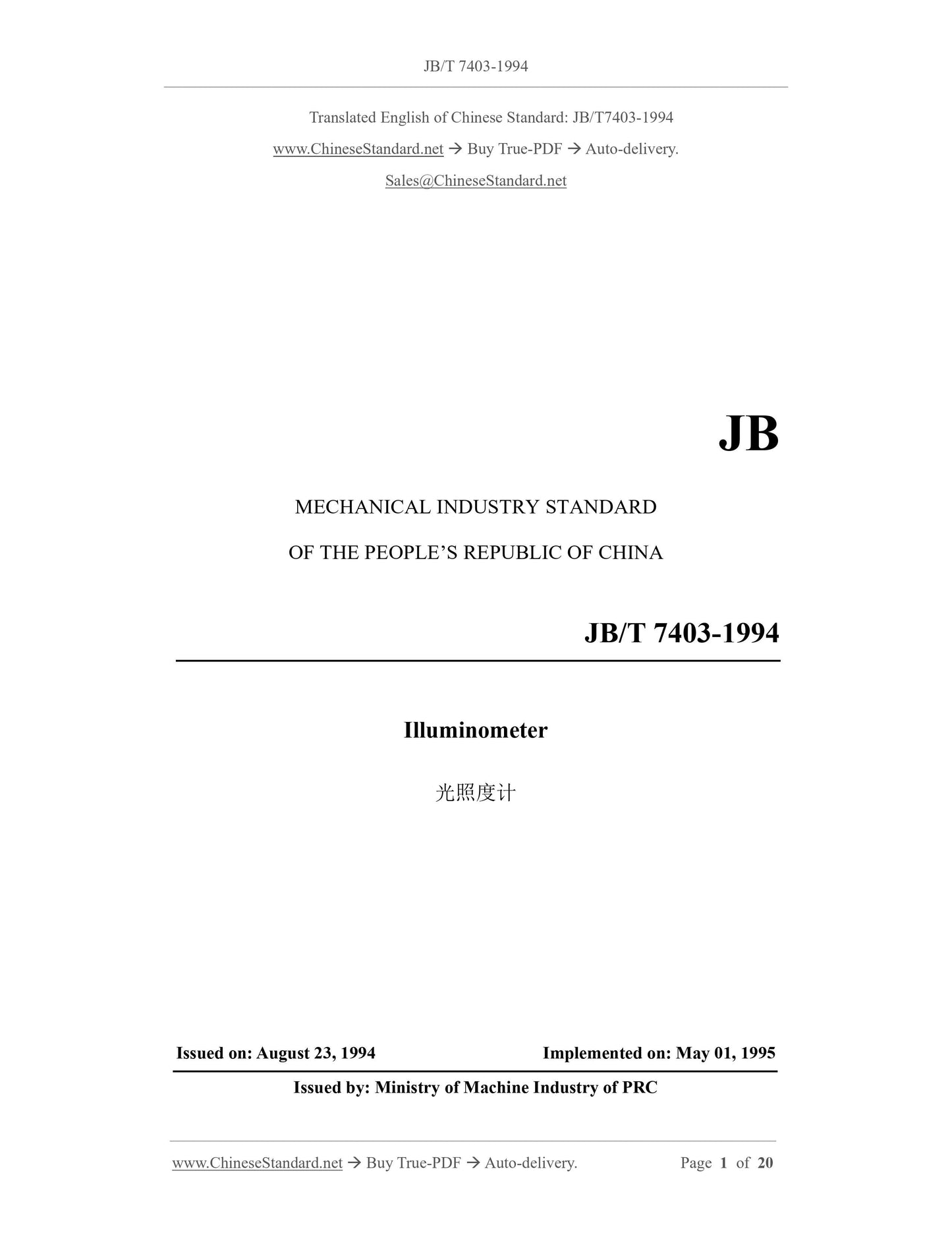
JB/T 7403-1994
JB
MECHANICAL INDUSTRY STANDARD
OF THE PEOPLE’S REPUBLIC OF CHINA
Illuminometer
光照度计
ISSUED ON: AUGUST 23, 1994
IMPLEMENTED ON: MAY 01, 1995
Issued by: Ministry of Machine Industry of PRC
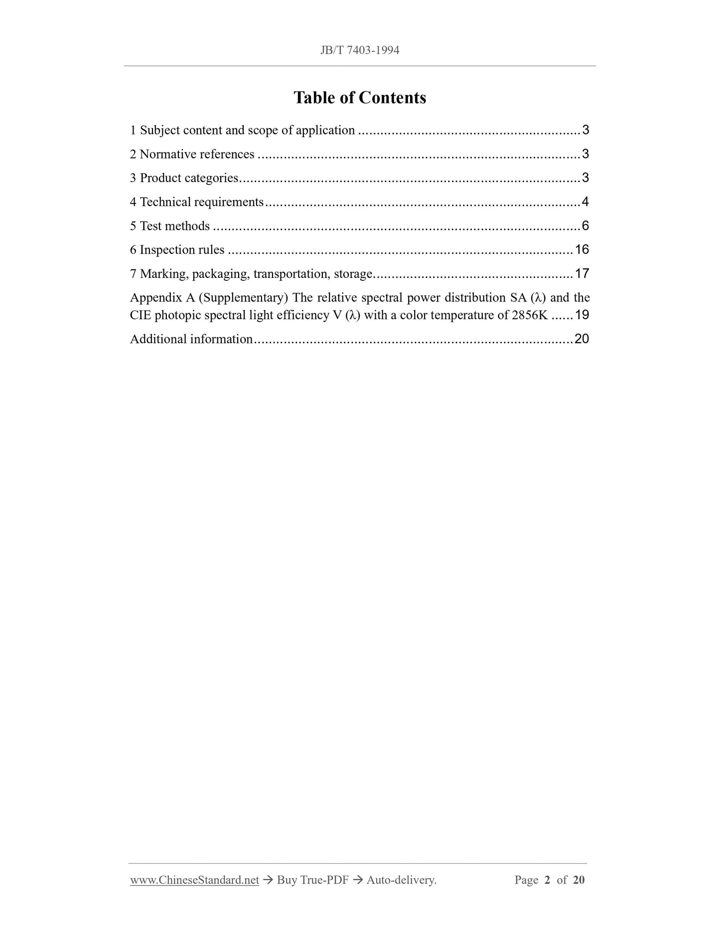
Table of Contents
1 Subject content and scope of application ... 3
2 Normative references ... 3
3 Product categories ... 3
4 Technical requirements ... 4
5 Test methods ... 6
6 Inspection rules ... 16
7 Marking, packaging, transportation, storage ... 17
Appendix A (Supplementary) The relative spectral power distribution SA (λ) and the
CIE photopic spectral light efficiency V (λ) with a color temperature of 2856K ... 19
Additional information ... 20
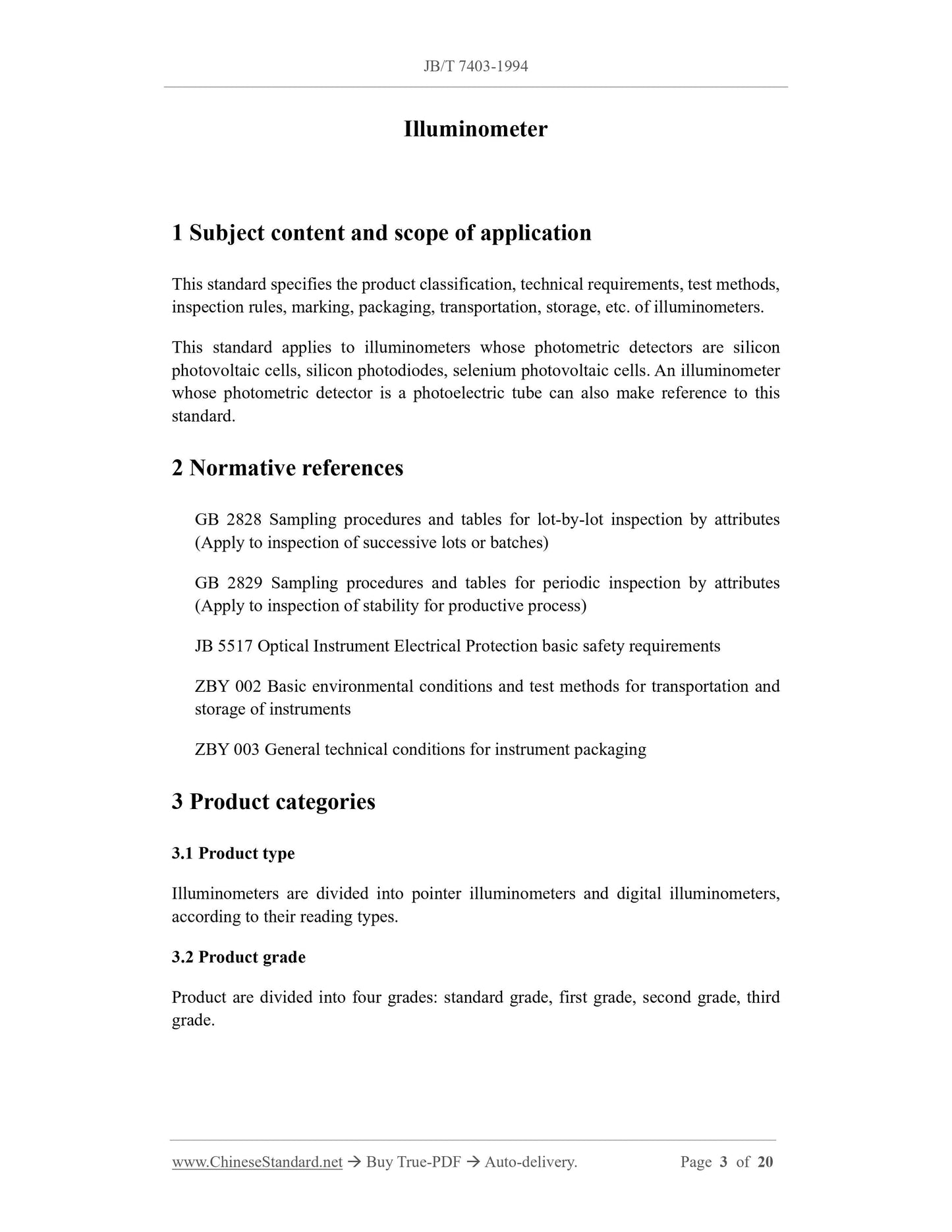
Illuminometer
1 Subject content and scope of application
This standard specifies the product classification, technical requirements, test methods,
inspection rules, marking, packaging, transportation, storage, etc. of illuminometers.
This standard applies to illuminometers whose photometric detectors are silicon
photovoltaic cells, silicon photodiodes, selenium photovoltaic cells. An illuminometer
whose photometric detector is a photoelectric tube can also make reference to this
standard.
2 Normative references
GB 2828 Sampling procedures and tables for lot-by-lot inspection by attributes
(Apply to inspection of successive lots or batches)
GB 2829 Sampling procedures and tables for periodic inspection by attributes
(Apply to inspection of stability for productive process)
JB 5517 Optical Instrument Electrical Protection basic safety requirements
ZBY 002 Basic environmental conditions and test methods for transportation and
storage of instruments
ZBY 003 General technical conditions for instrument packaging
3 Product categories
3.1 Product type
Illuminometers are divided into pointer illuminometers and digital illuminometers,
according to their reading types.
3.2 Product grade
Product are divided into four grades: standard grade, first grade, second grade, third
grade.
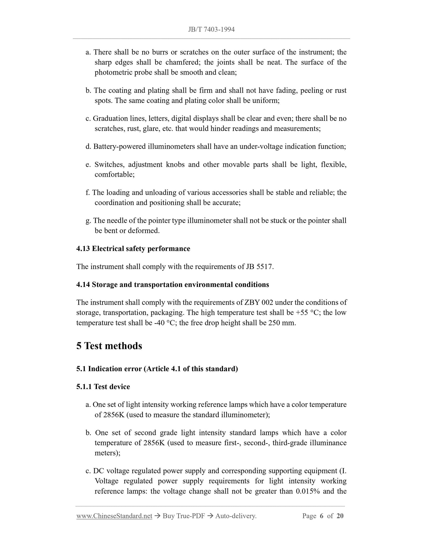
a. There shall be no burrs or scratches on the outer surface of the instrument; the
sharp edges shall be chamfered; the joints shall be neat. The surface of the
photometric probe shall be smooth and clean;
b. The coating and plating shall be firm and shall not have fading, peeling or rust
spots. The same coating and plating color shall be uniform;
c. Graduation lines, letters, digital displays shall be clear and even; there shall be no
scratches, rust, glare, etc. that would hinder readings and measurements;
d. Battery-powered illuminometers shall have an under-voltage indication function;
e. Switches, adjustment knobs and other movable parts shall be light, flexible,
comfortable;
f. The loading and unloading of various accessories shall be stable and reliable; the
coordination and positioning shall be accurate;
g. The needle of the pointer type illuminometer shall not be stuck or the pointer shall
be bent or deformed.
4.13 Electrical safety performance
The instrument shall comply with the requirements of JB 5517.
4.14 Storage and transportation environmental conditions
The instrument shall comply with the requirements of ZBY 002 under the conditions of
storage, transportation, packaging. The high temperature test shall be +55 °C; the low
temperature test shall be -40 °C; the free drop height shall be 250 mm.
5 Test methods
5.1 Indication error (Article 4.1 of this standard)
5.1.1 Test device
a. One set of light intensity working reference lamps which have a color temperature
of 2856K (used to measure the standard illuminometer);
b. One set of second grade light intensity standard lamps which have a color
temperature of 2856K (used to measure first-, second-, third-grade illuminance
meters);
c. DC voltage regulated power supply and corresponding supporting equipment (I.
Voltage regulated power supply requirements for light intensity working
reference lamps: the voltage change shall not be greater than 0.015% and the
Where:
S(λ) - Relative spectral power distribution of black light lamp (or deuterium lamp);
τUV(λ) - Spectral transmittance of ZWB1 UV-transmitting glass sheet;
Y(UV) - The indicated value of the illuminometer with ZWB1 ultraviolet transparent
glass sheet, lx;
Y - The indicated value of the illuminometer without ZWB1 ultraviolet transparent
glass sheet, lx;
Uo - The integrated transmittance of the combination of ZWB1 ultraviolet
transparent glass sheet and black light lamp (or deuterium lamp);
f4 - UV response error.
5.6 Fatigue error (Article 4.6 of this standard)
5.6.1 Test device
Same as Article 5.1.1 a ~ d of this standard.
5.6.2 Test procedure
Adjust the distance between the light source and the photometric probe on the
photometric guide rail, so that the photometric probe can receive nearly 1000 lx
illumination. Read out the indicated value of the illuminometer, when irradiating for 10
seconds. Then read out the indicated value of the illuminometer, when continuing
irradiating for 30 minutes. Calculate the fatigue error according to formula (11):
Where:
Y(30 min) - The indicated value of the illuminometer when irradiated for 30 minutes,
lx;
Y(10 s) - The indicated value of the illuminometer when irradiated for 10 seconds,
lx;
f5 - Fatigue error.
5.7 Nonlinear error (Article 4.7 of this standard)
5.7.1 Test device
Same as Article 5.1.1 a ~ d of this standard.
5.7.2 Test procedure
Adjust the distance between the light-emitting surface of the light source and the test
surface of the photometric probe on the photometric guide rail. Find the standard
illuminance value Xmax, which is corresponding to the full range of the illuminometer.
Meanwhile read out the indicated value Ymax of the illuminometer. Then move the
photometric probe (or light source) to a position which is 1/10 of the full range.
Calculate the standard illuminance value X; read out the indicated value Y of the
illuminometer. At least the nonlinear error of each gear below the l000 lx range shall be
measured. Calculate the nonlinear error of each gear according to formula (12):
Where:
Y - The indicated value of the illuminometer at 1/10 full range, lx;
Ymax - The indicated value of the illuminometer at full range, lx;
X - The standard illuminance value at 1/10 full range, lx;
Xmax - The standard illuminance value at full range, lx;
f6 - Linearity error.
5.8 Gear shift error (Article 4.8 of this standard)
5.8.1 Test device
Same as Article 5.1.1 a ~ d of this standard.
5.8.2 Test procedure
Adjust the distance from the light-emitting surface of the light source to the test surface
of the photometric probe on the photometric guide rail. Find the standard illuminance
value X (A) of the illuminometer, which is equivalent to that the illuminometer is at 90%
of full range when it is at low range (gear A); meanwhile read out the indication value
Y (A) of the illuminometer. Then move the photometric probe (or light source) on the
photometric guide rail, to the position where the standard illuminance value is K times
higher than XA. Switch the illuminometer to gear B. Read out the indicated value Y(B).
Calculate the gear shift error according to formula (13):
Where:
Where:
ΔY - The maximum deviation of the illuminometer from the zero position, lx;
Y - The full-range value of the illuminometer, lx;
f9 - Zero drift error.
5.11 Temperature coefficient (Article 4.11 of this standard)
5.11.1 Test device
a. Same as Article 5.1.1 a ~ c of this standard;
b. Temperature controller.
5.11.2 Test procedure
Place the illuminometer inside the temperature controller, with the indicator facing out
the window. Place the standard lamp outside the temperature controller, to illuminate
the photometric probe. Control the current of the standard lamp to remain constant and
keep the relative position of the illuminometer and the light source constant. Control
the temperature respectively at 5 °C, 20 °C, 40 °C, respectively. After maintaining
temperature at each gear for one hour, read the indicated value of the illuminometer.
Then calculate according to formula (16).
Where:
T1 - High temperature, which takes 40 °C;
T2 - Low temperature, which takes 5 °C;
To - Normal temperature, which takes 20 °C;
Y(T1) - The indicated value of the illuminometer at 40 °C, lx;
Y(T2) - The indicated value of the illuminometer at 5 °C, lx;
Y(To) - The indicated value of the illuminometer at 20 °C, lx;
α - Temperature coefficient.
5.12 Instrument appearance and sensory requirements (Article 4.12 of this
JB/T 7403-1994
JB
MECHANICAL INDUSTRY STANDARD
OF THE PEOPLE’S REPUBLIC OF CHINA
Illuminometer
光照度计
ISSUED ON: AUGUST 23, 1994
IMPLEMENTED ON: MAY 01, 1995
Issued by: Ministry of Machine Industry of PRC
Table of Contents
1 Subject content and scope of application ... 3
2 Normative references ... 3
3 Product categories ... 3
4 Technical requirements ... 4
5 Test methods ... 6
6 Inspection rules ... 16
7 Marking, packaging, transportation, storage ... 17
Appendix A (Supplementary) The relative spectral power distribution SA (λ) and the
CIE photopic spectral light efficiency V (λ) with a color temperature of 2856K ... 19
Additional information ... 20
Illuminometer
1 Subject content and scope of application
This standard specifies the product classification, technical requirements, test methods,
inspection rules, marking, packaging, transportation, storage, etc. of illuminometers.
This standard applies to illuminometers whose photometric detectors are silicon
photovoltaic cells, silicon photodiodes, selenium photovoltaic cells. An illuminometer
whose photometric detector is a photoelectric tube can also make reference to this
standard.
2 Normative references
GB 2828 Sampling procedures and tables for lot-by-lot inspection by attributes
(Apply to inspection of successive lots or batches)
GB 2829 Sampling procedures and tables for periodic inspection by attributes
(Apply to inspection of stability for productive process)
JB 5517 Optical Instrument Electrical Protection basic safety requirements
ZBY 002 Basic environmental conditions and test methods for transportation and
storage of instruments
ZBY 003 General technical conditions for instrument packaging
3 Product categories
3.1 Product type
Illuminometers are divided into pointer illuminometers and digital illuminometers,
according to their reading types.
3.2 Product grade
Product are divided into four grades: standard grade, first grade, second grade, third
grade.
a. There shall be no burrs or scratches on the outer surface of the instrument; the
sharp edges shall be chamfered; the joints shall be neat. The surface of the
photometric probe shall be smooth and clean;
b. The coating and plating shall be firm and shall not have fading, peeling or rust
spots. The same coating and plating color shall be uniform;
c. Graduation lines, letters, digital displays shall be clear and even; there shall be no
scratches, rust, glare, etc. that would hinder readings and measurements;
d. Battery-powered illuminometers shall have an under-voltage indication function;
e. Switches, adjustment knobs and other movable parts shall be light, flexible,
comfortable;
f. The loading and unloading of various accessories shall be stable and reliable; the
coordination and positioning shall be accurate;
g. The needle of the pointer type illuminometer shall not be stuck or the pointer shall
be bent or deformed.
4.13 Electrical safety performance
The instrument shall comply with the requirements of JB 5517.
4.14 Storage and transportation environmental conditions
The instrument shall comply with the requirements of ZBY 002 under the conditions of
storage, transportation, packaging. The high temperature test shall be +55 °C; the low
temperature test shall be -40 °C; the free drop height shall be 250 mm.
5 Test methods
5.1 Indication error (Article 4.1 of this standard)
5.1.1 Test device
a. One set of light intensity working reference lamps which have a color temperature
of 2856K (used to measure the standard illuminometer);
b. One set of second grade light intensity standard lamps which have a color
temperature of 2856K (used to measure first-, second-, third-grade illuminance
meters);
c. DC voltage regulated power supply and corresponding supporting equipment (I.
Voltage regulated power supply requirements for light intensity working
reference lamps: the voltage change shall not be greater than 0.015% and the
Where:
S(λ) - Relative spectral power distribution of black light lamp (or deuterium lamp);
τUV(λ) - Spectral transmittance of ZWB1 UV-transmitting glass sheet;
Y(UV) - The indicated value of the illuminometer with ZWB1 ultraviolet transparent
glass sheet, lx;
Y - The indicated value of the illuminometer without ZWB1 ultraviolet transparent
glass sheet, lx;
Uo - The integrated transmittance of the combination of ZWB1 ultraviolet
transparent glass sheet and black light lamp (or deuterium lamp);
f4 - UV response error.
5.6 Fatigue error (Article 4.6 of this standard)
5.6.1 Test device
Same as Article 5.1.1 a ~ d of this standard.
5.6.2 Test procedure
Adjust the distance between the light source and the photometric probe on the
photometric guide rail, so that the photometric probe can receive nearly 1000 lx
illumination. Read out the indicated value of the illuminometer, when irradiating for 10
seconds. Then read out the indicated value of the illuminometer, when continuing
irradiating for 30 minutes. Calculate the fatigue error according to formula (11):
Where:
Y(30 min) - The indicated value of the illuminometer when irradiated for 30 minutes,
lx;
Y(10 s) - The indicated value of the illuminometer when irradiated for 10 seconds,
lx;
f5 - Fatigue error.
5.7 Nonlinear error (Article 4.7 of this standard)
5.7.1 Test device
Same as Article 5.1.1 a ~ d of this standard.
5.7.2 Test procedure
Adj...
Share
