1
/
of
8
PayPal, credit cards. Download editable-PDF and invoice in 1 second!
JB/T 9101-1999 English PDF (JBT9101-1999)
JB/T 9101-1999 English PDF (JBT9101-1999)
Regular price
$70.00 USD
Regular price
Sale price
$70.00 USD
Unit price
/
per
Shipping calculated at checkout.
Couldn't load pickup availability
Delivery: 3 seconds. Download true-PDF + Invoice.
Get QUOTATION in 1-minute: Click JB/T 9101-1999
Historical versions: JB/T 9101-1999
Preview True-PDF (Reload/Scroll if blank)
JB/T 9101-1999: Fan rotor balance
JB/T 9101-1999
JB
ICS 21. 120. 40
J 72
INDUSTRY STANDARD
OF THE PEOPLE’S REPUBLIC OF CHINA
Replacing ZB J72 042-90
Fan Rotor Balance
ISSUED ON . JULY 12, 1999
IMPLEMENTED ON. JANUARY 1, 2000
Issued by. State Bureau of Machine Industry
Table of Contents
Foreword ... 3
1 Scope... 4
2 Normative references ... 4
3 Terms and symbols ... 4
4 Rotor type ... 4
5 Rotor balancing method ... 4
6 Precision of balance equipment and process equipment ... 8
7 Calibration method and requirement ... 8
8 Expression method of balance quality grades ... 9
9 Determination of allowable imbalance amount ... 10
10 Inspection and verification of balance quality ... 12
11 Note of balance requirements in design diagram ... 16
Appendix A ... 17
Foreword
This standard references to and adopts ISO 1940-1.1986 "Mechanical Vibration - Balance
Quality Requirements for Rigid Rotor - Part 1. Determination of the Allowable Residual
Unbalance".
This standard is the revision of ZB J72 042-90 "Fan Rotor Balance". It only makes some
editorial changes to the previous standard.
This standard replaces ZB J72 042-90 from the implementation date.
Appendix A is informative.
This standard was proposed by and shall be under the jurisdiction of National Fan
Standardization Technical Committee.
Responsible drafting organization of this standard. Shenyang Fan Factory Co., Ltd.
Chief drafting staffs of this standard. Lin Xuemin, Chen Liangming, and Jiang Jilin.
Fan Rotor Balance
1 Scope
This standard specifies the balance method, grade of balance quality, precision requirements of
the balancing equipment, calibration method, and verification of the fan rotor.
This standard is applicable to the balance of the rotor or impeller of the centrifugal fan and axial
fan.
2 Normative references
The following standards contain provisions which, through reference in this text, constitute
provisions of this standard. At the time of publication, the editions indicated were valid. All
standards are subject to revision. The parties who enter into agreement based on this standard
are encouraged to investigate the possibility of applying the most recent editions of the
standards indicated below.
GB/T 1184-1996 "No Marking Tolerance Value of Shape and Position Tolerance"
GB/T 4201-1984 "Method of Verification for Universal Horizontal Balancing Machines"
GB/T 6444-1995 "Mechanical Vibration - Balancing Vocabulary"
3 Terms and symbols
The relevant terms and symbols which are involved in this standard shall meet the requirements
of GB/T 6444.
4 Rotor type
According to the structure, fan rotors are classified into 8 types, see Figure 1.
5 Rotor balancing method
Generally, fan rotor belongs to rigid rotor. Its balance methods are classified into single-plane
(static) balancing and double-plane (dynamic) balancing.
5.1 Single-plane (Static) Balancing
5.1.1 Single-plane (static) balancing is a kind of balance method that based on the unbalanced
force of the rotator which is approximately located in the plane where the mass center of the
rotator is located at. It is the method to use a calibration plane to perform the balancing, through
the swing in the gravitational field.
5.1.2 If the single-plane (static) balancing condition is adopted, the following requirements
shall be met.
a) If the maximum working speed n is lower than 1500 r/min, and the RATIO of the width
1) This machine number does not belong to the R40 series. According the operating requirements, it shall be kept temporarily.
6 Precision of balance equipment and process equipment
6.1 Select corresponding balance equipment according to the mass of the balance work piece
and its balance quality grade.
6.2 The balance equipment must be measured regularly according to the requirements of GB/T
4201. And its precision shall be equal to or higher than the requirement of the balance quality.
6.3 The balance shaft itself shall be equipped with adequate rigidity. Its mass shall be minimized.
And it shall be double-plane (dynamic) balanced. Its balance quality grade is 2.5mm/s.
6.4 The coordination between the balance shaft and impeller must not have gaps. The coaxial
tolerance BETWEEN the balance supporting surface or axial diameter on the driving end of the
balance shaft AND the work piece coordination parts shall not be more than 0.02mm. The
balance supporting surface shall be hardening. Its hardness is not less than 40 HRC. The
roughness Ra of the supporting surface is not more than 1.60μm. The cylindrical tolerance shall
not be less than the grade 6 tolerance specified in GB/T 1184.
6.5 If the rotor is single-bond structure, half-bond (half mass of the bond. That is, remain the
bond’s length and width unchanged, the height is halved) shall be equipped in the corresponding
bond groove for the balance compensation.
7 Calibration method and requirement
7.1 The material quality of the welded-structure impeller calibration mass (counter weight)
shall be identical to that of the welded parental material. Its thickness shall not be more than
the thickness of the welded parental material. Use the same method of welding impeller to full-
weld it on the lateral surface of the impeller disk (cover). The surrounding of the calibration
mass (counter weight) shall be chamfering. The contour shall be clean and neat. The welding
seams must not have crack. The quantity and position of the calibration mass (counter weight)
are same as the requirements of 7.5.
7.2 The calibration mass (counter weight) of riveted structure impeller is typically fixed to the
lateral surface of the impeller disc (cover) by adopting riveting method. The rivet’s quality,
diameter and quantity (quantity shall not be less than 2, and it shall have a certain interval
distance) shall be determined by strength calculation. The quantity, shape and position of the
calibration mass (counter weight) are same as the requirements of 7.1 and 7.5.
7.3 When the calibration mass (counter weight) of the cast structural impeller and band pulley
id fixed onto the steel plate with screws, the screw’s quality, diameter and quantity (quantity
shall not be less than 2, and it shall have a certain interval distance) shall be determined by
strength calculation. Anti-loosing measures must be taken after fastening the screws. The
quantity, shape and position of the calibration mass (counter weight) are same as the
requirements of 7.1 and 7.5.
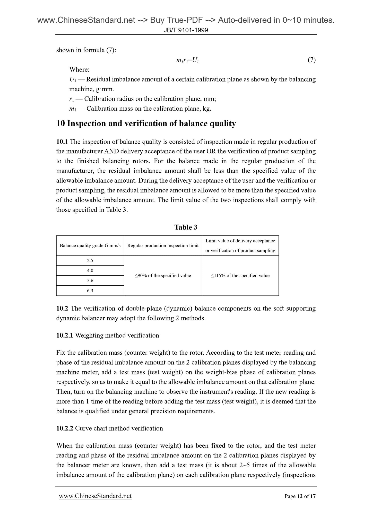
shown in formula (7).
miri=Ui (7)
Where.
Ui — Residual imbalance amount of a certain calibration plane as shown by the balancing
machine, g·mm.
ri — Calibration radius on the calibration plane, mm;
m i — Calibration mass on the calibration plane, kg.
10 Inspection and verification of balance quality
10.1 The inspection of balance quality is consisted of inspection made in regular production of
the manufacturer AND delivery acceptance of the user OR the verification of product sampling
to the finished balancing rotors. For the balance made in the regular production of the
manufacturer, the residual imbalance amount shall be less than the specified value of the
allowable imbalance amount. During the delivery acceptance of the user and the verification or
product sampling, the residual imbalance amount is allowed to be more than the specified value
of the allowable imbalance amount. The limit value of the two inspections shall comply with
those specified in Table 3.
Table 3
Balance quality grade G mm/s Re...
Get QUOTATION in 1-minute: Click JB/T 9101-1999
Historical versions: JB/T 9101-1999
Preview True-PDF (Reload/Scroll if blank)
JB/T 9101-1999: Fan rotor balance
JB/T 9101-1999
JB
ICS 21. 120. 40
J 72
INDUSTRY STANDARD
OF THE PEOPLE’S REPUBLIC OF CHINA
Replacing ZB J72 042-90
Fan Rotor Balance
ISSUED ON . JULY 12, 1999
IMPLEMENTED ON. JANUARY 1, 2000
Issued by. State Bureau of Machine Industry
Table of Contents
Foreword ... 3
1 Scope... 4
2 Normative references ... 4
3 Terms and symbols ... 4
4 Rotor type ... 4
5 Rotor balancing method ... 4
6 Precision of balance equipment and process equipment ... 8
7 Calibration method and requirement ... 8
8 Expression method of balance quality grades ... 9
9 Determination of allowable imbalance amount ... 10
10 Inspection and verification of balance quality ... 12
11 Note of balance requirements in design diagram ... 16
Appendix A ... 17
Foreword
This standard references to and adopts ISO 1940-1.1986 "Mechanical Vibration - Balance
Quality Requirements for Rigid Rotor - Part 1. Determination of the Allowable Residual
Unbalance".
This standard is the revision of ZB J72 042-90 "Fan Rotor Balance". It only makes some
editorial changes to the previous standard.
This standard replaces ZB J72 042-90 from the implementation date.
Appendix A is informative.
This standard was proposed by and shall be under the jurisdiction of National Fan
Standardization Technical Committee.
Responsible drafting organization of this standard. Shenyang Fan Factory Co., Ltd.
Chief drafting staffs of this standard. Lin Xuemin, Chen Liangming, and Jiang Jilin.
Fan Rotor Balance
1 Scope
This standard specifies the balance method, grade of balance quality, precision requirements of
the balancing equipment, calibration method, and verification of the fan rotor.
This standard is applicable to the balance of the rotor or impeller of the centrifugal fan and axial
fan.
2 Normative references
The following standards contain provisions which, through reference in this text, constitute
provisions of this standard. At the time of publication, the editions indicated were valid. All
standards are subject to revision. The parties who enter into agreement based on this standard
are encouraged to investigate the possibility of applying the most recent editions of the
standards indicated below.
GB/T 1184-1996 "No Marking Tolerance Value of Shape and Position Tolerance"
GB/T 4201-1984 "Method of Verification for Universal Horizontal Balancing Machines"
GB/T 6444-1995 "Mechanical Vibration - Balancing Vocabulary"
3 Terms and symbols
The relevant terms and symbols which are involved in this standard shall meet the requirements
of GB/T 6444.
4 Rotor type
According to the structure, fan rotors are classified into 8 types, see Figure 1.
5 Rotor balancing method
Generally, fan rotor belongs to rigid rotor. Its balance methods are classified into single-plane
(static) balancing and double-plane (dynamic) balancing.
5.1 Single-plane (Static) Balancing
5.1.1 Single-plane (static) balancing is a kind of balance method that based on the unbalanced
force of the rotator which is approximately located in the plane where the mass center of the
rotator is located at. It is the method to use a calibration plane to perform the balancing, through
the swing in the gravitational field.
5.1.2 If the single-plane (static) balancing condition is adopted, the following requirements
shall be met.
a) If the maximum working speed n is lower than 1500 r/min, and the RATIO of the width
1) This machine number does not belong to the R40 series. According the operating requirements, it shall be kept temporarily.
6 Precision of balance equipment and process equipment
6.1 Select corresponding balance equipment according to the mass of the balance work piece
and its balance quality grade.
6.2 The balance equipment must be measured regularly according to the requirements of GB/T
4201. And its precision shall be equal to or higher than the requirement of the balance quality.
6.3 The balance shaft itself shall be equipped with adequate rigidity. Its mass shall be minimized.
And it shall be double-plane (dynamic) balanced. Its balance quality grade is 2.5mm/s.
6.4 The coordination between the balance shaft and impeller must not have gaps. The coaxial
tolerance BETWEEN the balance supporting surface or axial diameter on the driving end of the
balance shaft AND the work piece coordination parts shall not be more than 0.02mm. The
balance supporting surface shall be hardening. Its hardness is not less than 40 HRC. The
roughness Ra of the supporting surface is not more than 1.60μm. The cylindrical tolerance shall
not be less than the grade 6 tolerance specified in GB/T 1184.
6.5 If the rotor is single-bond structure, half-bond (half mass of the bond. That is, remain the
bond’s length and width unchanged, the height is halved) shall be equipped in the corresponding
bond groove for the balance compensation.
7 Calibration method and requirement
7.1 The material quality of the welded-structure impeller calibration mass (counter weight)
shall be identical to that of the welded parental material. Its thickness shall not be more than
the thickness of the welded parental material. Use the same method of welding impeller to full-
weld it on the lateral surface of the impeller disk (cover). The surrounding of the calibration
mass (counter weight) shall be chamfering. The contour shall be clean and neat. The welding
seams must not have crack. The quantity and position of the calibration mass (counter weight)
are same as the requirements of 7.5.
7.2 The calibration mass (counter weight) of riveted structure impeller is typically fixed to the
lateral surface of the impeller disc (cover) by adopting riveting method. The rivet’s quality,
diameter and quantity (quantity shall not be less than 2, and it shall have a certain interval
distance) shall be determined by strength calculation. The quantity, shape and position of the
calibration mass (counter weight) are same as the requirements of 7.1 and 7.5.
7.3 When the calibration mass (counter weight) of the cast structural impeller and band pulley
id fixed onto the steel plate with screws, the screw’s quality, diameter and quantity (quantity
shall not be less than 2, and it shall have a certain interval distance) shall be determined by
strength calculation. Anti-loosing measures must be taken after fastening the screws. The
quantity, shape and position of the calibration mass (counter weight) are same as the
requirements of 7.1 and 7.5.
shown in formula (7).
miri=Ui (7)
Where.
Ui — Residual imbalance amount of a certain calibration plane as shown by the balancing
machine, g·mm.
ri — Calibration radius on the calibration plane, mm;
m i — Calibration mass on the calibration plane, kg.
10 Inspection and verification of balance quality
10.1 The inspection of balance quality is consisted of inspection made in regular production of
the manufacturer AND delivery acceptance of the user OR the verification of product sampling
to the finished balancing rotors. For the balance made in the regular production of the
manufacturer, the residual imbalance amount shall be less than the specified value of the
allowable imbalance amount. During the delivery acceptance of the user and the verification or
product sampling, the residual imbalance amount is allowed to be more than the specified value
of the allowable imbalance amount. The limit value of the two inspections shall comply with
those specified in Table 3.
Table 3
Balance quality grade G mm/s Re...
Share