
1
/
of
6
www.ChineseStandard.us -- Field Test Asia Pte. Ltd.
JB/T 9752.3-2014 English PDF (JB/T9752.3-2014)
JB/T 9752.3-2014 English PDF (JB/T9752.3-2014)
Regular price
$220.00
Regular price
Sale price
$220.00
Unit price
/
per
Shipping calculated at checkout.
Couldn't load pickup availability
JB/T 9752.3-2014: Turbochargers - Part 3: Balance quality requirements and check methods of rotors
Delivery: 9 seconds. Download (& Email) true-PDF + Invoice.
Get Quotation: Click JB/T 9752.3-2014 (Self-service in 1-minute)
Historical versions (Master-website): JB/T 9752.3-2014
Preview True-PDF (Reload/Scroll-down if blank)
JB/T 9752.3-2014
MECHANICAL INDUSTRY STANDARD
OF THE PEOPLE’S REPUBLIC OF CHINA
ICS 27.020
J 91
Filing No.: 45824-2014
Replacing JB/T 9752.3-2004
Turbochargers - Part 3: Balance quality requirements and
check methods of rotors
ISSUED ON: MAY 06, 2014
IMPLEMENTED ON: OCTOBER 01, 2014
Issued by: Ministry of Industry and Information Technology of PRC
Table of Contents
Foreword ... 3
1 Scope ... 5
2 Normative references ... 5
3 Terms and definitions... 5
4 Overview of balance technology ... 7
4.1 Static unbalance ... 7
4.2 Couple unbalance ... 8
4.3 Dynamic unbalance ... 9
4.4 Unbalanced eccentric speed ... 10
4.5 Balance quality grade ... 10
5 Balance quality grade of rigid rotor ... 11
6 Grade of balance quality of flexible rotor and balance quality of core rotor assembly
... 11
7 Limits of balance deviation ... 13
8 Assignment of the allowable unbalance on the rotor correction plane ... 13
8.1 Single-sided balance ... 13
8.2 Double-sided balance ... 13
8.3 Determination of allowable residual unbalance ... 14
8.4 Rotor's balancing procedure ... 15
9 Balance inspection method of rotor ... 16
9.1 Calibration rotor ... 16
9.2 Calibration of balancing instrument's accuracy ... 16
9.3 Inspection of rotor's balance quality ... 18
Appendix A (Informative) Marking method of rotor's balance quality grade of
supercharger on drawing ... 19
Turbochargers - Part 3: Balance quality requirements and
check methods of rotors
1 Scope
This Part of JB/T 9752 specifies the rotor balance quality grade, the calculation and
verification method of the unbalance distribution on the two correction planes, the
balance limit of the core rotor assembly, the marking method on the drawing, of the
turbocharger (hereinafter referred to as the supercharger).
This Part describes the dynamic balancing of single-piece and core rotor assembly for
various types of supercharger rotors.
2 Normative references
The following documents are essential to the application of this document. For the dated
documents, only the versions with the dates indicated are applicable to this document;
for the undated documents, only the latest version (including all the amendments) is
applicable to this standard.
GB/T 4201 Description verification and evaluation of balancing machines
GB/T 7184 Small and medium power diesel engines - Measurement and evaluation
of vibration
GB/T 9239.1-2006 Mechanical vibration - Balance quality requirements for rotors
in a constant (rigid) state - Part 1: Specification and verification of balance
tolerances
JIS B 0905-1992 Rotating machines - Balance quality requirements of rigid rotors
3 Terms and definitions
The terms and definitions, as defined in GB/T 9239.1-2006, as well as the following
terms and definitions, apply to this document.
3.1
Balancing
Check and, if necessary, adjust the rotor mass distribution, to ensure that the residual
unbalance or journal vibration and/or the force acting on the bearing is within
specified limits, at the corresponding operating speed frequency.
3.2
Unbalance
The state of the rotor, when the vibration force or motion, which is caused by the
centrifugal force due to the rotation of the rotor, acts on the bearing.
3.3
Residual unbalance
The residual unbalance on the rotor, after balancing.
3.4
Couple unbalance
A moment unbalance, which is formed by a pair of unbalance vectors of equal
magnitude and opposite phase angles, in two spaced radial planes.
3.5
Dynamic unbalance
The state of any position of the central primary inertial axis, as relative to the axis.
3.6
Balance quality
A quantity, which is used to express the degree of balance of a rigid rotor. Its value
is the product of the rotor centroid offset multiplied by the rotor speed.
3.7
Rigid rotor
A rotor, whose working speed is lower than the first-order critical speed of the rotor
shaft.
3.8
Flexible rotor
A rotor, whose working speed is higher than the first-order critical speed of the rotor
of the pressure roller is still > 0.015 mm, after 360° rotation, the parts on the shaft shall
be replaced, to repeat the above balancing steps.
8.4.3 Balancing of core rotor assembly
Install the combined and dynamically balanced rotor into the intermediate shell. Align
the assembly marks. Tighten the end nut, to form the core rotor assembly. Then carry
out the dynamic balance of the core rotor combination. At any rotational speed, its
vibration acceleration g or vibration velocity V shall not exceed the specified value,
which is specified in Figure 5. If it exceeds, it can be corrected, by removing the weight
from the edge of the end nut, in the angular direction indicated by the balancing machine.
9 Balance inspection method of rotor
9.1 Calibration rotor
9.1.1 Make a rotor, which has the same mass and consistent support position as the
supercharger's rotor, as well as good rigidity; OR select a rotor in the product as the
calibration rotor. Put the calibration rotor on the balancing machine, on the production
line or a balancing machine, which has a higher precision, for calibration. The residual
unbalance of the calibration rotor shall reach the minimum value (close to zero), which
can be reflected by the balancing instrument. Verified calibration rotors shall be
properly stored, to prevent corrosion and deformation. For single-piece and small batch
of products, it is allowed to not keep the calibration rotor.
9.1.2 Calibration rotor shall be calibrated, at the rotating speed of the balancing machine,
which has a higher sensitivity.
9.1.3 The support position and direction of rotation, during calibrating by the calibration
rotor, shall be consistent with the working state of the product rotor.
9.1.4 Calibration rotor shall be inspected regularly; the validity period is one year.
9.2 Calibration of balancing instrument's accuracy
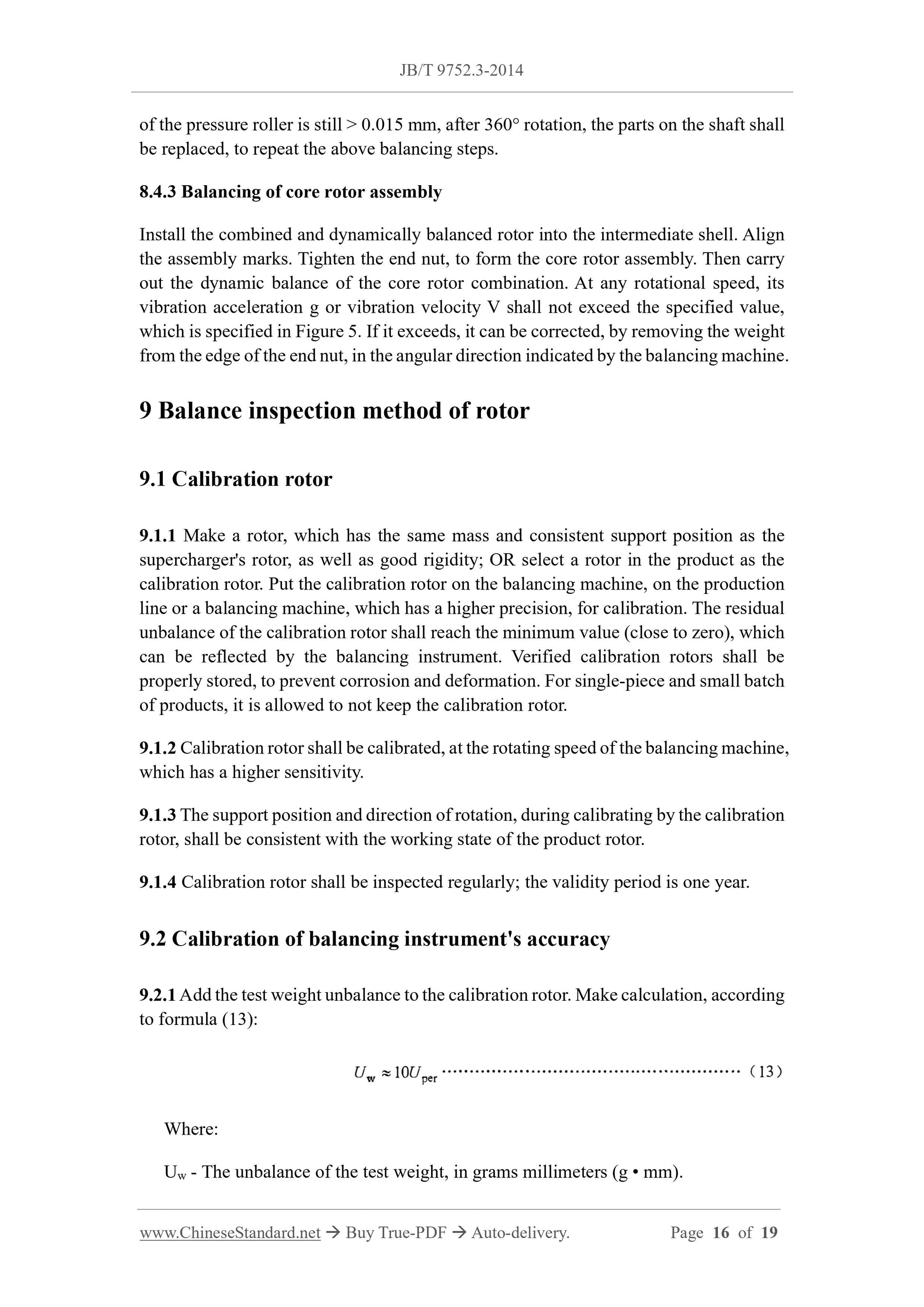
9.2.1 Add the test weight unbalance to the calibration rotor. Make calculation, according
to formula (13):
Where:
Uw - The unbalance of the test weight, in grams millimeters (g • mm).
PB - The scale value of the balancing instrument, in grams millimeter per grid.
9.3 Inspection of rotor's balance quality
9.3.1 The rotor can be divided into two types: integral assembly balance and single-
piece balance, according to the design requirements. For the rotor parts, which are
subject to integral assembly balancing, if there is no fixed position, it shall identify the
assembly mark.
9.3.2 Adjust the supporting frame of the balancing instrument, so that the supporting
position of the rotor, when it is balanced, is consistent with the actual position; the
balancing speed and direction of rotation shall be the same as the rotation speed and
direction of rotation, when the rotor is calibrated.
9.3.3 When the unbalance of the rotor is so large, that the normal work cannot be
performed, the balance speed can be reduced OR the primary balance can be carried
out by means of static balance.
9.3.4 According to the position, which is specified in the design drawing, remove the
unbalanced part, by the weight removal methods, such as grinding, milling or drilling.
9.3.5 For the rotor, which is assembled after single-piece dynamic balance, when the
dynamic balance is re-calibrated, if the indicated value of the balancing instrument
exceeds the specified range of the drawing or single-piece balancing, some parts on the
rotor (such as thrust plate, shaft seal, nut, etc.) are allowed to be replaced, OR use the
part transposition method, to carry out calibration. It may also remove the weight of the
rotor again, to meet the requirements of the design drawings.
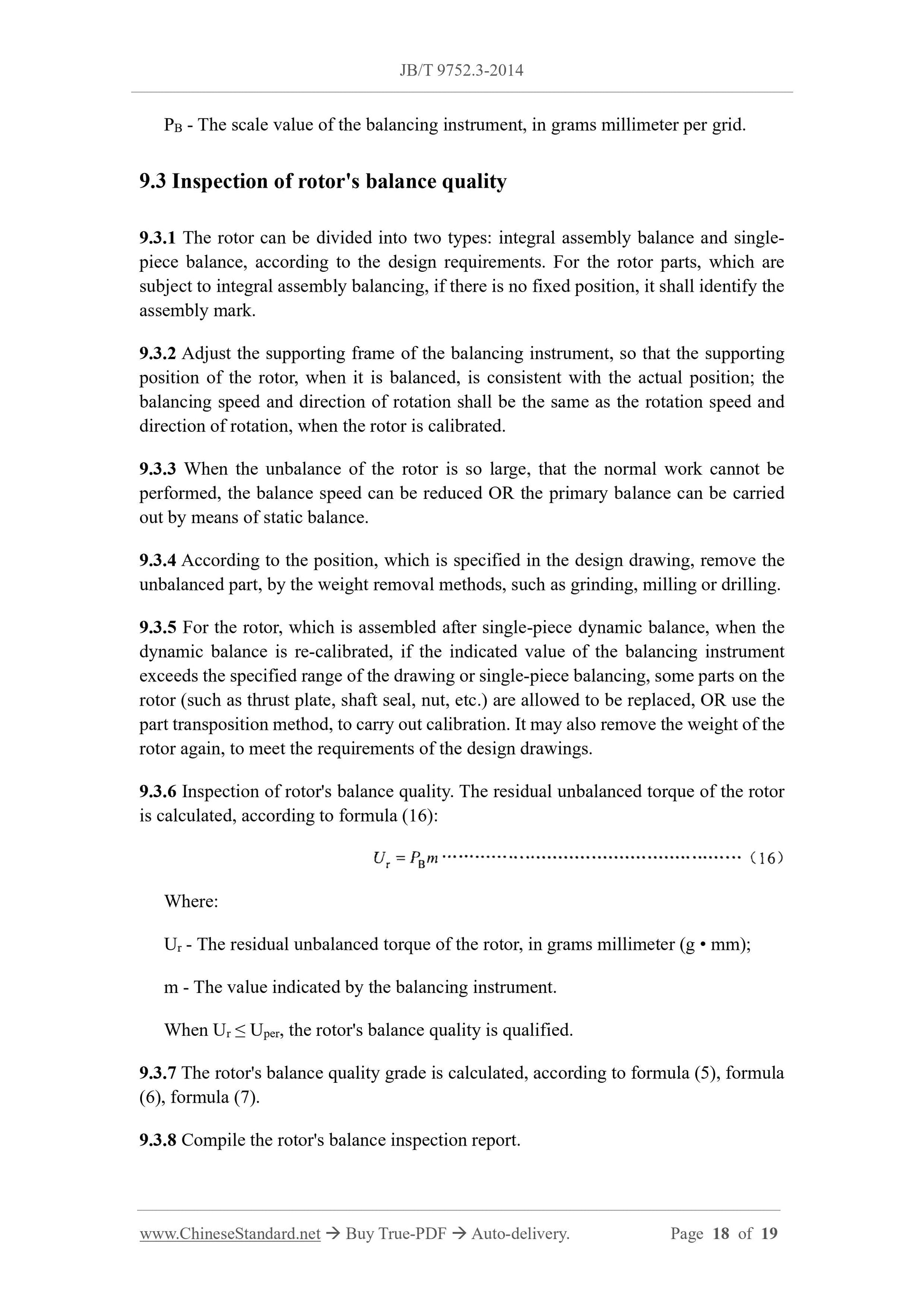
9.3.6 Inspection of rotor's balance quality. The residual unbalanced torque of the rotor
is calculated, according to formula (16):
Where:
Ur - The residual unbalanced torque of the rotor, in grams millimeter (g • mm);
m - The value indicated by the balancing instrument.
When Ur ≤ Uper, the rotor's balance quality is qualified.
9.3.7 The rotor's balance quality grade is calculated, according to formula (5), formula
(6), formula (7).
9.3.8 Compile the rotor's balance inspection report.
JB/T 9752.3-2014
MECHANICAL INDUSTRY STANDARD
OF THE PEOPLE’S REPUBLIC OF CHINA
ICS 27.020
J 91
Filing No.: 45824-2014
Replacing JB/T 9752.3-2004
Turbochargers - Part 3: Balance quality requirements and
check methods of rotors
ISSUED ON: MAY 06, 2014
IMPLEMENTED ON: OCTOBER 01, 2014
Issued by: Ministry of Industry and Information Technology of PRC
Table of Contents
Foreword ... 3
1 Scope ... 5
2 Normative references ... 5
3 Terms and definitions... 5
4 Overview of balance technology ... 7
4.1 Static unbalance ... 7
4.2 Couple unbalance ... 8
4.3 Dynamic unbalance ... 9
4.4 Unbalanced eccentric speed ... 10
4.5 Balance quality grade ... 10
5 Balance quality grade of rigid rotor ... 11
6 Grade of balance quality of flexible rotor and balance quality of core rotor assembly
... 11
7 Limits of balance deviation ... 13
8 Assignment of the allowable unbalance on the rotor correction plane ... 13
8.1 Single-sided balance ... 13
8.2 Double-sided balance ... 13
8.3 Determination of allowable residual unbalance ... 14
8.4 Rotor's balancing procedure ... 15
9 Balance inspection method of rotor ... 16
9.1 Calibration rotor ... 16
9.2 Calibration of balancing instrument's accuracy ... 16
9.3 Inspection of rotor's balance quality ... 18
Appendix A (Informative) Marking method of rotor's balance quality grade of
supercharger on drawing ... 19
Turbochargers - Part 3: Balance quality requirements and
check methods of rotors
1 Scope
This Part of JB/T 9752 specifies the rotor balance quality grade, the calculation and
verification method of the unbalance distribution on the two correction planes, the
balance limit of the core rotor assembly, the marking method on the drawing, of the
turbocharger (hereinafter referred to as the supercharger).
This Part describes the dynamic balancing of single-piece and core rotor assembly for
various types of supercharger rotors.
2 Normative references
The following documents are essential to the application of this document. For the dated
documents, only the versions with the dates indicated are applicable to this document;
for the undated documents, only the latest version (including all the amendments) is
applicable to this standard.
GB/T 4201 Description verification and evaluation of balancing machines
GB/T 7184 Small and medium power diesel engines - Measurement and evaluation
of vibration
GB/T 9239.1-2006 Mechanical vibration - Balance quality requirements for rotors
in a constant (rigid) state - Part 1: Specification and verification of balance
tolerances
JIS B 0905-1992 Rotating machines - Balance quality requirements of rigid rotors
3 Terms and definitions
The terms and definitions, as defined in GB/T 9239.1-2006, as well as the following
terms and definitions, apply to this document.
3.1
Balancing
Check and, if necessary, adjust the rotor mass distribution, to ensure that the residual
unbalance or journal vibration and/or the force acting on the bearing is within
specified limits, at the corresponding operating speed frequency.
3.2
Unbalance
The state of the rotor, when the vibration force or motion, which is caused by the
centrifugal force due to the rotation of the rotor, acts on the bearing.
3.3
Residual unbalance
The residual unbalance on the rotor, after balancing.
3.4
Couple unbalance
A moment unbalance, which is formed by a pair of unbalance vectors of equal
magnitude and opposite phase angles, in two spaced radial planes.
3.5
Dynamic unbalance
The state of any position of the central primary inertial axis, as relative to the axis.
3.6
Balance quality
A quantity, which is used to express the degree of balance of a rigid rotor. Its value
is the product of the rotor centroid offset multiplied by the rotor speed.
3.7
Rigid rotor
A rotor, whose working speed is lower than the first-order critical speed of the rotor
shaft.
3.8
Flexible rotor
A rotor, whose working speed is higher than the first-order critical speed of the rotor
of the pressure roller is still > 0.015 mm, after 360° rotation, the parts on the shaft shall
be replaced, to repeat the above balancing steps.
8.4.3 Balancing of core rotor assembly
Install the combined and dynamically balanced rotor into the intermediate shell. Align
the assembly marks. Tighten the end nut, to form the core rotor assembly. Then carry
out the dynamic balance of the core rotor combination. At any rotational speed, its
vibration acceleration g or vibration velocity V shall not exceed the specified value,
which is specified in Figure 5. If it exceeds, it can be corrected, by removing the weight
from the edge of the end nut, in the angular direction indicated by the balancing machine.
9 Balance inspection method of rotor
9.1 Calibration rotor
9.1.1 Make a rotor, which has the same mass and consistent support position as the
supercharger's rotor, as well as good rigidity; OR select a rotor in the product as the
calibration rotor. Put the calibration rotor on the balancing machine, on the production
line or a balancing machine, which has a higher precision, for calibration. The residual
unbalance of the calibration rotor shall reach the minimum value (close to zero), which
can be reflected by the balancing instrument. Verified calibration rotors shall be
properly stored, to prevent corrosion and deformation. For single-piece and small batch
of products, it is allowed to not keep the calibration rotor.
9.1.2 Calibration rotor shall be calibrated, at the rotating speed of the balancing machine,
which has a higher sensitivity.
9.1.3 The support position and direction of rotation, during calibrating by the calibration
ro...
Delivery: 9 seconds. Download (& Email) true-PDF + Invoice.
Get Quotation: Click JB/T 9752.3-2014 (Self-service in 1-minute)
Historical versions (Master-website): JB/T 9752.3-2014
Preview True-PDF (Reload/Scroll-down if blank)
JB/T 9752.3-2014
MECHANICAL INDUSTRY STANDARD
OF THE PEOPLE’S REPUBLIC OF CHINA
ICS 27.020
J 91
Filing No.: 45824-2014
Replacing JB/T 9752.3-2004
Turbochargers - Part 3: Balance quality requirements and
check methods of rotors
ISSUED ON: MAY 06, 2014
IMPLEMENTED ON: OCTOBER 01, 2014
Issued by: Ministry of Industry and Information Technology of PRC
Table of Contents
Foreword ... 3
1 Scope ... 5
2 Normative references ... 5
3 Terms and definitions... 5
4 Overview of balance technology ... 7
4.1 Static unbalance ... 7
4.2 Couple unbalance ... 8
4.3 Dynamic unbalance ... 9
4.4 Unbalanced eccentric speed ... 10
4.5 Balance quality grade ... 10
5 Balance quality grade of rigid rotor ... 11
6 Grade of balance quality of flexible rotor and balance quality of core rotor assembly
... 11
7 Limits of balance deviation ... 13
8 Assignment of the allowable unbalance on the rotor correction plane ... 13
8.1 Single-sided balance ... 13
8.2 Double-sided balance ... 13
8.3 Determination of allowable residual unbalance ... 14
8.4 Rotor's balancing procedure ... 15
9 Balance inspection method of rotor ... 16
9.1 Calibration rotor ... 16
9.2 Calibration of balancing instrument's accuracy ... 16
9.3 Inspection of rotor's balance quality ... 18
Appendix A (Informative) Marking method of rotor's balance quality grade of
supercharger on drawing ... 19
Turbochargers - Part 3: Balance quality requirements and
check methods of rotors
1 Scope
This Part of JB/T 9752 specifies the rotor balance quality grade, the calculation and
verification method of the unbalance distribution on the two correction planes, the
balance limit of the core rotor assembly, the marking method on the drawing, of the
turbocharger (hereinafter referred to as the supercharger).
This Part describes the dynamic balancing of single-piece and core rotor assembly for
various types of supercharger rotors.
2 Normative references
The following documents are essential to the application of this document. For the dated
documents, only the versions with the dates indicated are applicable to this document;
for the undated documents, only the latest version (including all the amendments) is
applicable to this standard.
GB/T 4201 Description verification and evaluation of balancing machines
GB/T 7184 Small and medium power diesel engines - Measurement and evaluation
of vibration
GB/T 9239.1-2006 Mechanical vibration - Balance quality requirements for rotors
in a constant (rigid) state - Part 1: Specification and verification of balance
tolerances
JIS B 0905-1992 Rotating machines - Balance quality requirements of rigid rotors
3 Terms and definitions
The terms and definitions, as defined in GB/T 9239.1-2006, as well as the following
terms and definitions, apply to this document.
3.1
Balancing
Check and, if necessary, adjust the rotor mass distribution, to ensure that the residual
unbalance or journal vibration and/or the force acting on the bearing is within
specified limits, at the corresponding operating speed frequency.
3.2
Unbalance
The state of the rotor, when the vibration force or motion, which is caused by the
centrifugal force due to the rotation of the rotor, acts on the bearing.
3.3
Residual unbalance
The residual unbalance on the rotor, after balancing.
3.4
Couple unbalance
A moment unbalance, which is formed by a pair of unbalance vectors of equal
magnitude and opposite phase angles, in two spaced radial planes.
3.5
Dynamic unbalance
The state of any position of the central primary inertial axis, as relative to the axis.
3.6
Balance quality
A quantity, which is used to express the degree of balance of a rigid rotor. Its value
is the product of the rotor centroid offset multiplied by the rotor speed.
3.7
Rigid rotor
A rotor, whose working speed is lower than the first-order critical speed of the rotor
shaft.
3.8
Flexible rotor
A rotor, whose working speed is higher than the first-order critical speed of the rotor
of the pressure roller is still > 0.015 mm, after 360° rotation, the parts on the shaft shall
be replaced, to repeat the above balancing steps.
8.4.3 Balancing of core rotor assembly
Install the combined and dynamically balanced rotor into the intermediate shell. Align
the assembly marks. Tighten the end nut, to form the core rotor assembly. Then carry
out the dynamic balance of the core rotor combination. At any rotational speed, its
vibration acceleration g or vibration velocity V shall not exceed the specified value,
which is specified in Figure 5. If it exceeds, it can be corrected, by removing the weight
from the edge of the end nut, in the angular direction indicated by the balancing machine.
9 Balance inspection method of rotor
9.1 Calibration rotor
9.1.1 Make a rotor, which has the same mass and consistent support position as the
supercharger's rotor, as well as good rigidity; OR select a rotor in the product as the
calibration rotor. Put the calibration rotor on the balancing machine, on the production
line or a balancing machine, which has a higher precision, for calibration. The residual
unbalance of the calibration rotor shall reach the minimum value (close to zero), which
can be reflected by the balancing instrument. Verified calibration rotors shall be
properly stored, to prevent corrosion and deformation. For single-piece and small batch
of products, it is allowed to not keep the calibration rotor.
9.1.2 Calibration rotor shall be calibrated, at the rotating speed of the balancing machine,
which has a higher sensitivity.
9.1.3 The support position and direction of rotation, during calibrating by the calibration
rotor, shall be consistent with the working state of the product rotor.
9.1.4 Calibration rotor shall be inspected regularly; the validity period is one year.
9.2 Calibration of balancing instrument's accuracy
9.2.1 Add the test weight unbalance to the calibration rotor. Make calculation, according
to formula (13):
Where:
Uw - The unbalance of the test weight, in grams millimeters (g • mm).
PB - The scale value of the balancing instrument, in grams millimeter per grid.
9.3 Inspection of rotor's balance quality
9.3.1 The rotor can be divided into two types: integral assembly balance and single-
piece balance, according to the design requirements. For the rotor parts, which are
subject to integral assembly balancing, if there is no fixed position, it shall identify the
assembly mark.
9.3.2 Adjust the supporting frame of the balancing instrument, so that the supporting
position of the rotor, when it is balanced, is consistent with the actual position; the
balancing speed and direction of rotation shall be the same as the rotation speed and
direction of rotation, when the rotor is calibrated.
9.3.3 When the unbalance of the rotor is so large, that the normal work cannot be
performed, the balance speed can be reduced OR the primary balance can be carried
out by means of static balance.
9.3.4 According to the position, which is specified in the design drawing, remove the
unbalanced part, by the weight removal methods, such as grinding, milling or drilling.
9.3.5 For the rotor, which is assembled after single-piece dynamic balance, when the
dynamic balance is re-calibrated, if the indicated value of the balancing instrument
exceeds the specified range of the drawing or single-piece balancing, some parts on the
rotor (such as thrust plate, shaft seal, nut, etc.) are allowed to be replaced, OR use the
part transposition method, to carry out calibration. It may also remove the weight of the
rotor again, to meet the requirements of the design drawings.
9.3.6 Inspection of rotor's balance quality. The residual unbalanced torque of the rotor
is calculated, according to formula (16):
Where:
Ur - The residual unbalanced torque of the rotor, in grams millimeter (g • mm);
m - The value indicated by the balancing instrument.
When Ur ≤ Uper, the rotor's balance quality is qualified.
9.3.7 The rotor's balance quality grade is calculated, according to formula (5), formula
(6), formula (7).
9.3.8 Compile the rotor's balance inspection report.
JB/T 9752.3-2014
MECHANICAL INDUSTRY STANDARD
OF THE PEOPLE’S REPUBLIC OF CHINA
ICS 27.020
J 91
Filing No.: 45824-2014
Replacing JB/T 9752.3-2004
Turbochargers - Part 3: Balance quality requirements and
check methods of rotors
ISSUED ON: MAY 06, 2014
IMPLEMENTED ON: OCTOBER 01, 2014
Issued by: Ministry of Industry and Information Technology of PRC
Table of Contents
Foreword ... 3
1 Scope ... 5
2 Normative references ... 5
3 Terms and definitions... 5
4 Overview of balance technology ... 7
4.1 Static unbalance ... 7
4.2 Couple unbalance ... 8
4.3 Dynamic unbalance ... 9
4.4 Unbalanced eccentric speed ... 10
4.5 Balance quality grade ... 10
5 Balance quality grade of rigid rotor ... 11
6 Grade of balance quality of flexible rotor and balance quality of core rotor assembly
... 11
7 Limits of balance deviation ... 13
8 Assignment of the allowable unbalance on the rotor correction plane ... 13
8.1 Single-sided balance ... 13
8.2 Double-sided balance ... 13
8.3 Determination of allowable residual unbalance ... 14
8.4 Rotor's balancing procedure ... 15
9 Balance inspection method of rotor ... 16
9.1 Calibration rotor ... 16
9.2 Calibration of balancing instrument's accuracy ... 16
9.3 Inspection of rotor's balance quality ... 18
Appendix A (Informative) Marking method of rotor's balance quality grade of
supercharger on drawing ... 19
Turbochargers - Part 3: Balance quality requirements and
check methods of rotors
1 Scope
This Part of JB/T 9752 specifies the rotor balance quality grade, the calculation and
verification method of the unbalance distribution on the two correction planes, the
balance limit of the core rotor assembly, the marking method on the drawing, of the
turbocharger (hereinafter referred to as the supercharger).
This Part describes the dynamic balancing of single-piece and core rotor assembly for
various types of supercharger rotors.
2 Normative references
The following documents are essential to the application of this document. For the dated
documents, only the versions with the dates indicated are applicable to this document;
for the undated documents, only the latest version (including all the amendments) is
applicable to this standard.
GB/T 4201 Description verification and evaluation of balancing machines
GB/T 7184 Small and medium power diesel engines - Measurement and evaluation
of vibration
GB/T 9239.1-2006 Mechanical vibration - Balance quality requirements for rotors
in a constant (rigid) state - Part 1: Specification and verification of balance
tolerances
JIS B 0905-1992 Rotating machines - Balance quality requirements of rigid rotors
3 Terms and definitions
The terms and definitions, as defined in GB/T 9239.1-2006, as well as the following
terms and definitions, apply to this document.
3.1
Balancing
Check and, if necessary, adjust the rotor mass distribution, to ensure that the residual
unbalance or journal vibration and/or the force acting on the bearing is within
specified limits, at the corresponding operating speed frequency.
3.2
Unbalance
The state of the rotor, when the vibration force or motion, which is caused by the
centrifugal force due to the rotation of the rotor, acts on the bearing.
3.3
Residual unbalance
The residual unbalance on the rotor, after balancing.
3.4
Couple unbalance
A moment unbalance, which is formed by a pair of unbalance vectors of equal
magnitude and opposite phase angles, in two spaced radial planes.
3.5
Dynamic unbalance
The state of any position of the central primary inertial axis, as relative to the axis.
3.6
Balance quality
A quantity, which is used to express the degree of balance of a rigid rotor. Its value
is the product of the rotor centroid offset multiplied by the rotor speed.
3.7
Rigid rotor
A rotor, whose working speed is lower than the first-order critical speed of the rotor
shaft.
3.8
Flexible rotor
A rotor, whose working speed is higher than the first-order critical speed of the rotor
of the pressure roller is still > 0.015 mm, after 360° rotation, the parts on the shaft shall
be replaced, to repeat the above balancing steps.
8.4.3 Balancing of core rotor assembly
Install the combined and dynamically balanced rotor into the intermediate shell. Align
the assembly marks. Tighten the end nut, to form the core rotor assembly. Then carry
out the dynamic balance of the core rotor combination. At any rotational speed, its
vibration acceleration g or vibration velocity V shall not exceed the specified value,
which is specified in Figure 5. If it exceeds, it can be corrected, by removing the weight
from the edge of the end nut, in the angular direction indicated by the balancing machine.
9 Balance inspection method of rotor
9.1 Calibration rotor
9.1.1 Make a rotor, which has the same mass and consistent support position as the
supercharger's rotor, as well as good rigidity; OR select a rotor in the product as the
calibration rotor. Put the calibration rotor on the balancing machine, on the production
line or a balancing machine, which has a higher precision, for calibration. The residual
unbalance of the calibration rotor shall reach the minimum value (close to zero), which
can be reflected by the balancing instrument. Verified calibration rotors shall be
properly stored, to prevent corrosion and deformation. For single-piece and small batch
of products, it is allowed to not keep the calibration rotor.
9.1.2 Calibration rotor shall be calibrated, at the rotating speed of the balancing machine,
which has a higher sensitivity.
9.1.3 The support position and direction of rotation, during calibrating by the calibration
ro...
Share