1
/
of
12
PayPal, credit cards. Download editable-PDF and invoice in 1 second!
JGJ/T 231-2021 English PDF (JGJ/T231-2021)
JGJ/T 231-2021 English PDF (JGJ/T231-2021)
Regular price
$1,405.00 USD
Regular price
Sale price
$1,405.00 USD
Unit price
/
per
Shipping calculated at checkout.
Couldn't load pickup availability
Delivery: 3 seconds. Download true-PDF + Invoice.
Get QUOTATION in 1-minute: Click JGJ/T 231-2021
Historical versions: JGJ/T 231-2021
Preview True-PDF (Reload/Scroll if blank)
JGJ/T 231-2021: Technical standard for safety of disk locksteel tubular scaffold in construction
JGJ/T 231-2021
UDC JGJ
NATIONAL STANDARD OF THE
PEOPLE’S REPUBLIC OF CHINA
P JGJ/T 231-2021
Replacing J 1128-2021
Technical standard for safety of disk lock steel tubular
scaffold in construction
ISSUED ON: JUNE 30, 2021
IMPLEMENTED ON: OCTOBER 01, 2021
Issued by: Ministry of Housing and Urban-Rural Development of the People's
Republic of China
Table of Contents
Foreword ... 4
1 General provisions ... 7
2 Terms and symbols ... 7
2.1 Terms ... 7
2.2 Symbols ... 9
3 Basic requirements ... 12
4 Loads ... 13
4.1 Load classification ... 13
4.2 Characteristic value of loads ... 14
4.3 Subentry coefficient of loads ... 16
4.4 Combination of loads effects ... 17
5 Structural designs ... 18
5.1 General requirements ... 18
5.2 Foundation bearing capacity calculation ... 20
5.3 Calculation of shoring scaffold ... 21
5.4 Calculation of operation scaffold ... 23
5.5 Calculation of component ... 26
6 Construction requirements ... 27
6.1 General requirements ... 27
6.2 Shoring scaffold ... 27
6.3 Operation scaffold ... 32
7 Installation and disassembly ... 34
7.1 Preparation for construction ... 34
7.2 Construction scheme ... 35
7.3 Ground and foundation ... 35
7.4 Installation and disassembly of shoring scaffold ... 36
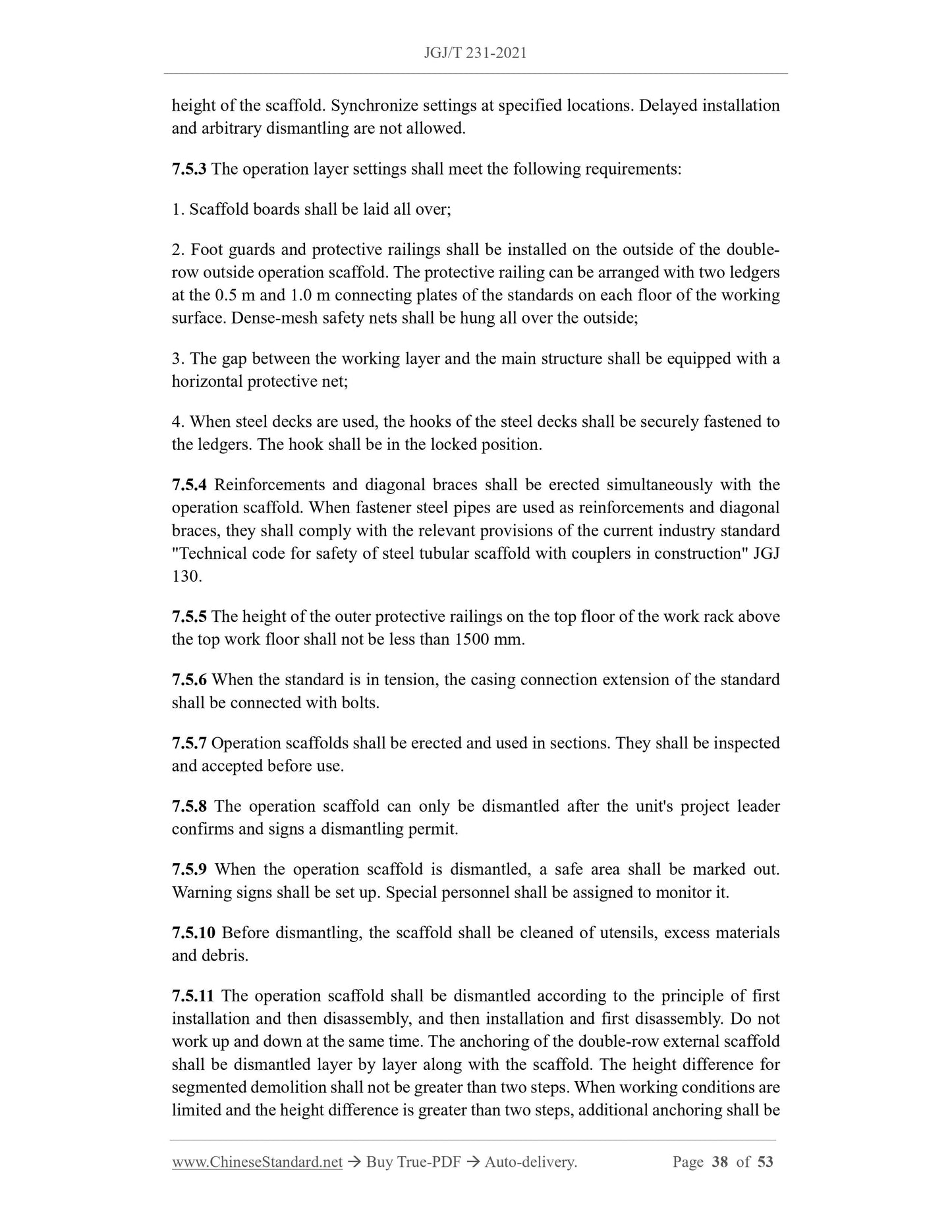
7.5 Installation and disassembly of operation scaffold ... 37
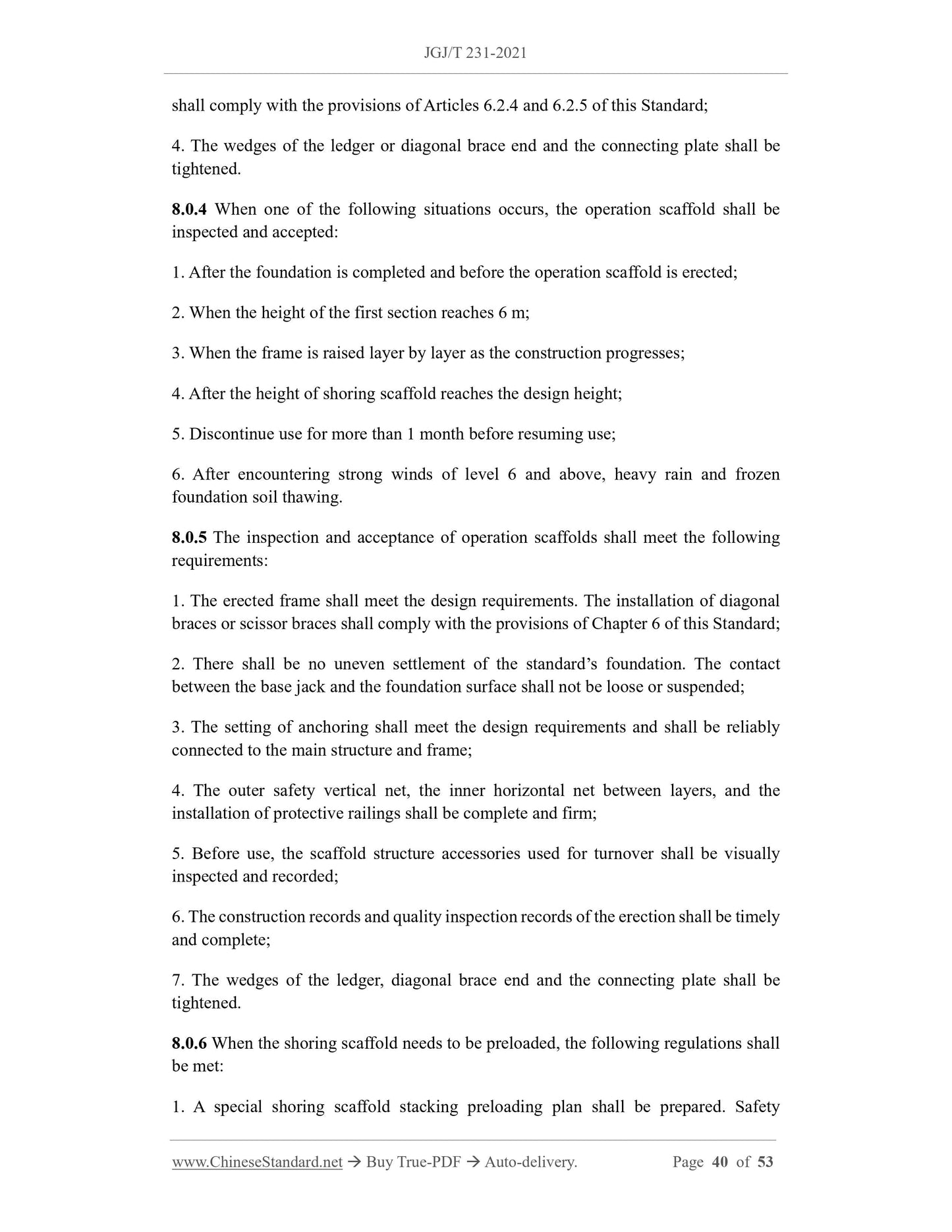
8 Inspection and acceptance ... 39
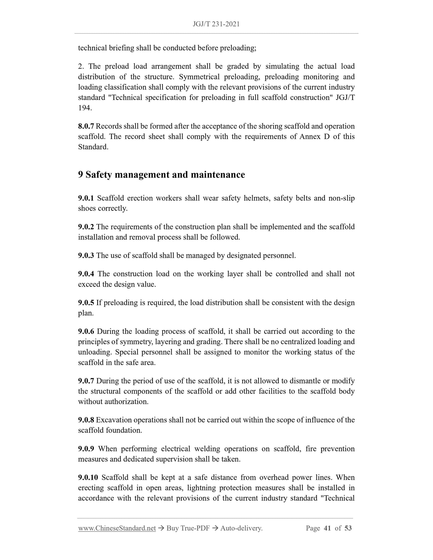
9 Safety management and maintenance ... 41
Annex A Calculating Coefficients of Wind Load ... 43
Annex B Design parameters ... 45
Annex C Stability coefficients for axial compression components... 46
Annex D Construction acceptance record sheets for scaffold ... 48
Explanation of wording in this Standard ... 52
List of quoted standards ... 53
Technical standard for safety of disk lock steel tubular
scaffold in construction
1 General provisions
1.0.1 This Standard is formulated to ensure that the design, installation, dismantling,
use and management of disk lock steel tubular scaffold are technologically advanced,
economically reasonable, safe and applicable.
1.0.2 This Standard applies to the design, installation, dismantling, use and management
of disk lock steel tubular scaffold in construction and municipal engineering.
1.0.3 In addition to complying with this Standard, the design, installation, dismantling,
use and management of disk lock steel tubular scaffold shall also comply with the
provisions of relevant national standards.
2 Terms and symbols
2.1 Terms
2.1.1 disk lock steel tubular scaffold
According to the purpose of use, it can be divided into shoring scaffold and operation
scaffold. A structural frame that can withstand corresponding loads and has operational
safety and protection functions, in which the standards are connected by outer tube or
inner tube, ledgers and diagonal braces are snapped into the connecting plate by the use
of rod end ledger or diagonal brace end, connected with wedges, is referred to as a
scaffold.
2.1.2 shoring scaffold
It is a disk lock steel tubular scaffold that is supported on the ground or structure and
can withstand various loads. It has safety protection functions and provides support and
working platform for building construction. It includes shoring scaffold and structural
erection supports for concrete construction.
2.1.3 operation scaffold
It is a disk lock steel tubular scaffold that is supported on the ground, buildings or
attached to engineering structures to provide a working platform and safety protection
for construction.
FR - Design value of vertical force acting on the connecting plate;
MR - Anti-overturning moment of the scaffold under the design load;
MT - Overturning moment of the scaffold under the design load;
Mw - Bending moment due to wind load design value;
Mwk - Bending moment caused by characteristic value of wind load;
N - Design value of standard’s axial force;
N0 - Axial force generated by the out-of-plane deformation of the scaffold due to the
constraints of the anchoring;
Nk - Standard combination value of the axial force transmitted from the standard to the
top surface of the foundation;
Nl - Design value of axial force of anchoring;
Nlw - Design value of axial force of anchoring s caused by wind load;
∑NGk - Sum of the axial force of the standard generated by the permanent load
characteristic value;
∑NQk - Sum of the axial force of the standard generated by the variable load
characteristic value;
Pk - Average pressure at the bottom of the standard’s foundation corresponding to the
standard combination of load effects
R - Design value of scaffold resistance;
S - Effect design value of scaffold calculated based on basic load combinations;
w0 - Basic wind pressure value;
wk - Wind load characteristic value.
2.2.2 Material properties and resistance
E - Elastic modulus of steel;
f - Design values for tensile, compressive and flexural strength of steel;
fa - Characteristic value of foundation bearing capacity;
Qb - Design value of connecting plate shear bearing capacity;
Rc - Design value of anti-slip bearing capacity of fasteners’
[v] - Allowable deflection.
2.2.3 Geometric parameters
A - Cross-sectional area;
Ag - Base bottom area corresponding to base jack;
An - Net cross-sectional area of anchoring;
a - Distance from head jack support point to center line of ledger;
Hl - Vertical spacing of anchoring;
h - Frame lift height (take the distance between connecting plate on the standard as the
modulus);
h’ - Top step distance of the frame (take the distance between connecting plate on the
standard as the modulus);
I - Sectional moment of inertia;
i - Radius of gyration of section;
Ll - Horizontal spacing between anchorings;
l0 - Calculated length of standard;
la - Vertical distance of standard;
W - Section modulus.
2.2.4 Calculation coefficients
k - Reduction coefficient for the calculated length of the cantilever end of the shoring
scaffold;
Φ - Windshield coefficient;
βH - Adjustment coefficient for the height of shoring scaffold of the shoring scaffold;
γ - Correction coefficient for the lift height of the top layer of the frame;
γ0 - Importance coefficient of scaffold structure;
γG - Permanent load component coefficient;
γQ - Variable load coefficient;
γR - Adjustment coefficient for bearing capacity design value;
arranged in a staggered manner with standards of different lengths. The bottom of the
standard shall be equipped with a base jack or pad.
6.3.4 When setting up a pedestrian passage with double rows of external work racks,
support beams shall be erected on the upper part of the passage. The size of the cross-
beam section shall be calculated and determined based on the span and the load it will
bear. Diagonal braces shall be added to the work racks on both sides of the passage. A
closed protective board shall be laid on the top of the opening. Safety nets shall be set
up on both sides. Safety warning and anti-collision facilities shall be installed at
openings where motor vehicles pass.
6.3.5 Vertical diagonal braces shall be installed on the outer facade of double-row work
racks and shall meet the following requirements:
1. At the corners of the scaffold and at the end of the open scaffold, diagonal braces
shall be continuously installed from the bottom to the top of the scaffold body.
2. A vertical or diagonal continuous diagonal brace shall be installed ever...
Get QUOTATION in 1-minute: Click JGJ/T 231-2021
Historical versions: JGJ/T 231-2021
Preview True-PDF (Reload/Scroll if blank)
JGJ/T 231-2021: Technical standard for safety of disk locksteel tubular scaffold in construction
JGJ/T 231-2021
UDC JGJ
NATIONAL STANDARD OF THE
PEOPLE’S REPUBLIC OF CHINA
P JGJ/T 231-2021
Replacing J 1128-2021
Technical standard for safety of disk lock steel tubular
scaffold in construction
ISSUED ON: JUNE 30, 2021
IMPLEMENTED ON: OCTOBER 01, 2021
Issued by: Ministry of Housing and Urban-Rural Development of the People's
Republic of China
Table of Contents
Foreword ... 4
1 General provisions ... 7
2 Terms and symbols ... 7
2.1 Terms ... 7
2.2 Symbols ... 9
3 Basic requirements ... 12
4 Loads ... 13
4.1 Load classification ... 13
4.2 Characteristic value of loads ... 14
4.3 Subentry coefficient of loads ... 16
4.4 Combination of loads effects ... 17
5 Structural designs ... 18
5.1 General requirements ... 18
5.2 Foundation bearing capacity calculation ... 20
5.3 Calculation of shoring scaffold ... 21
5.4 Calculation of operation scaffold ... 23
5.5 Calculation of component ... 26
6 Construction requirements ... 27
6.1 General requirements ... 27
6.2 Shoring scaffold ... 27
6.3 Operation scaffold ... 32
7 Installation and disassembly ... 34
7.1 Preparation for construction ... 34
7.2 Construction scheme ... 35
7.3 Ground and foundation ... 35
7.4 Installation and disassembly of shoring scaffold ... 36
7.5 Installation and disassembly of operation scaffold ... 37
8 Inspection and acceptance ... 39
9 Safety management and maintenance ... 41
Annex A Calculating Coefficients of Wind Load ... 43
Annex B Design parameters ... 45
Annex C Stability coefficients for axial compression components... 46
Annex D Construction acceptance record sheets for scaffold ... 48
Explanation of wording in this Standard ... 52
List of quoted standards ... 53
Technical standard for safety of disk lock steel tubular
scaffold in construction
1 General provisions
1.0.1 This Standard is formulated to ensure that the design, installation, dismantling,
use and management of disk lock steel tubular scaffold are technologically advanced,
economically reasonable, safe and applicable.
1.0.2 This Standard applies to the design, installation, dismantling, use and management
of disk lock steel tubular scaffold in construction and municipal engineering.
1.0.3 In addition to complying with this Standard, the design, installation, dismantling,
use and management of disk lock steel tubular scaffold shall also comply with the
provisions of relevant national standards.
2 Terms and symbols
2.1 Terms
2.1.1 disk lock steel tubular scaffold
According to the purpose of use, it can be divided into shoring scaffold and operation
scaffold. A structural frame that can withstand corresponding loads and has operational
safety and protection functions, in which the standards are connected by outer tube or
inner tube, ledgers and diagonal braces are snapped into the connecting plate by the use
of rod end ledger or diagonal brace end, connected with wedges, is referred to as a
scaffold.
2.1.2 shoring scaffold
It is a disk lock steel tubular scaffold that is supported on the ground or structure and
can withstand various loads. It has safety protection functions and provides support and
working platform for building construction. It includes shoring scaffold and structural
erection supports for concrete construction.
2.1.3 operation scaffold
It is a disk lock steel tubular scaffold that is supported on the ground, buildings or
attached to engineering structures to provide a working platform and safety protection
for construction.
FR - Design value of vertical force acting on the connecting plate;
MR - Anti-overturning moment of the scaffold under the design load;
MT - Overturning moment of the scaffold under the design load;
Mw - Bending moment due to wind load design value;
Mwk - Bending moment caused by characteristic value of wind load;
N - Design value of standard’s axial force;
N0 - Axial force generated by the out-of-plane deformation of the scaffold due to the
constraints of the anchoring;
Nk - Standard combination value of the axial force transmitted from the standard to the
top surface of the foundation;
Nl - Design value of axial force of anchoring;
Nlw - Design value of axial force of anchoring s caused by wind load;
∑NGk - Sum of the axial force of the standard generated by the permanent load
characteristic value;
∑NQk - Sum of the axial force of the standard generated by the variable load
characteristic value;
Pk - Average pressure at the bottom of the standard’s foundation corresponding to the
standard combination of load effects
R - Design value of scaffold resistance;
S - Effect design value of scaffold calculated based on basic load combinations;
w0 - Basic wind pressure value;
wk - Wind load characteristic value.
2.2.2 Material properties and resistance
E - Elastic modulus of steel;
f - Design values for tensile, compressive and flexural strength of steel;
fa - Characteristic value of foundation bearing capacity;
Qb - Design value of connecting plate shear bearing capacity;
Rc - Design value of anti-slip bearing capacity of fasteners’
[v] - Allowable deflection.
2.2.3 Geometric parameters
A - Cross-sectional area;
Ag - Base bottom area corresponding to base jack;
An - Net cross-sectional area of anchoring;
a - Distance from head jack support point to center line of ledger;
Hl - Vertical spacing of anchoring;
h - Frame lift height (take the distance between connecting plate on the standard as the
modulus);
h’ - Top step distance of the frame (take the distance between connecting plate on the
standard as the modulus);
I - Sectional moment of inertia;
i - Radius of gyration of section;
Ll - Horizontal spacing between anchorings;
l0 - Calculated length of standard;
la - Vertical distance of standard;
W - Section modulus.
2.2.4 Calculation coefficients
k - Reduction coefficient for the calculated length of the cantilever end of the shoring
scaffold;
Φ - Windshield coefficient;
βH - Adjustment coefficient for the height of shoring scaffold of the shoring scaffold;
γ - Correction coefficient for the lift height of the top layer of the frame;
γ0 - Importance coefficient of scaffold structure;
γG - Permanent load component coefficient;
γQ - Variable load coefficient;
γR - Adjustment coefficient for bearing capacity design value;
arranged in a staggered manner with standards of different lengths. The bottom of the
standard shall be equipped with a base jack or pad.
6.3.4 When setting up a pedestrian passage with double rows of external work racks,
support beams shall be erected on the upper part of the passage. The size of the cross-
beam section shall be calculated and determined based on the span and the load it will
bear. Diagonal braces shall be added to the work racks on both sides of the passage. A
closed protective board shall be laid on the top of the opening. Safety nets shall be set
up on both sides. Safety warning and anti-collision facilities shall be installed at
openings where motor vehicles pass.
6.3.5 Vertical diagonal braces shall be installed on the outer facade of double-row work
racks and shall meet the following requirements:
1. At the corners of the scaffold and at the end of the open scaffold, diagonal braces
shall be continuously installed from the bottom to the top of the scaffold body.
2. A vertical or diagonal continuous diagonal brace shall be installed ever...
Share