1
/
of
8
PayPal, credit cards. Download editable-PDF & invoice in 1 second!
JJF 1561-2016 English PDF (JJF1561-2016)
JJF 1561-2016 English PDF (JJF1561-2016)
Regular price
$160.00 USD
Regular price
Sale price
$160.00 USD
Unit price
/
per
Shipping calculated at checkout.
Couldn't load pickup availability
Delivery: 3 seconds. Download true-PDF + Invoice.
Get QUOTATION in 1-minute: Click JJF 1561-2016
Historical versions: JJF 1561-2016
Preview True-PDF (Reload/Scroll if blank)
JJF 1561-2016: Calibration Specification for Gear Measuring Centers
JJF 1561-2016
JJF
METROLOGICAL TECHNICAL SPECIFICATION
OF THE PEOPLE’S REPUBLIC OF CHINA
Calibration specification for gear measuring centers
ISSUED ON. JUNE 27, 2016
IMPLEMENTED ON. SEPTEMBER 27, 2016
Issued by. General Administration of Quality Supervision Inspection and
Quarantine of PRC
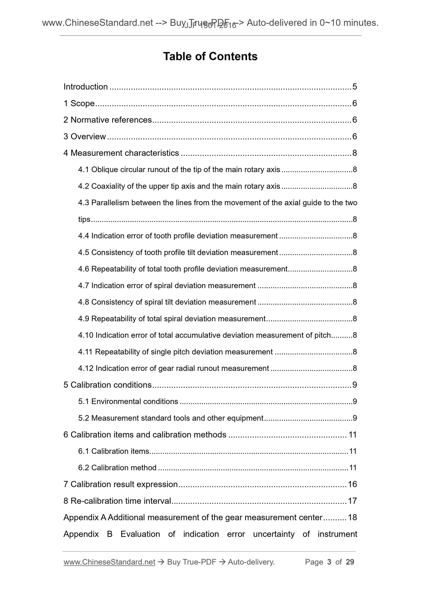
Table of Contents
Introduction ... 5
1 Scope ... 6
2 Normative references ... 6
3 Overview ... 6
4 Measurement characteristics ... 8
4.1 Oblique circular runout of the tip of the main rotary axis ... 8
4.2 Coaxiality of the upper tip axis and the main rotary axis ... 8
4.3 Parallelism between the lines from the movement of the axial guide to the two
tips ... 8
4.4 Indication error of tooth profile deviation measurement ... 8
4.5 Consistency of tooth profile tilt deviation measurement ... 8
4.6 Repeatability of total tooth profile deviation measurement ... 8
4.7 Indication error of spiral deviation measurement ... 8
4.8 Consistency of spiral tilt deviation measurement ... 8
4.9 Repeatability of total spiral deviation measurement ... 8
4.10 Indication error of total accumulative deviation measurement of pitch ... 8
4.11 Repeatability of single pitch deviation measurement ... 8
4.12 Indication error of gear radial runout measurement ... 8
5 Calibration conditions ... 9
5.1 Environmental conditions ... 9
5.2 Measurement standard tools and other equipment ... 9
6 Calibration items and calibration methods ... 11
6.1 Calibration items... 11
6.2 Calibration method ... 11
7 Calibration result expression ... 16
8 Re-calibration time interval... 17
Appendix A Additional measurement of the gear measurement center ... 18
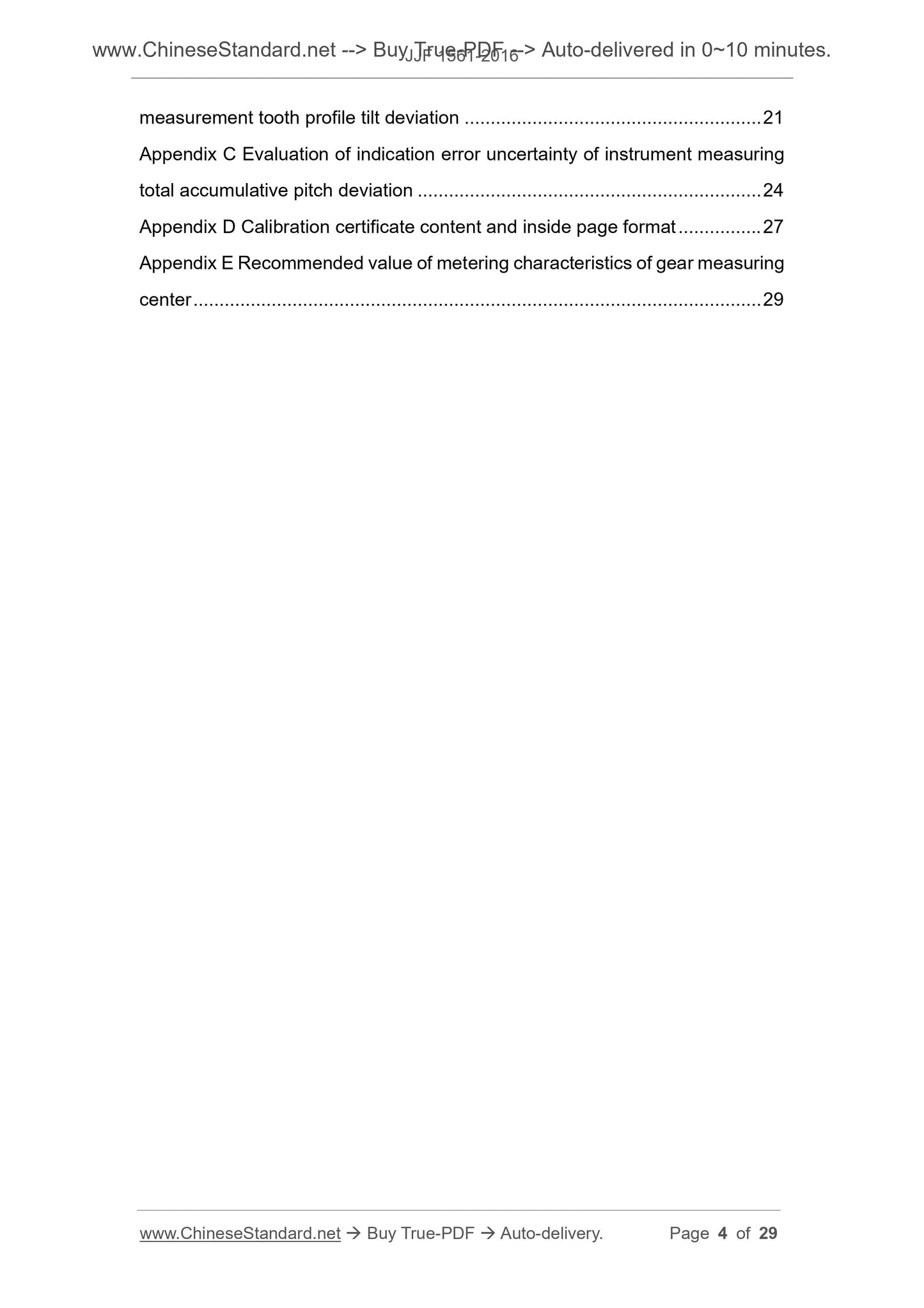
Appendix B Evaluation of indication error uncertainty of instrument
measurement tooth profile tilt deviation ... 21
Appendix C Evaluation of indication error uncertainty of instrument measuring
total accumulative pitch deviation ... 24
Appendix D Calibration certificate content and inside page format ... 27
Appendix E Recommended value of metering characteristics of gear measuring
center ... 29
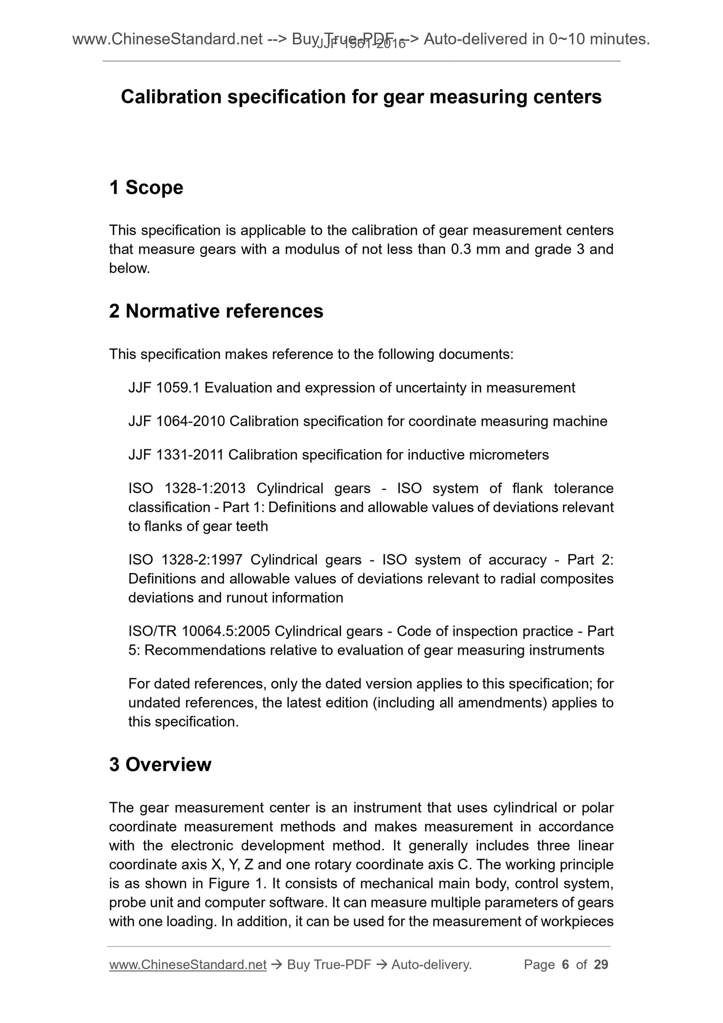
Calibration specification for gear measuring centers
1 Scope
This specification is applicable to the calibration of gear measurement centers
that measure gears with a modulus of not less than 0.3 mm and grade 3 and
below.
2 Normative references
This specification makes reference to the following documents.
JJF 1059.1 Evaluation and expression of uncertainty in measurement
JJF 1064-2010 Calibration specification for coordinate measuring machine
JJF 1331-2011 Calibration specification for inductive micrometers
ISO 1328-1.2013 Cylindrical gears - ISO system of flank tolerance
classification - Part 1. Definitions and allowable values of deviations relevant
to flanks of gear teeth
ISO 1328-2.1997 Cylindrical gears - ISO system of accuracy - Part 2.
Definitions and allowable values of deviations relevant to radial composites
deviations and runout information
ISO/TR 10064.5.2005 Cylindrical gears - Code of inspection practice - Part
5. Recommendations relative to evaluation of gear measuring instruments
For dated references, only the dated version applies to this specification; for
undated references, the latest edition (including all amendments) applies to
this specification.
3 Overview
The gear measurement center is an instrument that uses cylindrical or polar
coordinate measurement methods and makes measurement in accordance
with the electronic development method. It generally includes three linear
coordinate axis X, Y, Z and one rotary coordinate axis C. The working principle
is as shown in Figure 1. It consists of mechanical main body, control system,
probe unit and computer software. It can measure multiple parameters of gears
with one loading. In addition, it can be used for the measurement of workpieces
4 Measurement characteristics
4.1 Oblique circular runout of the tip of the main rotary axis
4.2 Coaxiality of the upper tip axis and the main rotary axis
4.3 Parallelism between the lines from the movement of the
axial guide to the two tips
4.4 Indication error of tooth profile deviation measurement
4.5 Consistency of tooth profile tilt deviation measurement
4.6 Repeatability of total tooth profile deviation measurement
4.7 Indication error of spiral deviation measurement
4.8 Consistency of spiral tilt deviation measurement
4.9 Repeatability of total spiral deviation measurement
4.10 Indication error of total accumulative deviation
measurement of pitch
4.11 Repeatability of single pitch deviation measurement
4.12 Indication error of gear radial runout measurement
Note. The indication error of the probe and the indication error of the coordinate
axis positioning are supplementary measurements for the large-scale gear
measurement center. See Appendix A for details.
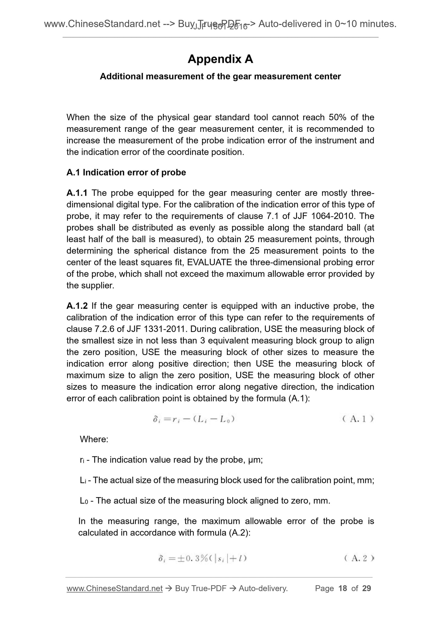
Appendix A
Additional measurement of the gear measurement center
When the size of the physical gear standard tool cannot reach 50% of the
measurement range of the gear measurement center, it is recommended to
increase the measurement of the probe indication error of the instrument and
the indication error of the coordinate position.
A.1 Indication error of probe
A.1.1 The probe equipped for the gear measuring center are mostly three-
dimensional digital type. For the calibration of the indication error of this type of
probe, it may refer to the requirements of clause 7.1 of JJF 1064-2010. The
probes shall be distributed as evenly as possible along the standard ball (at
least half of the ball is measured), to obtain 25 measurement points, through
determining the spherical distance from the 25 measurement points to the
center of the least squares fit, EVALUATE the three-dimensional probing error
of the probe, which shall not exceed the maximum allowable error provided by
the supplier.
A.1.2 If the gear measuring center is equipped with an inductive probe, the
calibration of the indication error of this type can refer to the requirements of
clause 7.2.6 of JJF 1331-2011. During calibration, USE the measuring block of
the smallest size in not less than 3 equivalent measuring block group to align
the zero position, USE the measuring block of other sizes to measure the
indication error along positive direction; then USE the measuring block of
maximum size to align the zero position, USE the measuring block of other
sizes to measure the indication error along negative direction, the indication
error of each calibration point is obtained by the formula (A.1).
Where.
ri - The indication value read by the probe, μm;
Li - The actual size of the measuring block used for the calibration point, mm;
L0 - The actual size of the measuring block aligned to zero, mm.
In the measuring range, the maximum allowable error of the probe is
calculated in accordance with formula (A.2).
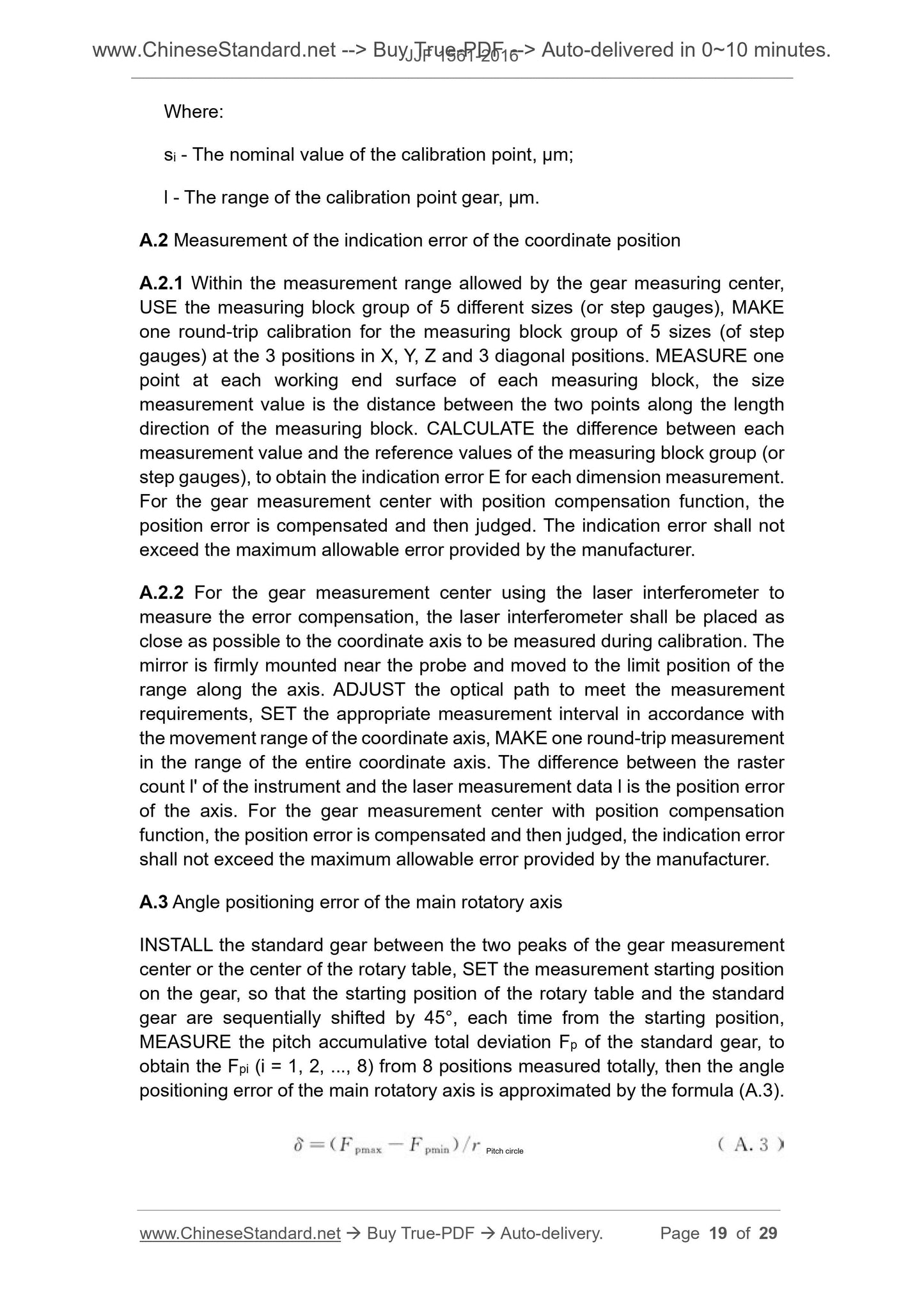
Where.
si - The nominal value of the calibration point, μm;
l - The range of the calibration point gear, μm.
A.2 Measurement of the indication error of the coordinate position
A.2.1 Within the measurement range allowed by the gear measuring center,
USE the measuring block group of 5 different sizes (or step gauges), MAKE
one round-trip calibration for the measuring block group of 5 sizes (of step
gauges) at the 3 positions in X, Y, Z and 3 diagonal positions. MEASURE one
point at each working end surface of each measuring block, the size
measurement value is the distance between th...
Share
