1
/
of
12
PayPal, credit cards. Download editable-PDF and invoice in 1 second!
JJF 1835-2020 English PDF
JJF 1835-2020 English PDF
Regular price
$405.00 USD
Regular price
Sale price
$405.00 USD
Unit price
/
per
Shipping calculated at checkout.
Couldn't load pickup availability
Delivery: 3 seconds. Download true-PDF + Invoice.
Get QUOTATION in 1-minute: Click JJF 1835-2020
Historical versions: JJF 1835-2020
Preview True-PDF (Reload/Scroll if blank)
JJF 1835-2020: Calibration Specification for Remote Sensing Measurement Systems of Vehicle Emission Pollutant
JJF 1835-2020
JJF
METERING TECHNICAL SPECIFICATION
OF THE PEOPLE’S REPUBLIC OF CHINA
Calibration specification for remote sensing
measurement systems of vehicle exhaust
ISSUED ON: JULY 02, 2020
IMPLEMENTED ON: JANUARY 02, 2021
Issued by: State Administration for Market Regulation
Table of Contents
Introduction ... 5
1 Scope ... 6
2 Reference documents ... 6
3 Terms ... 6
3.1 Remote sensing method ... 6
3.2 Vehicle exhaust ... 6
3.3 Opacity ... 6
3.4 Standard reducing light dimmer ... 7
3.5 Background value... 7
4 Overview ... 7
5 Metrological characteristics ... 7
5.1 Exhaust gas measuring device ... 7
5.2 Speed measuring device ... 8
5.3 Road slope measuring device ... 8
5.4 Meteorological parameter measuring device ... 9
6 Calibration conditions ... 9
6.1 Environmental conditions ... 9
6.2 Calibration standards and other equipment ... 9
7 Calibration items and calibration methods ... 11
7.1 Gas measuring device ... 11
7.2 Opacity measuring device ... 13
7.3 Speed measuring device ... 14
7.4 Road slope measuring device ... 17
7.5 Meteorological parameter measuring device ... 17
8 Representation of calibration result ... 19
8.1 Calibration data processing ... 19
8.2 Evaluation of uncertainty of calibration results ... 19
8.3 Calibration certificate ... 20
9 Recalibration time interval ... 20
Appendix A Standard gas and its concentration requirements ... 21
Appendix B Calibration record of remote sensing system for vehicle exhaust
... 22
Appendix C Format of the inside page of the calibration certificate for the remote
sensing system of vehicle exhaust ... 25
Appendix D Example of uncertainty evaluation of indication error calibration for
remote sensing system of vehicle exhaust ... 26
Calibration specification for remote sensing
measurement systems of vehicle exhaust
1 Scope
This specification applies to the calibration of the remote sensing measurement
system for motor vehicle exhaust.
2 Reference documents
This specification refers to the following documents:
HJ 845 Measurement methods and technical requirements for exhaust
pollutants from diesel vehicles in use (remote sensing method)
JB/T 11996 General technical requirements of remote sensing equipment for
motor vehicle exhaust
For dated reference documents, only the dated version applies to this
specification; for undated reference documents, the latest version (including all
amendments) applies to this specification.
3 Terms
3.1 Remote sensing method
A method of remote sensing and measuring the exhaust gas concentration
of a driving motor vehicle using optical principles.
[Source: HJ 845-2017, 3.2, with modification]
3.2 Vehicle exhaust
The gaseous pollutants and particulate matter emitted from the exhaust pipe
of a motor vehicle, which refer to CO, CO2, HC, NO and particulate matter
in this specification.
3.3 Opacity
The flux absorption percentage of the light emitted from the light source
passes through the exhaust plume of the motor vehicle and reaches the light
receiver of the instrument, which is generally represented by the symbol N.
[Source: HJ 845-2017, 3.8, with modification]
3.4 Standard reducing light dimmer
A standard device that uses a physical method to block light from passing
through in accordance with a prescribed ratio, which is the opacity of the
standard reducing light dimmer.
3.5 Background value
The state of ambient gas before remote sensing of motor vehicle exhaust
gas, which refers to the environmental background value.
4 Overview
Remote sensing system for motor vehicle exhaust (hereinafter referred to as
remote sensing system) is a measurement system that uses remote sensing to
detect the exhaust of motor vehicles traveling within a specified speed range
under certain weather conditions and road slopes. It can measure the exhaust
gas value of motor vehicles on the road without affecting the normal driving of
motor vehicles. Its working principle is: the mainframe of the remote sensing
system emits a light beam; when a motor vehicle passes, the exhaust gas
interferes with the light beam; the spectrum, intensity and other characteristics
of the light received by the receiving end will change; this change can reflect
the concentration of the measured exhaust gas or changes in opacity. At
present, the light sources used in the remote sensing system are laser, infrared
heat radiation, ultraviolet light, yellow-green light.
The remote sensing system is mainly composed of exhaust gas measurement
devices (generally including gas measurement devices and opacity
measurement devices for measuring particulate pollutants, or only one of them),
speed measurement devices, road slope measurement devices,
meteorological parameter measurement devices, vehicle number plates
identification system, control and management computer system, etc. Its usage
is divided into the following three types: horizontal mobile remote sensing
system, horizontal fixed remote sensing system, vertical fixed remote sensing
system.
5 Metrological characteristics
5.1 Exhaust gas measuring device
5.1.1 Gas measuring device
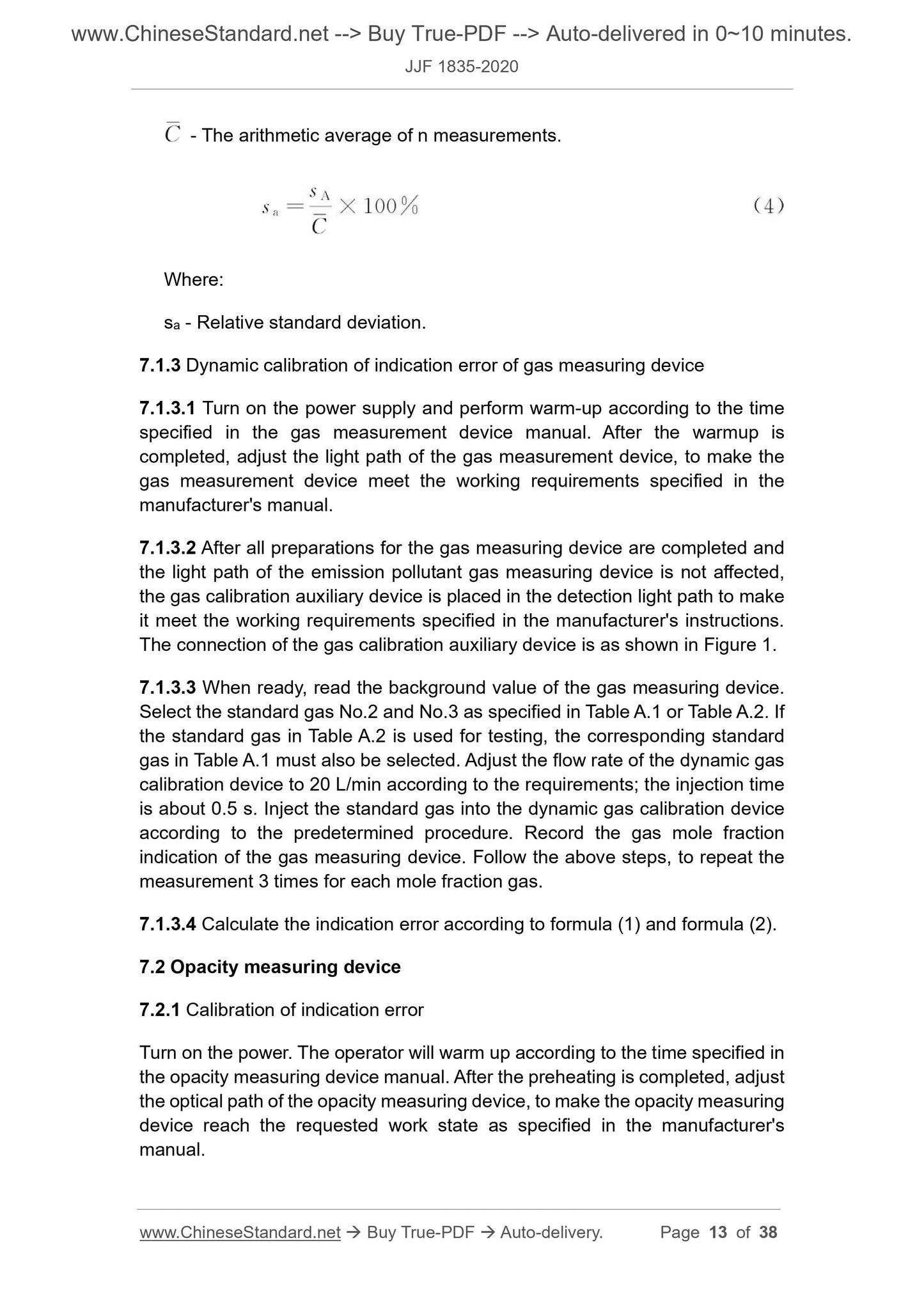
- The arithmetic average of n measurements.
Where:
sa - Relative standard deviation.
7.1.3 Dynamic calibration of indication error of gas measuring device
7.1.3.1 Turn on the power supply and perform warm-up according to the time
specified in the gas measurement device manual. After the warmup is
completed, adjust the light path of the gas measurement device, to make the
gas measurement device meet the working requirements specified in the
manufacturer's manual.
7.1.3.2 After all preparations for the gas measuring device are completed and
the light path of the emission pollutant gas measuring device is not affected,
the gas calibration auxiliary device is placed in the detection light path to make
it meet the working requirements specified in the manufacturer's instructions.
The connection of the gas calibration auxiliary device is as shown in Figure 1.
7.1.3.3 When ready, read the background value of the gas measuring device.
Select the standard gas No.2 and No.3 as specified in Table A.1 or Table A.2. If
the standard gas in Table A.2 is used for testing, the corresponding standard
gas in Table A.1 must also be selected. Adjust the flow rate of the dynamic gas
calibration device to 20 L/min according to the requirements; the injection time
is about 0.5 s. Inject the standard gas into the dynamic gas calibration device
according to the predetermined procedure. Record the gas mole fraction
indication of the gas measuring device. Follow the above steps, to repeat the
measurement 3 times for each mole fraction gas.
7.1.3.4 Calculate the indication error according to formula (1) and formula (2).
7.2 Opacity measuring device
7.2.1 Calibration of indication error
Turn on the power. The operator will warm up according to the time specified in
the opacity measuring device manual. After the preheating is completed, adjust
the optical path of the opacity measuring device, to make the opacity measuring
device reach the requested work state as specified in the manufacturer's
manual.
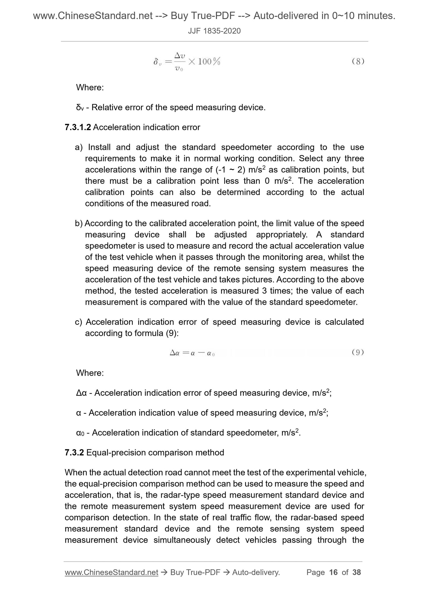
Where:
δv - Relative error of the speed measuring device.
7.3.1.2 Acceleration indication error
a) Install and adjust the standard speedometer according to the use
requirements to make it in normal wor...
Get QUOTATION in 1-minute: Click JJF 1835-2020
Historical versions: JJF 1835-2020
Preview True-PDF (Reload/Scroll if blank)
JJF 1835-2020: Calibration Specification for Remote Sensing Measurement Systems of Vehicle Emission Pollutant
JJF 1835-2020
JJF
METERING TECHNICAL SPECIFICATION
OF THE PEOPLE’S REPUBLIC OF CHINA
Calibration specification for remote sensing
measurement systems of vehicle exhaust
ISSUED ON: JULY 02, 2020
IMPLEMENTED ON: JANUARY 02, 2021
Issued by: State Administration for Market Regulation
Table of Contents
Introduction ... 5
1 Scope ... 6
2 Reference documents ... 6
3 Terms ... 6
3.1 Remote sensing method ... 6
3.2 Vehicle exhaust ... 6
3.3 Opacity ... 6
3.4 Standard reducing light dimmer ... 7
3.5 Background value... 7
4 Overview ... 7
5 Metrological characteristics ... 7
5.1 Exhaust gas measuring device ... 7
5.2 Speed measuring device ... 8
5.3 Road slope measuring device ... 8
5.4 Meteorological parameter measuring device ... 9
6 Calibration conditions ... 9
6.1 Environmental conditions ... 9
6.2 Calibration standards and other equipment ... 9
7 Calibration items and calibration methods ... 11
7.1 Gas measuring device ... 11
7.2 Opacity measuring device ... 13
7.3 Speed measuring device ... 14
7.4 Road slope measuring device ... 17
7.5 Meteorological parameter measuring device ... 17
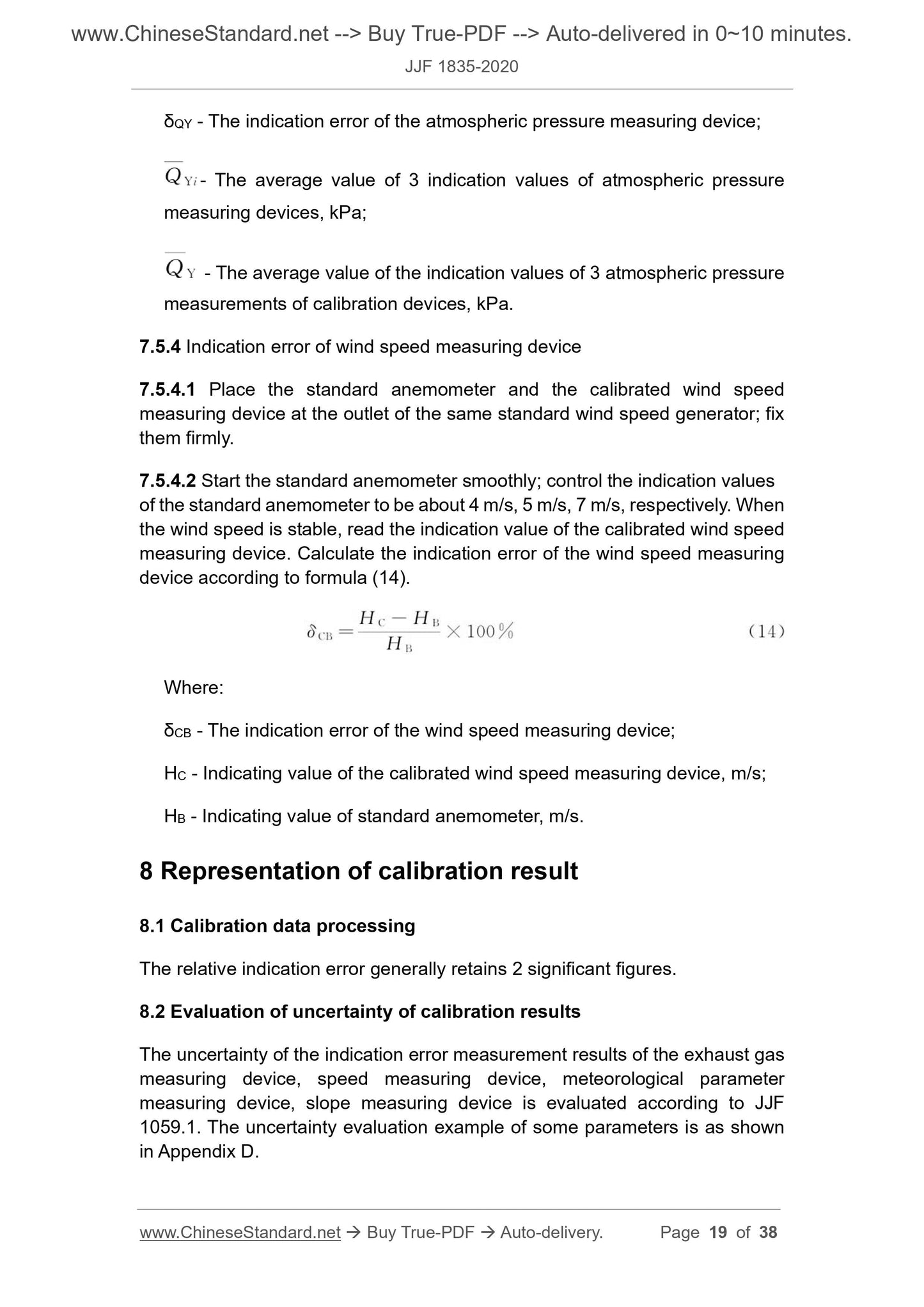
8 Representation of calibration result ... 19
8.1 Calibration data processing ... 19
8.2 Evaluation of uncertainty of calibration results ... 19
8.3 Calibration certificate ... 20
9 Recalibration time interval ... 20
Appendix A Standard gas and its concentration requirements ... 21
Appendix B Calibration record of remote sensing system for vehicle exhaust
... 22
Appendix C Format of the inside page of the calibration certificate for the remote
sensing system of vehicle exhaust ... 25
Appendix D Example of uncertainty evaluation of indication error calibration for
remote sensing system of vehicle exhaust ... 26
Calibration specification for remote sensing
measurement systems of vehicle exhaust
1 Scope
This specification applies to the calibration of the remote sensing measurement
system for motor vehicle exhaust.
2 Reference documents
This specification refers to the following documents:
HJ 845 Measurement methods and technical requirements for exhaust
pollutants from diesel vehicles in use (remote sensing method)
JB/T 11996 General technical requirements of remote sensing equipment for
motor vehicle exhaust
For dated reference documents, only the dated version applies to this
specification; for undated reference documents, the latest version (including all
amendments) applies to this specification.
3 Terms
3.1 Remote sensing method
A method of remote sensing and measuring the exhaust gas concentration
of a driving motor vehicle using optical principles.
[Source: HJ 845-2017, 3.2, with modification]
3.2 Vehicle exhaust
The gaseous pollutants and particulate matter emitted from the exhaust pipe
of a motor vehicle, which refer to CO, CO2, HC, NO and particulate matter
in this specification.
3.3 Opacity
The flux absorption percentage of the light emitted from the light source
passes through the exhaust plume of the motor vehicle and reaches the light
receiver of the instrument, which is generally represented by the symbol N.
[Source: HJ 845-2017, 3.8, with modification]
3.4 Standard reducing light dimmer
A standard device that uses a physical method to block light from passing
through in accordance with a prescribed ratio, which is the opacity of the
standard reducing light dimmer.
3.5 Background value
The state of ambient gas before remote sensing of motor vehicle exhaust
gas, which refers to the environmental background value.
4 Overview
Remote sensing system for motor vehicle exhaust (hereinafter referred to as
remote sensing system) is a measurement system that uses remote sensing to
detect the exhaust of motor vehicles traveling within a specified speed range
under certain weather conditions and road slopes. It can measure the exhaust
gas value of motor vehicles on the road without affecting the normal driving of
motor vehicles. Its working principle is: the mainframe of the remote sensing
system emits a light beam; when a motor vehicle passes, the exhaust gas
interferes with the light beam; the spectrum, intensity and other characteristics
of the light received by the receiving end will change; this change can reflect
the concentration of the measured exhaust gas or changes in opacity. At
present, the light sources used in the remote sensing system are laser, infrared
heat radiation, ultraviolet light, yellow-green light.
The remote sensing system is mainly composed of exhaust gas measurement
devices (generally including gas measurement devices and opacity
measurement devices for measuring particulate pollutants, or only one of them),
speed measurement devices, road slope measurement devices,
meteorological parameter measurement devices, vehicle number plates
identification system, control and management computer system, etc. Its usage
is divided into the following three types: horizontal mobile remote sensing
system, horizontal fixed remote sensing system, vertical fixed remote sensing
system.
5 Metrological characteristics
5.1 Exhaust gas measuring device
5.1.1 Gas measuring device
- The arithmetic average of n measurements.
Where:
sa - Relative standard deviation.
7.1.3 Dynamic calibration of indication error of gas measuring device
7.1.3.1 Turn on the power supply and perform warm-up according to the time
specified in the gas measurement device manual. After the warmup is
completed, adjust the light path of the gas measurement device, to make the
gas measurement device meet the working requirements specified in the
manufacturer's manual.
7.1.3.2 After all preparations for the gas measuring device are completed and
the light path of the emission pollutant gas measuring device is not affected,
the gas calibration auxiliary device is placed in the detection light path to make
it meet the working requirements specified in the manufacturer's instructions.
The connection of the gas calibration auxiliary device is as shown in Figure 1.
7.1.3.3 When ready, read the background value of the gas measuring device.
Select the standard gas No.2 and No.3 as specified in Table A.1 or Table A.2. If
the standard gas in Table A.2 is used for testing, the corresponding standard
gas in Table A.1 must also be selected. Adjust the flow rate of the dynamic gas
calibration device to 20 L/min according to the requirements; the injection time
is about 0.5 s. Inject the standard gas into the dynamic gas calibration device
according to the predetermined procedure. Record the gas mole fraction
indication of the gas measuring device. Follow the above steps, to repeat the
measurement 3 times for each mole fraction gas.
7.1.3.4 Calculate the indication error according to formula (1) and formula (2).
7.2 Opacity measuring device
7.2.1 Calibration of indication error
Turn on the power. The operator will warm up according to the time specified in
the opacity measuring device manual. After the preheating is completed, adjust
the optical path of the opacity measuring device, to make the opacity measuring
device reach the requested work state as specified in the manufacturer's
manual.
Where:
δv - Relative error of the speed measuring device.
7.3.1.2 Acceleration indication error
a) Install and adjust the standard speedometer according to the use
requirements to make it in normal wor...
Share