1
/
of
12
www.ChineseStandard.us -- Field Test Asia Pte. Ltd.
JJG 1033-2007 English PDF
JJG 1033-2007 English PDF
Regular price
$275.00
Regular price
Sale price
$275.00
Unit price
/
per
Shipping calculated at checkout.
Couldn't load pickup availability
JJG 1033-2007: Verification Regulation of Electromagnetic Flowmeters
Delivery: 9 seconds. Download (& Email) true-PDF + Invoice.
Get Quotation: Click JJG 1033-2007 (Self-service in 1-minute)
Historical versions (Master-website): JJG 1033-2007
Preview True-PDF (Reload/Scroll-down if blank)
JJG 1033-2007
JJG
METROLOGICAL VERIFICATION REGULATION
OF THE PEOPLE’S REPUBLIC OF CHINA
Electromagnetic flowmeters
ISSUED ON: NOVEMBER 21, 2007
IMPLEMENTED ON: FEBRUARY 21, 2008
Issued by: General Administration of Quality Supervision, Inspection and
Quarantine of PRC.
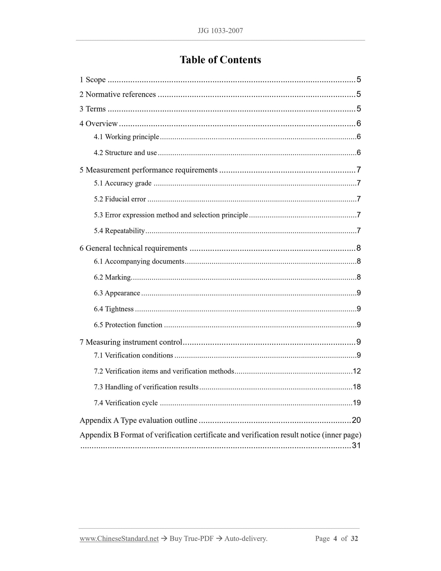
Table of Contents
1 Scope ... 5
2 Normative references ... 5
3 Terms ... 5
4 Overview ... 6
4.1 Working principle ... 6
4.2 Structure and use ... 6
5 Measurement performance requirements ... 7
5.1 Accuracy grade ... 7
5.2 Fiducial error ... 7
5.3 Error expression method and selection principle ... 7
5.4 Repeatability ... 7
6 General technical requirements ... 8
6.1 Accompanying documents ... 8
6.2 Marking... 8
6.3 Appearance ... 9
6.4 Tightness ... 9
6.5 Protection function ... 9
7 Measuring instrument control ... 9
7.1 Verification conditions ... 9
7.2 Verification items and verification methods ... 12
7.3 Handling of verification results ... 18
7.4 Verification cycle ... 19
Appendix A Type evaluation outline ... 20
Appendix B Format of verification certificate and verification result notice (inner page)
... 31
Verification regulation of electromagnetic flowmeters
1 Scope
This Regulation applies to the type evaluation, initial verification, subsequent
verification, in-use inspection of electromagnetic flowmeters (hereinafter referred to as
flowmeters), which are installed in closed pipelines. It is not applicable to flowmeters
for measuring blood, liquid metal, iron ore slurry and open channel flow measurement,
nor is it applicable to the verification of insertion electromagnetic flowmeters and
electromagnetic water meters.
2 Normative references
The provisions contained in the following standards and regulations constitute the
provisions of this Regulation through reference.
JJF 1004-2004 Metrological terms and their definitions for flow rate
GB/T 18659-2002 (idt ISO 9104:1991) Measurement of fluid flow in closed
conduits - Methods of evaluating the performance of electromagnetic flow - Meters
for liquids
GB/T 18660-2002 (idt ISO 6817:1992) Measurement of conductive liquid flow in
closed conduits - Method using electromagnetic flowmeters
JB/T 9248-1999 Electromagnetic flowmeters
It shall be noted that the current valid versions of the above references shall be used.
3 Terms
3.1 Primary device (sensor)
A device used to generate a signal proportional to the flow rate. The primary device
mainly includes the following units:
- A measuring tube through which the conductive liquid to be measured flows; its
inner surface is usually electrically insulated;
- One or more pairs of radially opposed electrodes, which are used to measure the
signal generated by the flow of the conductive liquid;
- An electromagnet that generates a magnetic field in the measuring tube.
3.2 Secondary device (converter)
A circuit device, that converts the induced electromotive force taken from the
primary device into a standard output signal proportional to the flow rate.
3.3 Meter characteristic coefficient
A parameter that can change the metering performance of the flowmeter by
modifying its value.
Note: 1. Due to different processes or names of flowmeters produced by different
manufacturers, this parameter may be a sensor coefficient, a converter coefficient, a
correction coefficient or other parameter;
2. This parameter may consist of one or a group of parameters.
3.4 Flow conditioner
A component that can reduce vortices and improve velocity distribution.
3.5 Fiducial error
The error of the flowmeter divided by the specific value of the flowmeter.
Note: This specific value is generally called the reference value, which can be the upper
limit of the flowmeter's range or nominal range.
4 Overview
4.1 Working principle
In a closed pipe, a magnetic field perpendicular to the flow direction is set up. The flow
rate is calculated by measuring the induced electromotive force generated by the
movement of the conductive liquid in the magnetic field.
4.2 Structure and use
The flow meter consists of a primary device and a secondary device. According to the
combination of the primary device and the secondary device, the flow meter can be
divided into a split type and an integrated type. The flow meter is mainly used to
measure the volume flow of conductive liquids.
7.1.1.2 The expanded uncertainty of the device measurement result shall not be greater
than 1/3 of the absolute value of the maximum allowable error of the flow being tested.
7.1.1.3 When the vapor pressure of the verification liquid is higher than the atmospheric
pressure, the device shall be closed.
7.1.1.4 The electrical equipment used for verification shall be grounded.
7.1.1.5 The equipment used to collect the output signal of the meter being tested during
the verification shall match the collected signal and meet the verification requirements.
7.1.1.6 If the instantaneous flow of the meter being tested is calibrated, the flow stability
of the device shall meet the following requirements: For flow meters with an absolute
value of the maximum allowable error equal to or less than 0.5%, the flow stability of
the device shall be better than 0.2%; for flow meters with an absolute value of the
maximum allowable error greater than 0.5%, the flow stability of the device shall be
better than 0.5%.
7.1.2 Verification liquid
7.1.2.1 The verification liquid can generally be clean water without air, fibers, magnetic
particles and other visible particles. If other liquids are used, their type (including
commercial name), viscosity, density, conductivity shall be stated in the verification
certificate.
7.1.2.2 During the verification, the liquid shall always fill the test pipe and flow in a
single phase, stable and vortex-free manner.
7.1.2.3 The pressure of the verification liquid at any point in the pipeline system and
flowmeter shall be higher than its saturated vapor pressure. For easily vaporized
verification liquids, there shall be a certain back pressure downstream of the flowmeter.
The recommended back pressure is 1.25 times the saturated vapor pressure of the
verification liquid at the highest verification temperature.
7.1.2.4 The conductivity of the verification liquid shall be in the range of 5 mS/m (50
µS/cm) to 500 mS/m (5000 µS/cm), or determined separately according to the technical
indicators given by the flowmeter manufacturer.
7.1.2.5 The temperature range of the verification liquid shall be between 4 °C and 35 °C.
During each verification process at each flow point, the liquid temperature change shall
not exceed ±0.5 °C.
7.1.3 Verification environmental conditions
7.1.3.1 Atmospheric environmental conditions shall generally meet the following
requirements:
- Ambient temperature: 5 °C ~ 35 °C;
- Relative humidity: 15% ~ 85%;
- Atmospheric pressure: 86 kPa ~ 106 kPa.
7.1.3.2 The AC power supply voltage shall be (220 ± 22) V; the power supply frequency
shall be (50 ± 2.5) Hz. A suitable AC or DC power supply (such as a 24V DC power
supply) can also be used, according to the requirements of the flow meter.
7.1.3.3 The external magnetic field shall be small enough to have negligible effect on
the flow meter.
7.1.3.4 Mechanical vibration and noise shall be small enough to have negligible effect
on the flow meter.
7.1.4 Installation conditions
7.1.4.1 Length of straight pipe segment on the upstream and downstream sides of the
flowmeter
Determine the length of the straight pipe segment on the upstream and downstream
sides of the flowmeter, according to the requirements of the flowmeter instruction
manual.
If there is no provision in the instruction manual, the primary device of the flowmeter
shall be installed in a straight pipe segment at least 10 times the nominal diameter (10
DN) away from any upstream disturbance component and 5 DN away from any
downstream disturbance component.
When the upstream straight pipe segment is not long enough, a flow regulator can be
installed; after installation, the length of its straight pipe segment shall meet the
requirements of the flow regulator instruction manual.
7.1.4.2 Requirements for straight pipe segments on the upstream and downstream sides
of the flowmeter
The inner wall of the straight pipe segment on the upstream and downstream sides of
the flowmeter shall be clean, without obvious dents, scale, peeling.
In the absence of specific provisions by the manufacturer, the deviation BETWEEN the
inner diameter of the straight pipe segment on the upstream and downstream sides of
the flowmeter AND the flowmeter measuring pipe diameter shall be less than 3%.
7.1.4.3 During installation, the flow direction of the flowmeter mark shall be consistent
with the flow direction of the fluid.
7.1.4.4 There shall be no leakage at the connection between the flowmeter and the test
7.2.3 Tightness inspection
After installing the flowmeter on the device, pass the test liquid to the maximum test
pressure and check the tightness of the flowmeter, which shall comply with the
requirements of Article 6.4.
7.2.4 Verification of relative indication error (or fiducial error)
7.2.4.1 Pre-operation inspection
Connect, start up, preheat, check the flowmeter parameter settings and zero point
verification, according to the method specified in the flowmeter manual.
7.2.4.2 Allow the verification liquid to flow through the flowmeter. Allow the
flowmeter to be in normal operation. Wait for the liquid temperature, pressure, flow rate
to stabilize before formal verification.
7.2.4.3 Verification flow points
The flowmeter verification shall include the following flow points: qmax, qmin, 0.10qmax,
0.25qmax, 0.50qmax, 0.75qmax. When the verification point is less than qmin, the
verification point can be cancelled.
During the verification process, the deviation between the actual verification flow rate
and the set flow rate at each flow point shall not exceed ±5% or ±1%qmax.
7.2.4.4 Number of verifications
For flow meters using relative indication error, the number of repeated verifications for
each flow point, which has an accuracy level equal to or better than 0.2, shall not be
less than 6. The number of repeated verifications for each flow point, which has an
accuracy level lower than 0.2, shall not be less than 3.
For flow meters using fiducial error, the number of repeated verifications for each flow
point shall not be less than 3.
7.2.4.5 Verification procedure
(1) Adjust the flow rate to the specified flow rate value; wait for the flow rate,
temperature, pressure to stabilize;
(2) Record the initial indications of the standard instrument and the flow meter to be
tested (or reset to zero); start the standard instrument (or the recording function
of the standard instrument) and the flow meter to be tested (or the output
function of the flow meter to be tested) at the same time;
(3) After running for a period of time according to the device operation requirements,
turn off the standard instrument (or the recording function of the standard
Appendix A
Type evaluation outline
A.1 Scope
This outline applies to the type evaluation of electromagnetic flowmeters.
A.2 References
The provisions contained in the following standards and regulations constitute the
provisions of this Regulation by reference.
JJF 1015-2002 General norm for pattern evaluation and pattern approval of
measuring instruments
JJF 1016-2002 The rules for drafting program of pattern evaluation of measuring
instruments
GB/T 6587.4-1986 Vibration test for electronic measuring instruments
GB 4208-1993 Degrees of protection provided by enclosure (IP code)
GB/T 17626.2-2006 Electromagnetic compatibility (EMC) - Testing and
measurement techniques - Electrostatic discharge immunity test
GB/T 17626.4-1998 Electromagnetic compatibility - Testing and measurement
techniques - Electrical fast transient/burst immunity test
GB/T 17626.5-1999 Electromagnetic compatibility - Testing and measurement
techniques - Surge immunity test
GB/T 17626.8-2006 Electromagnetic compatibility (EMC) - Part 8: Testing and
measurement techniques - Power frequency magnetic field immunity test
GB/T 17626.11-1999 Electromagnetic compatibility - Testing and measurement
techniques - Voltage dips, short interruptions and voltage variations immunity tests
JB/T 9329-1999 Basic environmental conditions and testing methods for
instruments transportation and storage in the transportation
When using this outline, attention shall be paid to the current valid versions of the
above-mentioned references.
A.3 Technical data and test prototypes submitted by the applicant
A.3.1 According to the requirements of Chapter 5 of JJF 1015.
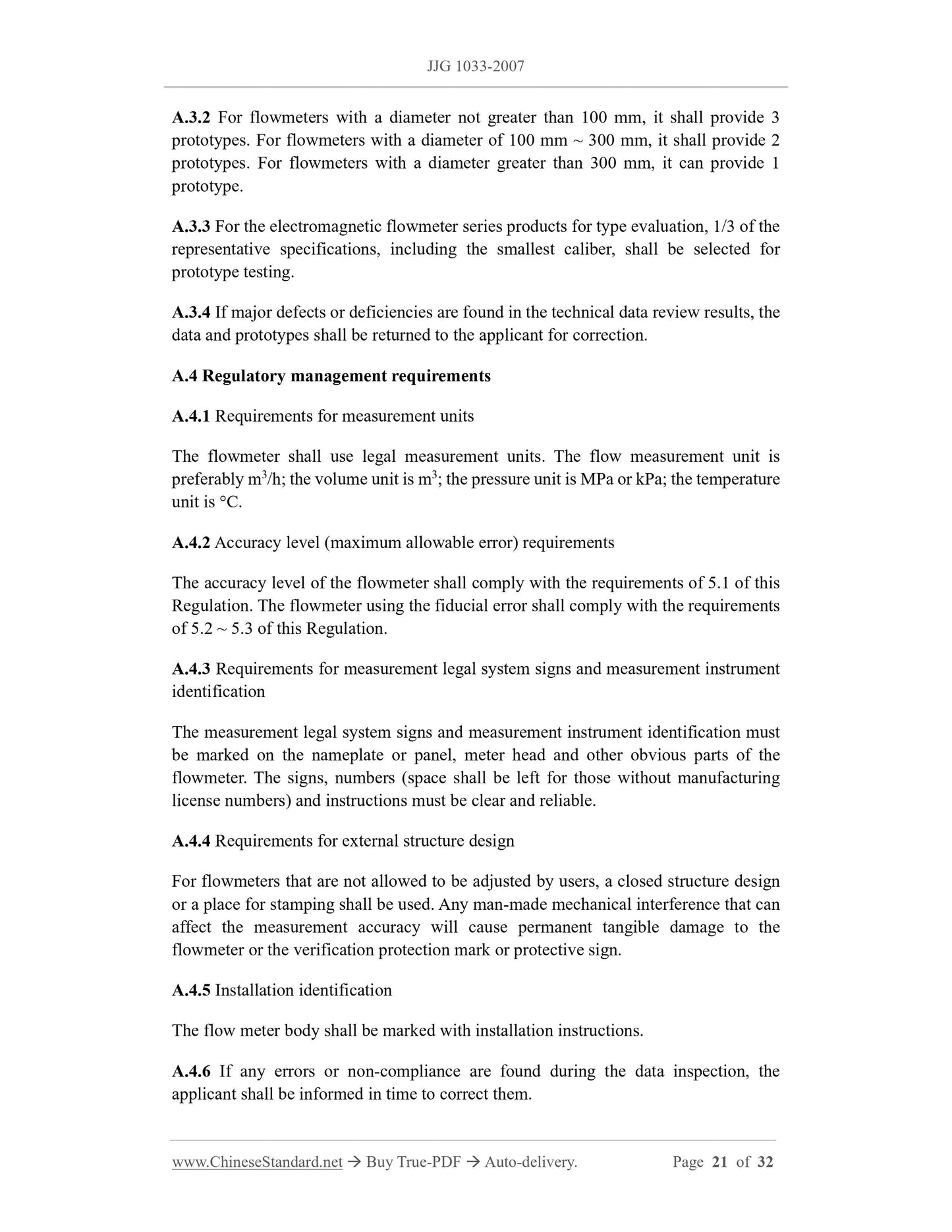
A.3.2 For flowmeters with a diameter not greater than 100 mm, it shall provide 3
prototypes. For flowmeters with a diameter of 100 mm ~ 300 mm, it shall provide 2
prototypes. For flowmeters with a diameter greater than 300 mm, it can provide 1
prototype.
A.3.3 For the electromagnetic flowmeter series products for type evaluation, 1/3 of the
representative specifications, including the smallest caliber, shall be selected for
prototype testing.
A.3.4 If major defects or deficiencies are found in the technical data review results, the
data and prototypes shall be returned to the applicant for correction.
A.4 Regulatory management requirements
A.4.1 Requirements for measurement units
The flowmeter shall use legal measurement units. The flow measurement unit is
preferably m3/h; the volume unit is m3; the pressure unit is MPa or kPa; the temperature
unit is °C.
A.4.2 Accuracy level (maximum allowable error) requirements
The accuracy level of the flowmeter shall comply with the requirements of 5.1 of this
Regulation. The flowmeter using the fiducial error shall comply with the requirements
of 5.2 ~ 5.3 of this Regulation.
A.4.3 Requirements for measurement legal system signs and measurement instrument
identification
Share
