1
/
of
11
PayPal, credit cards. Download editable-PDF and invoice in 1 second!
JJG 1038-2008 English PDF
JJG 1038-2008 English PDF
Regular price
$250.00 USD
Regular price
Sale price
$250.00 USD
Unit price
/
per
Shipping calculated at checkout.
Couldn't load pickup availability
Delivery: 3 seconds. Download true-PDF + Invoice.
Get QUOTATION in 1-minute: Click JJG 1038-2008
Historical versions: JJG 1038-2008
Preview True-PDF (Reload/Scroll if blank)
JJG 1038-2008: Verification Regulation of Goriolis Mass Flow Meters
JJG 1038-2008
JJG
NATIONAL METROLOGICAL VERIFICATION REGULATION
Goriolis Mass Flow Meters
ISSUED ON. MARCH 25, 2008
IMPLEMENTED ON. JUNE 25, 2008
Issued by. General Administration of Quality Supervision, Inspection and
Quarantine of the People's Republic of China
Table of Contents
1 Scope... 5
2 References... 5
3 Terms and definitions... 5
4 General... 6
4.1 Working principle... 6
4.2 Composition... 7
4.3 Purpose... 7
4.4 Output signal... 7
5 Measurement performance requirements... 7
5.1 Accuracy level... 7
5.2 Repeatability... 7
6 General technical requirements... 7
6.1 Accompanying documents... 7
6.2 Marking and nameplate... 8
6.3 Appearance... 8
6.4 Protection function... 8
6.5 Sealing property... 8
7 Control of measuring instruments... 8
7.1 Verification conditions... 8
7.2 Verification items and verification methods... 10
7.3 Processing of verification results... 14
7.4 Verification cycle... 15
Appendix A Outline of type evaluation... 16
Appendix B Verification certificate/verification result notice (inner page) format... 24
Verification Regulation of Goriolis Mass Flow Meters
1 Scope
This Regulation applies to the type evaluation, initial verification, subsequent
verification and in-use inspection of Coriolis mass flow meters (hereinafter referred to
as flow meters).
2 References
The provisions contained in the following standards and specifications constitute the
provisions of this Regulation through reference.
JJF 1094-2002, Evaluation of the Characteristics of Measuring Instruments
JJF 1004-2004, Metrological Terms and Their Definitions for Flow Rate
GB 17820-1999, Natural Gas
GB 50251-2003, Code for design of gas transmission pipeline engineering
GB/T 13609-1999, Natural gas - Sampling guidelines
GB/T 13610-2003, Analysis of natural gas by gas chromatography
GB/T 17747.2-1999, Natural gas - Calculation of compression factor - Part 2.
Calculation using molar-composition analysis
GB 3836.1-2000, Electrical apparatus for explosive gas atmospheres - Part 1.
General requirements
GB 3836.2-2000, Electrical apparatus for explosive gas atmospheres - Part 2.
Flameproof enclosure d
GB 3836.3-2000, Electrical apparatus for explosive gas atmospheres - Part 3.
Increased safety e
During the use of this Regulation, attention shall be paid to the currently valid version
of the above-referenced documents.
3 Terms and definitions
This Regulation uses the following terms and definitions, as well as the terms and
definitions specified in JJF 1094-2002 and JJF 1004-2004.
6.2 Marking and nameplate
6.2.1 The flow meter shall have clear flow direction markings.
6.2.2 The flow meter shall have a nameplate. The nameplate shall generally indicate the
name, model, factory number, measuring medium, flow range, nominal diameter,
accuracy level, maximum working pressure, power supply voltage, flow sensor material,
manufacturer and manufacturing date, manufacturing meter license mark and number,
explosion-proof level (for flammable and explosive occasions), and protection grade.
6.3 Appearance
6.3.1 Newly manufactured flow meters shall have good appearance, uniform surface
color, and shall be free of burrs, scratches, cracks, rust, mildew, peeling, etc. The sealing
surface shall be flat and free of damage.
6.3.2 The welding parts of the flow meter shall be smooth and clean, without any cold
welding or desoldering.
6.3.3 The connectors of the flow meter must be firm and reliable and must not become
loose or fall off due to vibration.
6.3.4 The numbers, words and symbols displayed on the flow meter shall be clear and
neat.
6.3.5 The buttons of the flow meter shall have a moderate feel and no sticking.
6.4 Protection function
The flow meter shall have protection functions (such as passwords, etc.) for the relevant
parameters that can change the metering performance of the flow meter. The meter
factor or pluses per unit shall be the same as the value in the previous verification
certificate.
6.5 Sealing property
Under the verification installation conditions, when the flow meter maintains the
maximum verification pressure for 5 minutes, there shall be no seepage or leakage at
all connections.
7 Control of measuring instruments
Measuring instrument control includes type evaluation, initial verification, subsequent
verification and in-use inspection. Appendix A is the outline of type evaluation.
7.1 Verification conditions
7.1.1 Requirements for flow standard devices
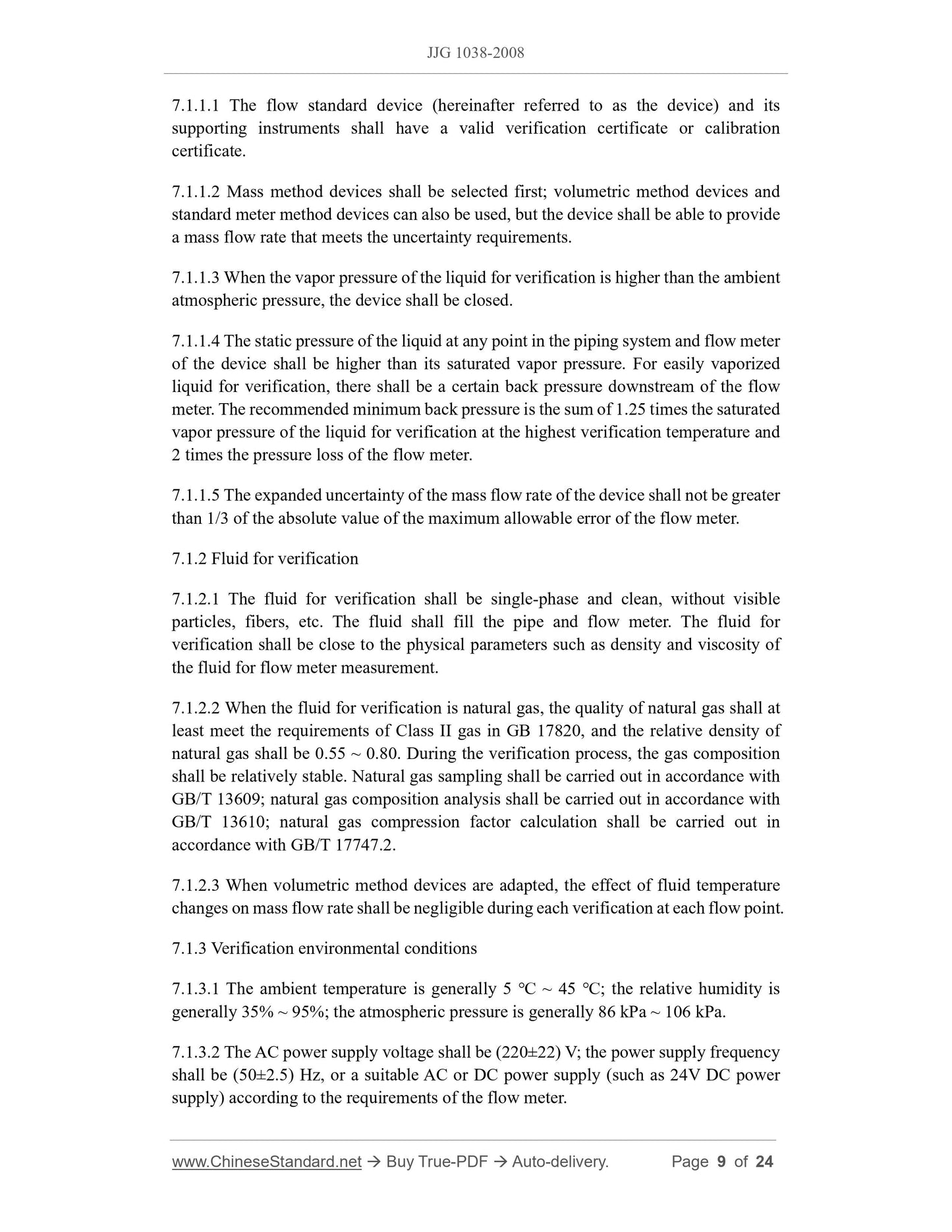
7.1.1.1 The flow standard device (hereinafter referred to as the device) and its
supporting instruments shall have a valid verification certificate or calibration
certificate.
7.1.1.2 Mass method devices shall be selected first; volumetric method devices and
standard meter method devices can also be used, but the device shall be able to provide
a mass flow rate that meets the uncertainty requirements.
7.1.1.3 When the vapor pressure of the liquid for verification is higher than the ambient
atmospheric pressure, the device shall be closed.
7.1.1.4 The static pressure of the liquid at any point in the piping system and flow meter
of the device shall be higher than its saturated vapor pressure. For easily vaporized
liquid for verification, there shall be a certain back pressure downstream of the flow
meter. The recommended minimum back pressure is the sum of 1.25 times the saturated
vapor pressure of the liquid for verification at the highest verification temperature and
2 times the pressure loss of the flow meter.
7.1.1.5 The expanded uncertainty of the mass flow rate of the device shall not be greater
than 1/3 of the absolute value of the maximum allowable error of the flow meter.
7.1.2 Fluid for verification
7.1.2.1 The fluid for verification shall be single-phase and clean, without visible
particles, fibers, etc. The fluid shall fill the pipe and flow meter. The fluid for
verification shall be close to the physical parameters such as density and viscosity of
the fluid for flow meter measurement.
7.1.2.2 When the fluid for verification is natural gas, the quality of natural gas shall at
least meet the requirements of Class II gas in GB 17820, and the relative density of
natural gas shall be 0.55 ~ 0.80.During the verification process, the gas composition
shall be relatively stable. Natural gas sampling shall be carried out in accordance with
GB/T 13609; natural gas composition analysis shall be carried out in accordance with
GB/T 13610; natural gas compression factor calculation shall be carried out in
accordance with GB/T 17747.2.
7.1.2.3 When volumetric method devices are adapted, the effect of fluid temperature
changes on mass flow rate shall be negligible during each verification at each flow point.
7.1.3 Verification environmental conditions
7.1.3.1 The ambient temperature is generally 5 ℃ ~ 45 ℃; the relative humidity is
generally 35% ~ 95%; the atmospheric pressure is generally 86 kPa ~ 106 kPa.
7.1.3.2 The AC power supply voltage shall be (220±22) V; the power supply frequency
shall be (50±2.5) Hz, or a suitable AC or DC power supply (such as 24V DC power
supply) according to the requirements of the flow meter.
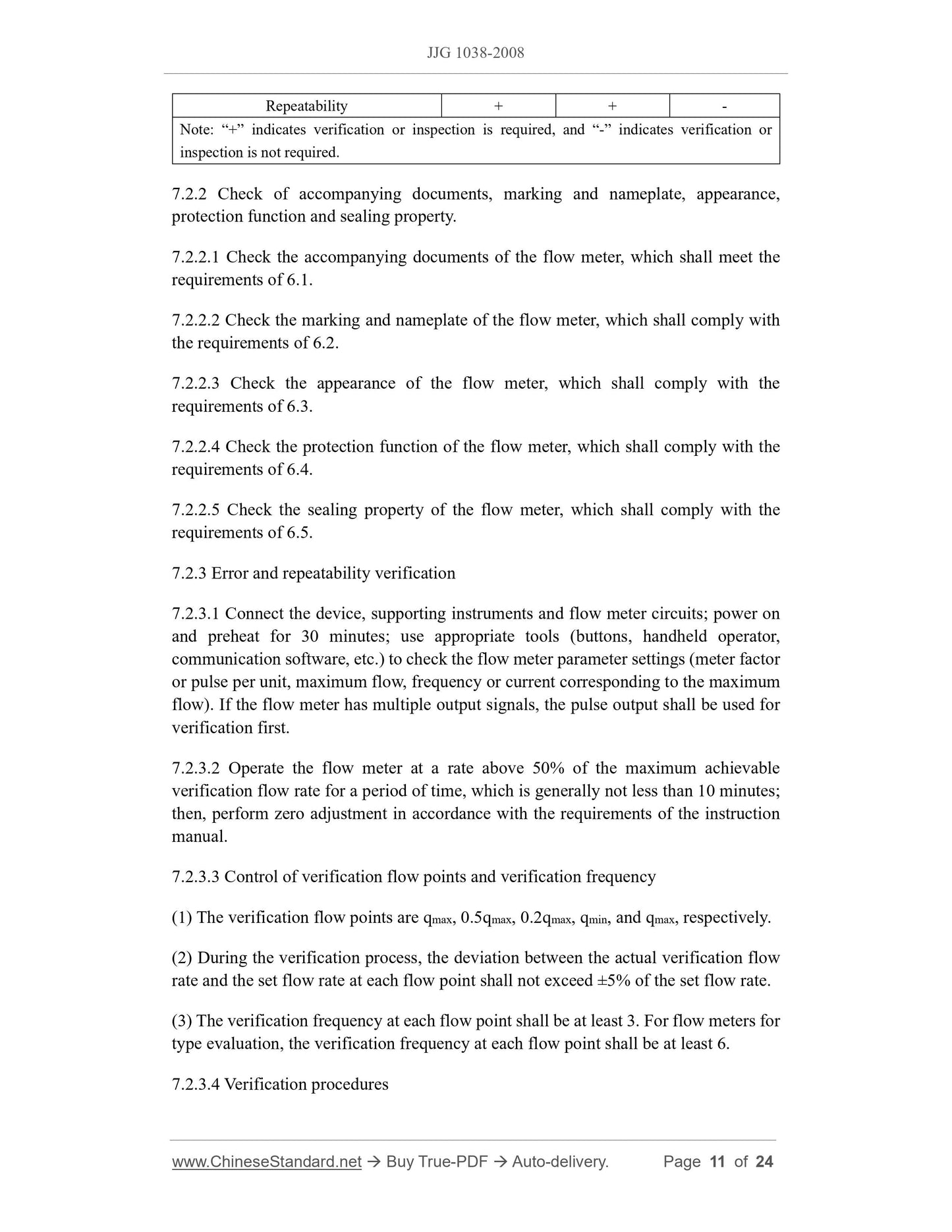
Repeatability + + -
Note. “+” indicates verification or inspection is required, and “-” indicates verification or
inspection is not required.
7.2.2 Check of accompanying documents, marking and nameplate, appearance,
protection function and sealing pro...
Get QUOTATION in 1-minute: Click JJG 1038-2008
Historical versions: JJG 1038-2008
Preview True-PDF (Reload/Scroll if blank)
JJG 1038-2008: Verification Regulation of Goriolis Mass Flow Meters
JJG 1038-2008
JJG
NATIONAL METROLOGICAL VERIFICATION REGULATION
Goriolis Mass Flow Meters
ISSUED ON. MARCH 25, 2008
IMPLEMENTED ON. JUNE 25, 2008
Issued by. General Administration of Quality Supervision, Inspection and
Quarantine of the People's Republic of China
Table of Contents
1 Scope... 5
2 References... 5
3 Terms and definitions... 5
4 General... 6
4.1 Working principle... 6
4.2 Composition... 7
4.3 Purpose... 7
4.4 Output signal... 7
5 Measurement performance requirements... 7
5.1 Accuracy level... 7
5.2 Repeatability... 7
6 General technical requirements... 7
6.1 Accompanying documents... 7
6.2 Marking and nameplate... 8
6.3 Appearance... 8
6.4 Protection function... 8
6.5 Sealing property... 8
7 Control of measuring instruments... 8
7.1 Verification conditions... 8
7.2 Verification items and verification methods... 10
7.3 Processing of verification results... 14
7.4 Verification cycle... 15
Appendix A Outline of type evaluation... 16
Appendix B Verification certificate/verification result notice (inner page) format... 24
Verification Regulation of Goriolis Mass Flow Meters
1 Scope
This Regulation applies to the type evaluation, initial verification, subsequent
verification and in-use inspection of Coriolis mass flow meters (hereinafter referred to
as flow meters).
2 References
The provisions contained in the following standards and specifications constitute the
provisions of this Regulation through reference.
JJF 1094-2002, Evaluation of the Characteristics of Measuring Instruments
JJF 1004-2004, Metrological Terms and Their Definitions for Flow Rate
GB 17820-1999, Natural Gas
GB 50251-2003, Code for design of gas transmission pipeline engineering
GB/T 13609-1999, Natural gas - Sampling guidelines
GB/T 13610-2003, Analysis of natural gas by gas chromatography
GB/T 17747.2-1999, Natural gas - Calculation of compression factor - Part 2.
Calculation using molar-composition analysis
GB 3836.1-2000, Electrical apparatus for explosive gas atmospheres - Part 1.
General requirements
GB 3836.2-2000, Electrical apparatus for explosive gas atmospheres - Part 2.
Flameproof enclosure d
GB 3836.3-2000, Electrical apparatus for explosive gas atmospheres - Part 3.
Increased safety e
During the use of this Regulation, attention shall be paid to the currently valid version
of the above-referenced documents.
3 Terms and definitions
This Regulation uses the following terms and definitions, as well as the terms and
definitions specified in JJF 1094-2002 and JJF 1004-2004.
6.2 Marking and nameplate
6.2.1 The flow meter shall have clear flow direction markings.
6.2.2 The flow meter shall have a nameplate. The nameplate shall generally indicate the
name, model, factory number, measuring medium, flow range, nominal diameter,
accuracy level, maximum working pressure, power supply voltage, flow sensor material,
manufacturer and manufacturing date, manufacturing meter license mark and number,
explosion-proof level (for flammable and explosive occasions), and protection grade.
6.3 Appearance
6.3.1 Newly manufactured flow meters shall have good appearance, uniform surface
color, and shall be free of burrs, scratches, cracks, rust, mildew, peeling, etc. The sealing
surface shall be flat and free of damage.
6.3.2 The welding parts of the flow meter shall be smooth and clean, without any cold
welding or desoldering.
6.3.3 The connectors of the flow meter must be firm and reliable and must not become
loose or fall off due to vibration.
6.3.4 The numbers, words and symbols displayed on the flow meter shall be clear and
neat.
6.3.5 The buttons of the flow meter shall have a moderate feel and no sticking.
6.4 Protection function
The flow meter shall have protection functions (such as passwords, etc.) for the relevant
parameters that can change the metering performance of the flow meter. The meter
factor or pluses per unit shall be the same as the value in the previous verification
certificate.
6.5 Sealing property
Under the verification installation conditions, when the flow meter maintains the
maximum verification pressure for 5 minutes, there shall be no seepage or leakage at
all connections.
7 Control of measuring instruments
Measuring instrument control includes type evaluation, initial verification, subsequent
verification and in-use inspection. Appendix A is the outline of type evaluation.
7.1 Verification conditions
7.1.1 Requirements for flow standard devices
7.1.1.1 The flow standard device (hereinafter referred to as the device) and its
supporting instruments shall have a valid verification certificate or calibration
certificate.
7.1.1.2 Mass method devices shall be selected first; volumetric method devices and
standard meter method devices can also be used, but the device shall be able to provide
a mass flow rate that meets the uncertainty requirements.
7.1.1.3 When the vapor pressure of the liquid for verification is higher than the ambient
atmospheric pressure, the device shall be closed.
7.1.1.4 The static pressure of the liquid at any point in the piping system and flow meter
of the device shall be higher than its saturated vapor pressure. For easily vaporized
liquid for verification, there shall be a certain back pressure downstream of the flow
meter. The recommended minimum back pressure is the sum of 1.25 times the saturated
vapor pressure of the liquid for verification at the highest verification temperature and
2 times the pressure loss of the flow meter.
7.1.1.5 The expanded uncertainty of the mass flow rate of the device shall not be greater
than 1/3 of the absolute value of the maximum allowable error of the flow meter.
7.1.2 Fluid for verification
7.1.2.1 The fluid for verification shall be single-phase and clean, without visible
particles, fibers, etc. The fluid shall fill the pipe and flow meter. The fluid for
verification shall be close to the physical parameters such as density and viscosity of
the fluid for flow meter measurement.
7.1.2.2 When the fluid for verification is natural gas, the quality of natural gas shall at
least meet the requirements of Class II gas in GB 17820, and the relative density of
natural gas shall be 0.55 ~ 0.80.During the verification process, the gas composition
shall be relatively stable. Natural gas sampling shall be carried out in accordance with
GB/T 13609; natural gas composition analysis shall be carried out in accordance with
GB/T 13610; natural gas compression factor calculation shall be carried out in
accordance with GB/T 17747.2.
7.1.2.3 When volumetric method devices are adapted, the effect of fluid temperature
changes on mass flow rate shall be negligible during each verification at each flow point.
7.1.3 Verification environmental conditions
7.1.3.1 The ambient temperature is generally 5 ℃ ~ 45 ℃; the relative humidity is
generally 35% ~ 95%; the atmospheric pressure is generally 86 kPa ~ 106 kPa.
7.1.3.2 The AC power supply voltage shall be (220±22) V; the power supply frequency
shall be (50±2.5) Hz, or a suitable AC or DC power supply (such as 24V DC power
supply) according to the requirements of the flow meter.
Repeatability + + -
Note. “+” indicates verification or inspection is required, and “-” indicates verification or
inspection is not required.
7.2.2 Check of accompanying documents, marking and nameplate, appearance,
protection function and sealing pro...
Share