1
/
of
8
PayPal, credit cards. Download editable-PDF and invoice in 1 second!
JJG 139-2014 English PDF
JJG 139-2014 English PDF
Regular price
$265.00 USD
Regular price
Sale price
$265.00 USD
Unit price
/
per
Shipping calculated at checkout.
Couldn't load pickup availability
Delivery: 3 seconds. Download true-PDF + Invoice.
Get QUOTATION in 1-minute: Click JJG 139-2014
Historical versions: JJG 139-2014
Preview True-PDF (Reload/Scroll if blank)
JJG 139-2014: Verification regulation of Tension, Compression and Universal Testing Machines
JJG 139-2014
JJG
NATIONAL METROLOGY VERIFICATION
REGULATION OF THE PEOPLE’S REPUBLIC OF CHINA
Tension, Compression and Universal Testing Machines
ISSUED ON: AUGUST 01, 2014
IMPLEMENTED ON: FEBRUARY 01, 2015
Issued by: General Administration of Quality Supervision, Inspection and
Quarantine
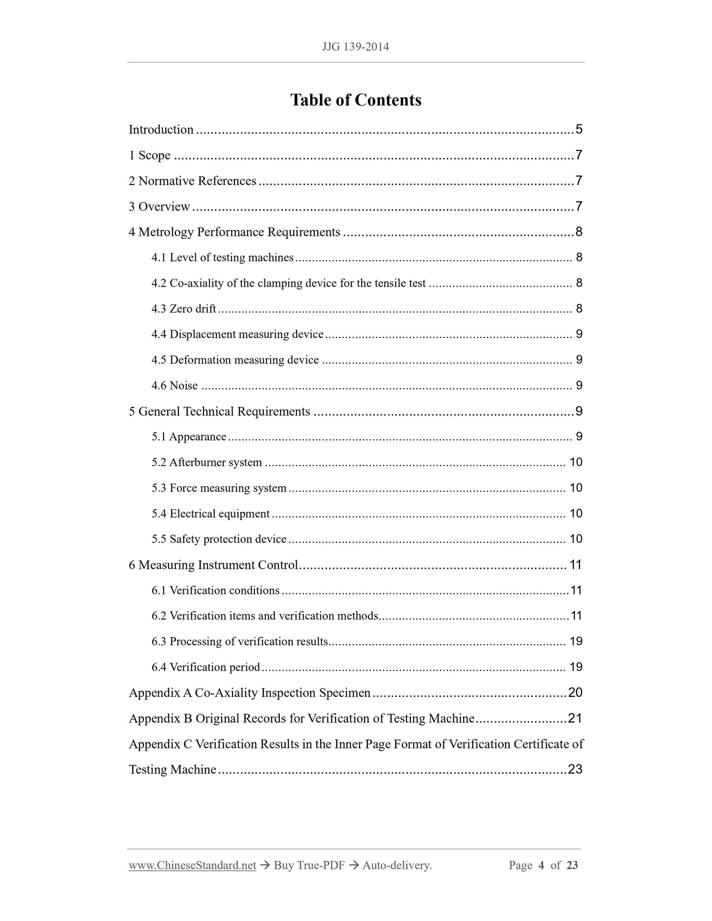
Table of Contents
Introduction ... 5
1 Scope ... 7
2 Normative References ... 7
3 Overview ... 7
4 Metrology Performance Requirements ... 8
4.1 Level of testing machines ... 8
4.2 Co-axiality of the clamping device for the tensile test ... 8
4.3 Zero drift ... 8
4.4 Displacement measuring device ... 9
4.5 Deformation measuring device ... 9
4.6 Noise ... 9
5 General Technical Requirements ... 9
5.1 Appearance ... 9
5.2 Afterburner system ... 10
5.3 Force measuring system ... 10
5.4 Electrical equipment ... 10
5.5 Safety protection device ... 10
6 Measuring Instrument Control ... 11
6.1 Verification conditions ... 11
6.2 Verification items and verification methods ... 11
6.3 Processing of verification results ... 19
6.4 Verification period ... 19
Appendix A Co-Axiality Inspection Specimen ... 20
Appendix B Original Records for Verification of Testing Machine ... 21
Appendix C Verification Results in the Inner Page Format of Verification Certificate of
Testing Machine ... 23
Verification Regulation of Tension, Compression and
Universal Testing Machines
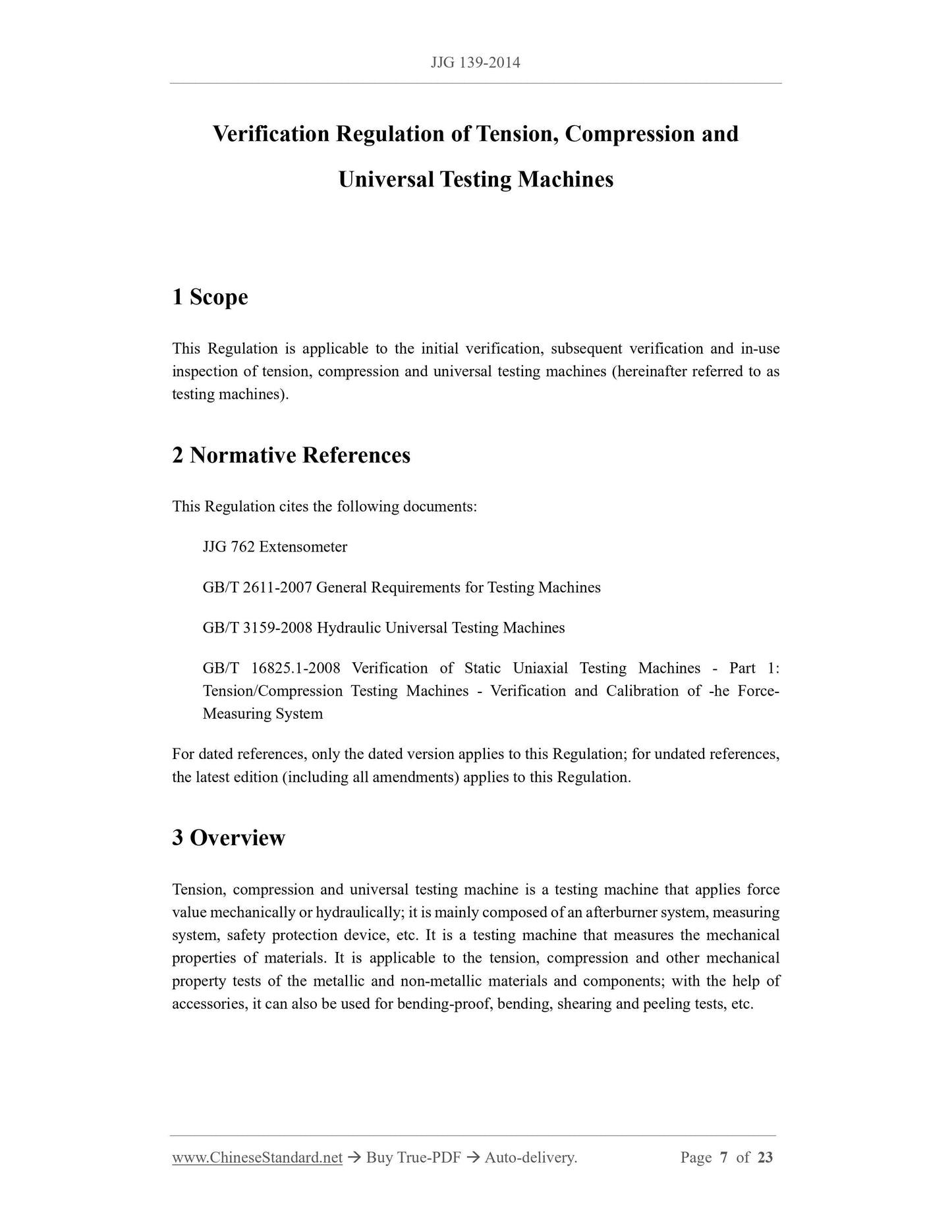
1 Scope
This Regulation is applicable to the initial verification, subsequent verification and in-use
inspection of tension, compression and universal testing machines (hereinafter referred to as
testing machines).
2 Normative References
This Regulation cites the following documents:
JJG 762 Extensometer
GB/T 2611-2007 General Requirements for Testing Machines
GB/T 3159-2008 Hydraulic Universal Testing Machines
GB/T 16825.1-2008 Verification of Static Uniaxial Testing Machines - Part 1:
Tension/Compression Testing Machines - Verification and Calibration of -he Force-
Measuring System
For dated references, only the dated version applies to this Regulation; for undated references,
the latest edition (including all amendments) applies to this Regulation.
3 Overview
Tension, compression and universal testing machine is a testing machine that applies force
value mechanically or hydraulically; it is mainly composed of an afterburner system, measuring
system, safety protection device, etc. It is a testing machine that measures the mechanical
properties of materials. It is applicable to the tension, compression and other mechanical
property tests of the metallic and non-metallic materials and components; with the help of
accessories, it can also be used for bending-proof, bending, shearing and peeling tests, etc.
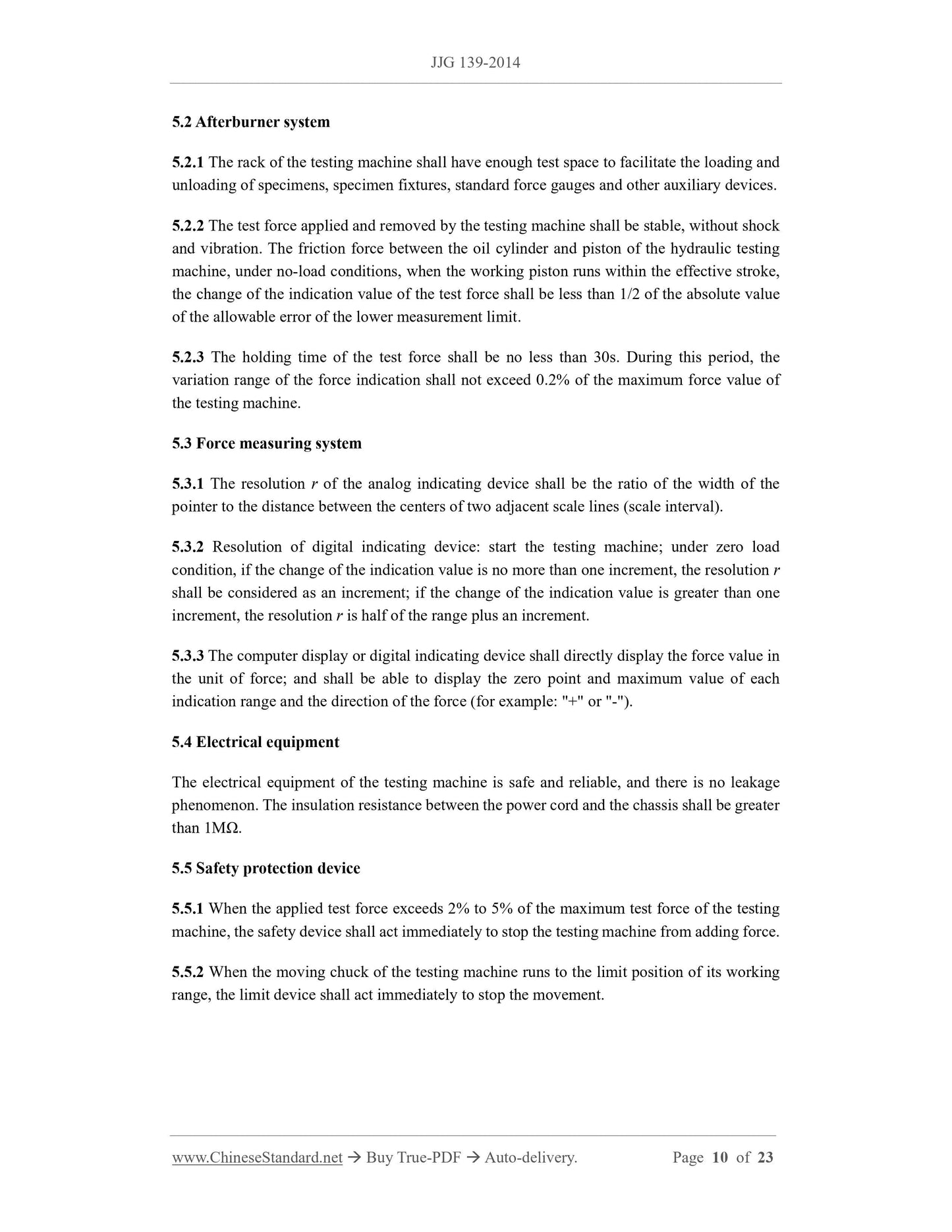
5.2 Afterburner system
5.2.1 The rack of the testing machine shall have enough test space to facilitate the loading and
unloading of specimens, specimen fixtures, standard force gauges and other auxiliary devices.
5.2.2 The test force applied and removed by the testing machine shall be stable, without shock
and vibration. The friction force between the oil cylinder and piston of the hydraulic testing
machine, under no-load conditions, when the working piston runs within the effective stroke,
the change of the indication value of the test force shall be less than 1/2 of the absolute value
of the allowable error of the lower measurement limit.
5.2.3 The holding time of the test force shall be no less than 30s. During this period, the
variation range of the force indication shall not exceed 0.2% of the maximum force value of
the testing machine.
5.3 Force measuring system
5.3.1 The resolution r of the analog indicating device shall be the ratio of the width of the
pointer to the distance between the centers of two adjacent scale lines (scale interval).
5.3.2 Resolution of digital indicating device: start the testing machine; under zero load
condition, if the change of the indication value is no more than one increment, the resolution r
shall be considered as an increment; if the change of the indication value is greater than one
increment, the resolution r is half of the range plus an increment.
5.3.3 The computer display or digital indicating device shall directly display the force value in
the unit of force; and shall be able to display the zero point and maximum value of each
indication range and the direction of the force (for example: "+" or "-").
5.4 Electrical equipment
The electrical equipment of the testing machine is safe and reliable, and there is no leakage
phenomenon. The insulation resistance between the power cord and the chassis shall be greater
than 1MΩ.
5.5 Safety protection device
5.5.1 When the applied test force exceeds 2% to 5% of the maximum test force of the testing
machine, the safety device shall act immediately to stop the testing machine from adding force.
5.5.2 When the moving chuck of the testing machine runs to the limit position of its working
range, the limit device shall act immediately to stop the movement.
corresponding accuracy) for verification. During verification, firstly clamp the test specimen
on the chuck and apply an initial force of about 1% of the maximum test force of the testing
machine; adjust the zero point of the co-axiality tester; and then apply the test force to 4% of
the maximum test force. Note that the maximum force used in the inspection shall not cause
plastic deformation of the inspection specimen; and measure the elastic deformation of the
opposite sides of the specimen, which shall be measured for three times each in the direction
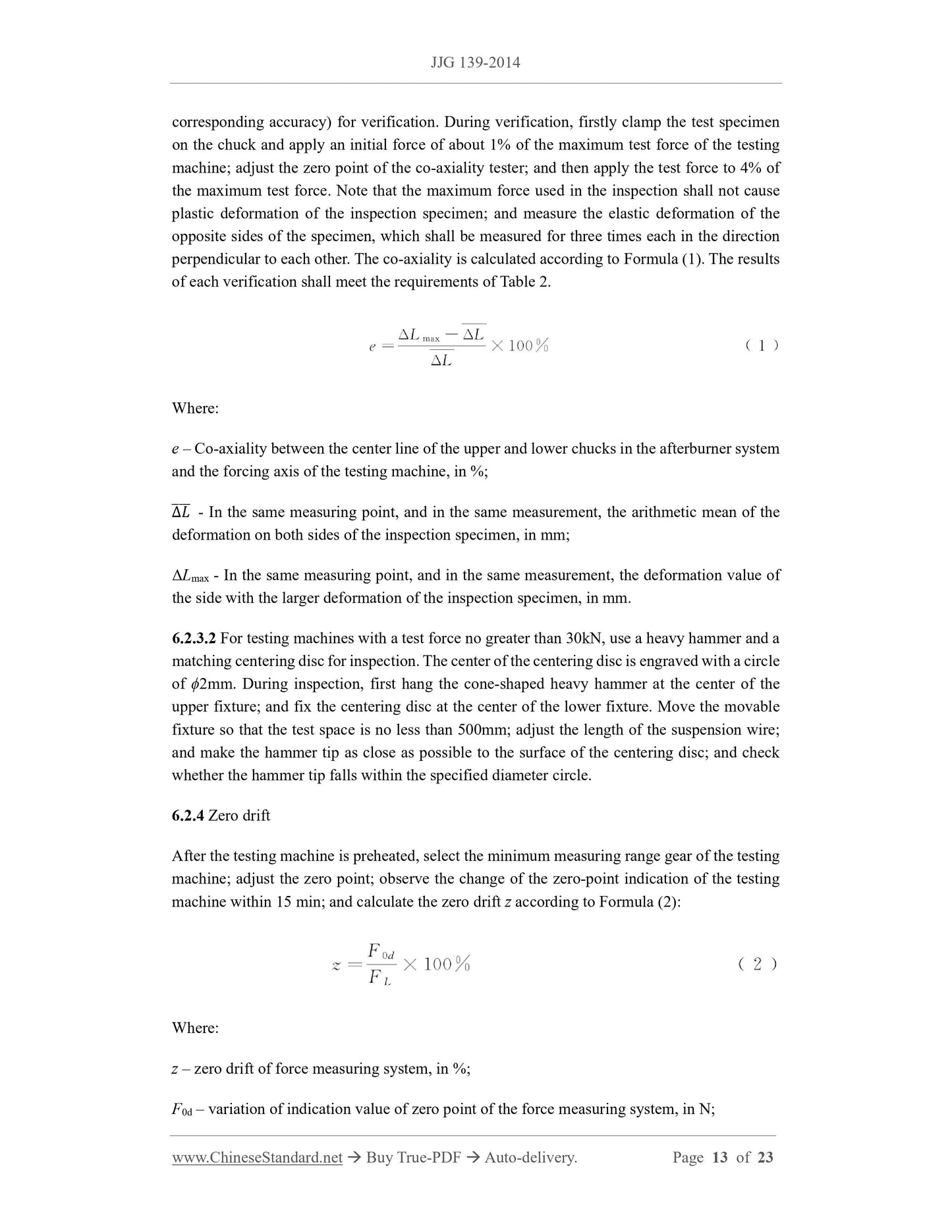
perpendicular to each other. The co-axiality is calculated according to Formula (1). The results
of each verification shall meet the requirements of Table 2.
Where:
e – Co-axiality between the center line of the upper and lower chucks in the afterburner system
and the forcing axis of the testing machine, in %;
Δ𝐿തതതത - In the same measuring point, and in the same measurement, the arithmetic mean of the
deformation on both sides of the inspection specimen, in mm;
ΔLmax - In the same measuring point, and in the same measurement, the deformation value of
the side with the larger deformation of the inspection specimen, in mm.
6.2.3.2 For testing machines with a test force no greater than 30kN, use a heavy hammer and a
matching centering disc for inspection. The center of the centering disc is engraved with a circle
of ϕ2mm. During inspection, first hang the cone-shaped heavy hammer at the center of the
upper fixture; and fix the centering disc at the center of the lower fixture. Move the movable
fixture so that the test space is no less than 500mm; adjust the length of the suspension wire;
and make the hammer tip as close as possible to the surface of the centering disc; and check
whether the hammer tip falls within the specified diameter circle.
6.2.4 Zero drift
After the testing machine is preheated, select the minimum measuring range gear of the testing
machine; adjust the zero point; observe the change of the zero-point indication of the testing
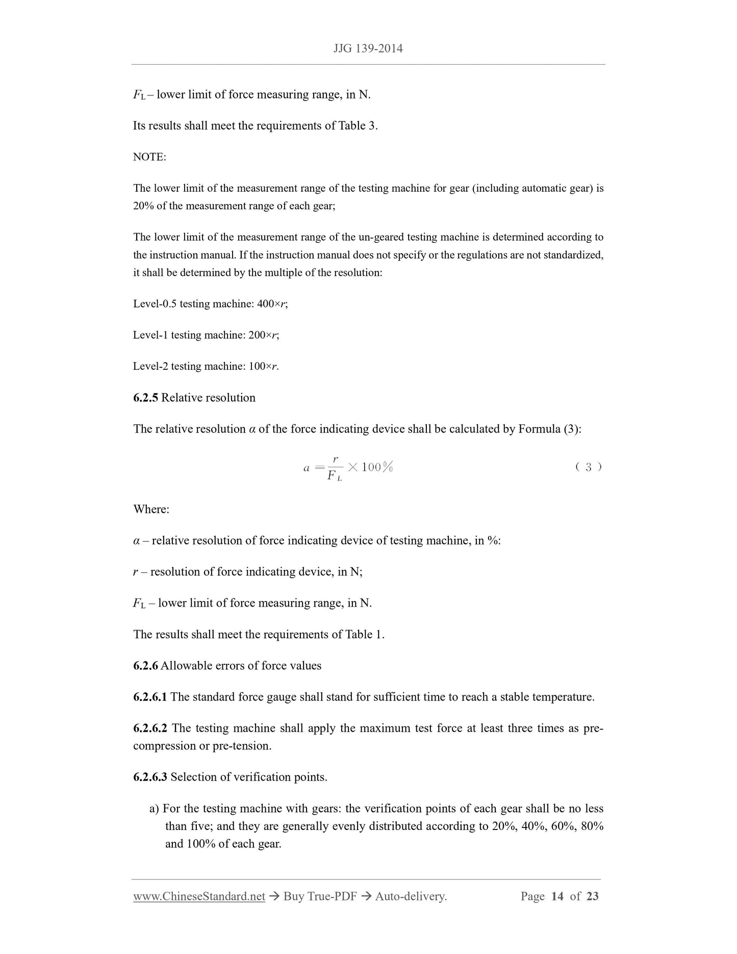
machine within 15 min; and calculate the zero drift z according to Formula (2):
Where:
z – zero drift of force measuring system, in %;
F0d – variation of indication value of zero point of the force measuring system, in N;
FL – lower limit of force measuring range, in N.
Its results shall meet the requirements of Table 3.
NOTE:
The lower limit of the measurement range of the testing machine for gea...
Get QUOTATION in 1-minute: Click JJG 139-2014
Historical versions: JJG 139-2014
Preview True-PDF (Reload/Scroll if blank)
JJG 139-2014: Verification regulation of Tension, Compression and Universal Testing Machines
JJG 139-2014
JJG
NATIONAL METROLOGY VERIFICATION
REGULATION OF THE PEOPLE’S REPUBLIC OF CHINA
Tension, Compression and Universal Testing Machines
ISSUED ON: AUGUST 01, 2014
IMPLEMENTED ON: FEBRUARY 01, 2015
Issued by: General Administration of Quality Supervision, Inspection and
Quarantine
Table of Contents
Introduction ... 5
1 Scope ... 7
2 Normative References ... 7
3 Overview ... 7
4 Metrology Performance Requirements ... 8
4.1 Level of testing machines ... 8
4.2 Co-axiality of the clamping device for the tensile test ... 8
4.3 Zero drift ... 8
4.4 Displacement measuring device ... 9
4.5 Deformation measuring device ... 9
4.6 Noise ... 9
5 General Technical Requirements ... 9
5.1 Appearance ... 9
5.2 Afterburner system ... 10
5.3 Force measuring system ... 10
5.4 Electrical equipment ... 10
5.5 Safety protection device ... 10
6 Measuring Instrument Control ... 11
6.1 Verification conditions ... 11
6.2 Verification items and verification methods ... 11
6.3 Processing of verification results ... 19
6.4 Verification period ... 19
Appendix A Co-Axiality Inspection Specimen ... 20
Appendix B Original Records for Verification of Testing Machine ... 21
Appendix C Verification Results in the Inner Page Format of Verification Certificate of
Testing Machine ... 23
Verification Regulation of Tension, Compression and
Universal Testing Machines
1 Scope
This Regulation is applicable to the initial verification, subsequent verification and in-use
inspection of tension, compression and universal testing machines (hereinafter referred to as
testing machines).
2 Normative References
This Regulation cites the following documents:
JJG 762 Extensometer
GB/T 2611-2007 General Requirements for Testing Machines
GB/T 3159-2008 Hydraulic Universal Testing Machines
GB/T 16825.1-2008 Verification of Static Uniaxial Testing Machines - Part 1:
Tension/Compression Testing Machines - Verification and Calibration of -he Force-
Measuring System
For dated references, only the dated version applies to this Regulation; for undated references,
the latest edition (including all amendments) applies to this Regulation.
3 Overview
Tension, compression and universal testing machine is a testing machine that applies force
value mechanically or hydraulically; it is mainly composed of an afterburner system, measuring
system, safety protection device, etc. It is a testing machine that measures the mechanical
properties of materials. It is applicable to the tension, compression and other mechanical
property tests of the metallic and non-metallic materials and components; with the help of
accessories, it can also be used for bending-proof, bending, shearing and peeling tests, etc.
5.2 Afterburner system
5.2.1 The rack of the testing machine shall have enough test space to facilitate the loading and
unloading of specimens, specimen fixtures, standard force gauges and other auxiliary devices.
5.2.2 The test force applied and removed by the testing machine shall be stable, without shock
and vibration. The friction force between the oil cylinder and piston of the hydraulic testing
machine, under no-load conditions, when the working piston runs within the effective stroke,
the change of the indication value of the test force shall be less than 1/2 of the absolute value
of the allowable error of the lower measurement limit.
5.2.3 The holding time of the test force shall be no less than 30s. During this period, the
variation range of the force indication shall not exceed 0.2% of the maximum force value of
the testing machine.
5.3 Force measuring system
5.3.1 The resolution r of the analog indicating device shall be the ratio of the width of the
pointer to the distance between the centers of two adjacent scale lines (scale interval).
5.3.2 Resolution of digital indicating device: start the testing machine; under zero load
condition, if the change of the indication value is no more than one increment, the resolution r
shall be considered as an increment; if the change of the indication value is greater than one
increment, the resolution r is half of the range plus an increment.
5.3.3 The computer display or digital indicating device shall directly display the force value in
the unit of force; and shall be able to display the zero point and maximum value of each
indication range and the direction of the force (for example: "+" or "-").
5.4 Electrical equipment
The electrical equipment of the testing machine is safe and reliable, and there is no leakage
phenomenon. The insulation resistance between the power cord and the chassis shall be greater
than 1MΩ.
5.5 Safety protection device
5.5.1 When the applied test force exceeds 2% to 5% of the maximum test force of the testing
machine, the safety device shall act immediately to stop the testing machine from adding force.
5.5.2 When the moving chuck of the testing machine runs to the limit position of its working
range, the limit device shall act immediately to stop the movement.
corresponding accuracy) for verification. During verification, firstly clamp the test specimen
on the chuck and apply an initial force of about 1% of the maximum test force of the testing
machine; adjust the zero point of the co-axiality tester; and then apply the test force to 4% of
the maximum test force. Note that the maximum force used in the inspection shall not cause
plastic deformation of the inspection specimen; and measure the elastic deformation of the
opposite sides of the specimen, which shall be measured for three times each in the direction
perpendicular to each other. The co-axiality is calculated according to Formula (1). The results
of each verification shall meet the requirements of Table 2.
Where:
e – Co-axiality between the center line of the upper and lower chucks in the afterburner system
and the forcing axis of the testing machine, in %;
Δ𝐿തതതത - In the same measuring point, and in the same measurement, the arithmetic mean of the
deformation on both sides of the inspection specimen, in mm;
ΔLmax - In the same measuring point, and in the same measurement, the deformation value of
the side with the larger deformation of the inspection specimen, in mm.
6.2.3.2 For testing machines with a test force no greater than 30kN, use a heavy hammer and a
matching centering disc for inspection. The center of the centering disc is engraved with a circle
of ϕ2mm. During inspection, first hang the cone-shaped heavy hammer at the center of the
upper fixture; and fix the centering disc at the center of the lower fixture. Move the movable
fixture so that the test space is no less than 500mm; adjust the length of the suspension wire;
and make the hammer tip as close as possible to the surface of the centering disc; and check
whether the hammer tip falls within the specified diameter circle.
6.2.4 Zero drift
After the testing machine is preheated, select the minimum measuring range gear of the testing
machine; adjust the zero point; observe the change of the zero-point indication of the testing
machine within 15 min; and calculate the zero drift z according to Formula (2):
Where:
z – zero drift of force measuring system, in %;
F0d – variation of indication value of zero point of the force measuring system, in N;
FL – lower limit of force measuring range, in N.
Its results shall meet the requirements of Table 3.
NOTE:
The lower limit of the measurement range of the testing machine for gea...
Share