1
/
of
6
PayPal, credit cards. Download editable-PDF and invoice in 1 second!
JJG 229-2010 English PDF
JJG 229-2010 English PDF
Regular price
$500.00 USD
Regular price
Sale price
$500.00 USD
Unit price
/
per
Shipping calculated at checkout.
Couldn't load pickup availability
Delivery: 3 seconds. Download true-PDF + Invoice.
Get QUOTATION in 1-minute: Click JJG 229-2010
Historical versions: JJG 229-2010
Preview True-PDF (Reload/Scroll if blank)
JJG 229-2010: Verification regulation of industry platinum and copper resistance thermometers
JJG 229-2010
JJG
NATIONAL METROLOGY VERIFICATION REGULATION
OF THE PEOPLE’S REPUBLIC OF CHINA
Industry Platinum and Copper Resistance
Thermometers
ISSUED ON: SEPTEMBER 06, 2010
IMPLEMENTED ON: MARCH 06, 2011
Issued by: General Administration of Quality Supervision, Inspection and
Quarantine
Table of Contents
1 Scope ... 5
2 References ... 5
3 Terms and Definitions ... 5
4 Overview ... 6
4.1 Composition ... 6
4.2 Temperature characteristics ... 6
5 Requirement for Metrology Performance ... 8
5.1 Tolerance ... 8
5.2 Stability ... 8
6 General Technical Requirements ... 9
6.1 Appearance ... 9
6.2 Insulation resistance ... 9
7 Control of Metrologic Instrument ... 10
7.1 Verification conditions ... 10
7.2 Verification items ... 12
7.3 Verification method ... 13
7.4 Processing of verification results ... 21
7.5 Verification period ... 22
Appendix A Allowable Range of Δα ... 23
Appendix B Temperature/Resistance Relationship Table ... 26
Appendix C Verification Record Format ... 31
Appendix D Format of Inner Page of Verification Certificate and Verification
Result Notice ... 33
Appendix E Uncertainty Evaluation of Measurement Results of Industrial
Platinum Thermal Resistance ... 34
Industry Platinum and Copper Resistance
Thermometers
1 Scope
This Regulation is applicable to the initial verification, subsequent verification and in-
use inspection of industry platinum thermal resistance in the whole or part temperature
range of -200°C~+850°C and with the nominal value α of temperature coefficient of
3.851×10⁻³°C-1; as well as the industry copper thermal resistance (hereinafter referred
to as thermal resistance) in the whole or part temperature range of -200°C~+850°C
and with the nominal value α of temperature coefficient of 4.280×10⁻³°C-1.
2 References
The following references are cited in this Regulation:
IEC 60751 (2008) Industrial Platinum Resistance Thermometers and Platinum
Temperature Sensors
JB/T 8623-1997 Technical Specification and Reference Table for Industrial Copper
Thermal Resistance
When citing, pay attention to using the currently valid version of the above cited
references.
3 Terms and Definitions
3.1 Resistance thermometer
A temperature measuring instrument composed of one or more temperature-sensing
resistance elements with lead wires, protective tubes and wiring terminals.
3.2 Nominal resistance R0
The expected resistance value of the thermal resistance (or temperature sensing
element) at 0°C. The resistance values are usually: 10Ω, 50Ω, 100Ω, 500Ω, 1000Ω,
which are declared by the manufacturer and marked on the thermal resistance.
Temperature sensing element is often characterized by its nominal resistance value.
For example, a Pt100 temperature sensing element has a nominal resistance value of
6 General Technical Requirements
6.1 Appearance
6.1.1 All parts of the thermal resistance shall be assembled correctly, reliably, and
without missing parts; the outer coating shall be firm; the protective tube shall be intact;
and there shall be no dents, scratches and significant corrosion;
6.1.2 The temperature sensing element must not be broken, and there must be no
obvious bending;
6.1.3 According to the needs of the measurement circuit, the thermal resistance can
have a two-, three- or four-wire connection mode; thereof, the Level-A and Level-AA
thermal resistance must be three-wire or four-wire connection.
6.1.4 Each thermal resistance shall have at least the following markings on its
protective sleeve or on its attached label:
● Type code;
● Nominal resistance value R0;
● Effective temperature range;
● Number of temperature sensing elements;
● Tolerance level;
● Manufacturer's name or trademark;
● Production year and month.
NOTE 1: If symbols are used to express such information, their markings shall be easy to
identify.
NOTE 2: The verification markings shall be placed on the protective sleeve or on the attached
label of the thermal resistance.
6.2 Insulation resistance
The insulation resistance between the temperature sensing element and the housing,
and each temperature sensing element shall meet the following requirements:
a) For the insulation resistance at room temperature, when the resistance
thermometer is in an environment with a temperature of 15°C ~35°C and a
relative humidity of 45%~85%, the insulation resistance shall be no less than
100MΩ;
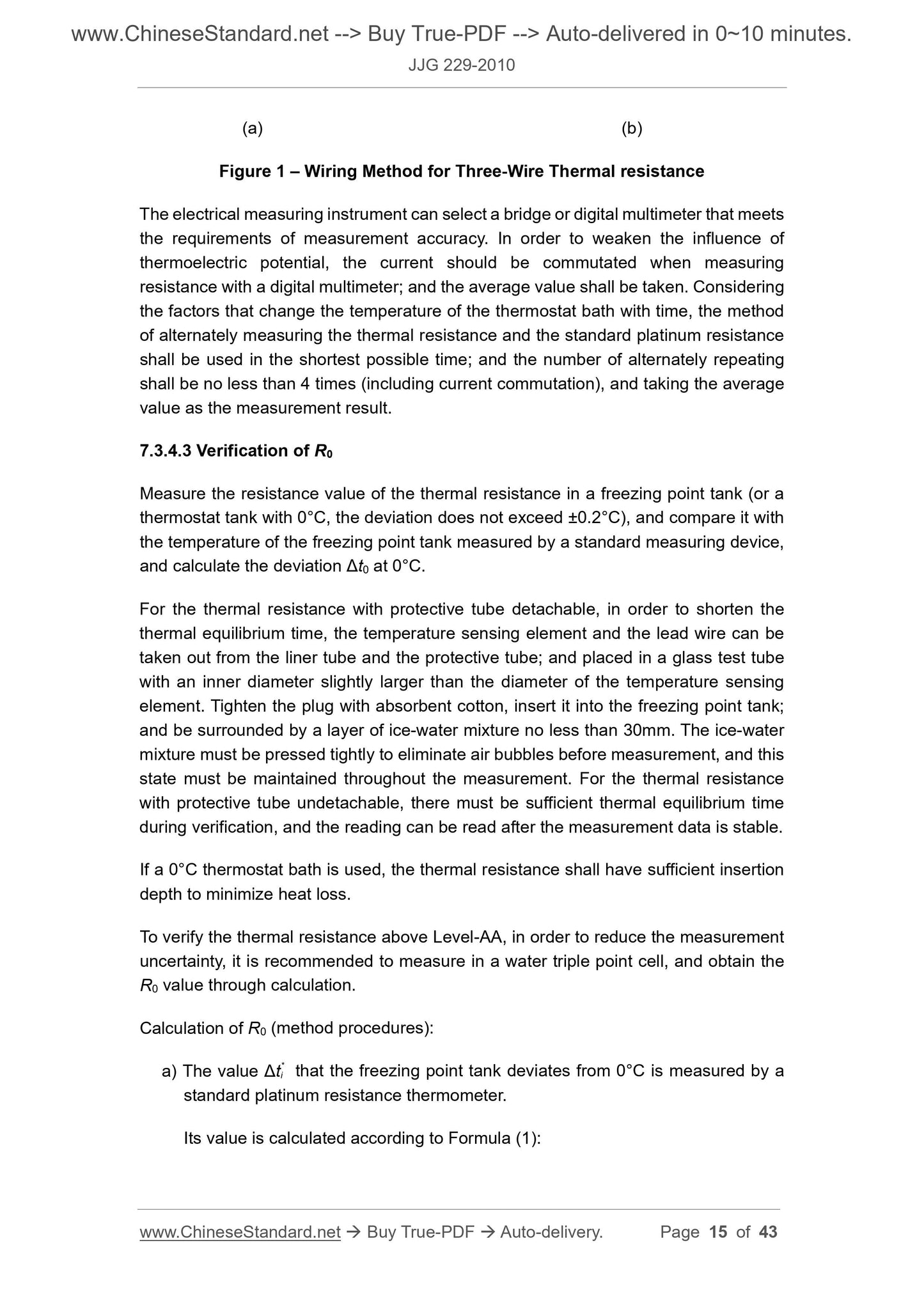
(a) (b)
Figure 1 – Wiring Method for Three-Wire Thermal resistance
The electrical measuring instrument can select a bridge or digital multimeter that meets
the requirements of measurement accuracy. In order to weaken the influence of
thermoelectric potential, the current should be commutated when measuring
resistance with a digital multimeter; and the average value shall be taken. Considering
the factors that change the temperature of the thermostat bath with time, the method
of alternately measuring the thermal resistance and the standard platinum resistance
shall be used in the shortest possible time; and the number of alternately repeating
shall be no less than 4 times (including current commutation), and taking the average
value as the measurement result.
7.3.4.3 Verification of R0
Measure the resistance value of the thermal resistance in a freezing point tank (or a
thermostat tank with 0°C, the deviation does not exceed ±0.2°C), and compare it with
the temperature of the freezing point tank measured by a standard measuring device,
and calculate the deviation Δt0 at 0°C.
For the thermal resistance with protective tube detachable, in order to shorten the
thermal equilibrium time, the temperature sensing element and the lead wire can be
taken out from the liner tube and the protective tube; and placed in a glass test tube
with an inner diameter slightly larger than the diameter of the temperature sensing
element. Tighten the plug with absorbent cotton, insert it into the freezing point tank;
and be surrounded by a layer of ice-water mixture no less than 30mm. The ice-water
mixture must be pressed tightly to eliminate air bubbles before measurement, and this
state must be maintained throughout the measurement. For the thermal resistance
with protective tube undetachable, there must be sufficient thermal equilibrium time
during verification, and the reading can be read after the measurement data is stable.
If a 0°C thermostat bath is used, the thermal resistance shall have sufficient insertion
depth to minimize heat loss.
To verify the thermal resistance above Level-AA, in order to reduce the measurement
uncertainty, it is recommended to measure in a water triple point cell, and obtain the
R0 value through calculation.
Calculation of R0 (method procedures):
a) The value Δt* i that the freezing point tank deviates from 0°C is measured by a
standard platinum resistance thermometer.
Its value is calculated according to Formula (1):
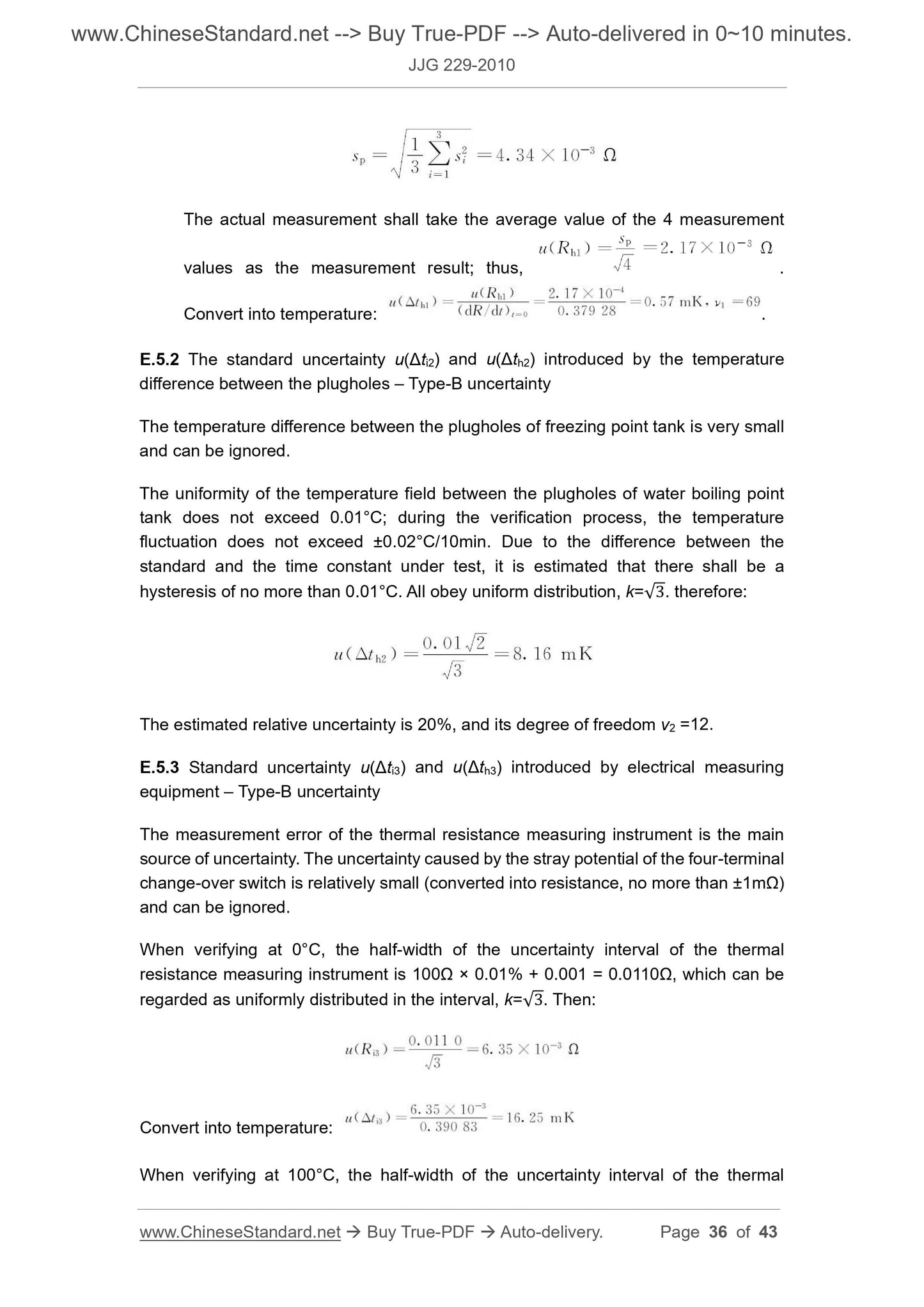
The actual measurement shall take the average value of the 4 measurement
values as the measurement result; thus, .
Convert into temperature: .
E.5.2 The standard uncertainty u(Δti2) and u(Δth2) introduced by the temperature
difference between the plugholes – Type-B uncertainty
The temperature difference between the plugholes of freezing point tank is very small
and can be ignored.
The uniformity of the temperature field between the plugholes of water boiling point
tank does not exceed 0.01°C; during th...
Get QUOTATION in 1-minute: Click JJG 229-2010
Historical versions: JJG 229-2010
Preview True-PDF (Reload/Scroll if blank)
JJG 229-2010: Verification regulation of industry platinum and copper resistance thermometers
JJG 229-2010
JJG
NATIONAL METROLOGY VERIFICATION REGULATION
OF THE PEOPLE’S REPUBLIC OF CHINA
Industry Platinum and Copper Resistance
Thermometers
ISSUED ON: SEPTEMBER 06, 2010
IMPLEMENTED ON: MARCH 06, 2011
Issued by: General Administration of Quality Supervision, Inspection and
Quarantine
Table of Contents
1 Scope ... 5
2 References ... 5
3 Terms and Definitions ... 5
4 Overview ... 6
4.1 Composition ... 6
4.2 Temperature characteristics ... 6
5 Requirement for Metrology Performance ... 8
5.1 Tolerance ... 8
5.2 Stability ... 8
6 General Technical Requirements ... 9
6.1 Appearance ... 9
6.2 Insulation resistance ... 9
7 Control of Metrologic Instrument ... 10
7.1 Verification conditions ... 10
7.2 Verification items ... 12
7.3 Verification method ... 13
7.4 Processing of verification results ... 21
7.5 Verification period ... 22
Appendix A Allowable Range of Δα ... 23
Appendix B Temperature/Resistance Relationship Table ... 26
Appendix C Verification Record Format ... 31
Appendix D Format of Inner Page of Verification Certificate and Verification
Result Notice ... 33
Appendix E Uncertainty Evaluation of Measurement Results of Industrial
Platinum Thermal Resistance ... 34
Industry Platinum and Copper Resistance
Thermometers
1 Scope
This Regulation is applicable to the initial verification, subsequent verification and in-
use inspection of industry platinum thermal resistance in the whole or part temperature
range of -200°C~+850°C and with the nominal value α of temperature coefficient of
3.851×10⁻³°C-1; as well as the industry copper thermal resistance (hereinafter referred
to as thermal resistance) in the whole or part temperature range of -200°C~+850°C
and with the nominal value α of temperature coefficient of 4.280×10⁻³°C-1.
2 References
The following references are cited in this Regulation:
IEC 60751 (2008) Industrial Platinum Resistance Thermometers and Platinum
Temperature Sensors
JB/T 8623-1997 Technical Specification and Reference Table for Industrial Copper
Thermal Resistance
When citing, pay attention to using the currently valid version of the above cited
references.
3 Terms and Definitions
3.1 Resistance thermometer
A temperature measuring instrument composed of one or more temperature-sensing
resistance elements with lead wires, protective tubes and wiring terminals.
3.2 Nominal resistance R0
The expected resistance value of the thermal resistance (or temperature sensing
element) at 0°C. The resistance values are usually: 10Ω, 50Ω, 100Ω, 500Ω, 1000Ω,
which are declared by the manufacturer and marked on the thermal resistance.
Temperature sensing element is often characterized by its nominal resistance value.
For example, a Pt100 temperature sensing element has a nominal resistance value of
6 General Technical Requirements
6.1 Appearance
6.1.1 All parts of the thermal resistance shall be assembled correctly, reliably, and
without missing parts; the outer coating shall be firm; the protective tube shall be intact;
and there shall be no dents, scratches and significant corrosion;
6.1.2 The temperature sensing element must not be broken, and there must be no
obvious bending;
6.1.3 According to the needs of the measurement circuit, the thermal resistance can
have a two-, three- or four-wire connection mode; thereof, the Level-A and Level-AA
thermal resistance must be three-wire or four-wire connection.
6.1.4 Each thermal resistance shall have at least the following markings on its
protective sleeve or on its attached label:
● Type code;
● Nominal resistance value R0;
● Effective temperature range;
● Number of temperature sensing elements;
● Tolerance level;
● Manufacturer's name or trademark;
● Production year and month.
NOTE 1: If symbols are used to express such information, their markings shall be easy to
identify.
NOTE 2: The verification markings shall be placed on the protective sleeve or on the attached
label of the thermal resistance.
6.2 Insulation resistance
The insulation resistance between the temperature sensing element and the housing,
and each temperature sensing element shall meet the following requirements:
a) For the insulation resistance at room temperature, when the resistance
thermometer is in an environment with a temperature of 15°C ~35°C and a
relative humidity of 45%~85%, the insulation resistance shall be no less than
100MΩ;
(a) (b)
Figure 1 – Wiring Method for Three-Wire Thermal resistance
The electrical measuring instrument can select a bridge or digital multimeter that meets
the requirements of measurement accuracy. In order to weaken the influence of
thermoelectric potential, the current should be commutated when measuring
resistance with a digital multimeter; and the average value shall be taken. Considering
the factors that change the temperature of the thermostat bath with time, the method
of alternately measuring the thermal resistance and the standard platinum resistance
shall be used in the shortest possible time; and the number of alternately repeating
shall be no less than 4 times (including current commutation), and taking the average
value as the measurement result.
7.3.4.3 Verification of R0
Measure the resistance value of the thermal resistance in a freezing point tank (or a
thermostat tank with 0°C, the deviation does not exceed ±0.2°C), and compare it with
the temperature of the freezing point tank measured by a standard measuring device,
and calculate the deviation Δt0 at 0°C.
For the thermal resistance with protective tube detachable, in order to shorten the
thermal equilibrium time, the temperature sensing element and the lead wire can be
taken out from the liner tube and the protective tube; and placed in a glass test tube
with an inner diameter slightly larger than the diameter of the temperature sensing
element. Tighten the plug with absorbent cotton, insert it into the freezing point tank;
and be surrounded by a layer of ice-water mixture no less than 30mm. The ice-water
mixture must be pressed tightly to eliminate air bubbles before measurement, and this
state must be maintained throughout the measurement. For the thermal resistance
with protective tube undetachable, there must be sufficient thermal equilibrium time
during verification, and the reading can be read after the measurement data is stable.
If a 0°C thermostat bath is used, the thermal resistance shall have sufficient insertion
depth to minimize heat loss.
To verify the thermal resistance above Level-AA, in order to reduce the measurement
uncertainty, it is recommended to measure in a water triple point cell, and obtain the
R0 value through calculation.
Calculation of R0 (method procedures):
a) The value Δt* i that the freezing point tank deviates from 0°C is measured by a
standard platinum resistance thermometer.
Its value is calculated according to Formula (1):
The actual measurement shall take the average value of the 4 measurement
values as the measurement result; thus, .
Convert into temperature: .
E.5.2 The standard uncertainty u(Δti2) and u(Δth2) introduced by the temperature
difference between the plugholes – Type-B uncertainty
The temperature difference between the plugholes of freezing point tank is very small
and can be ignored.
The uniformity of the temperature field between the plugholes of water boiling point
tank does not exceed 0.01°C; during th...
Share