1
/
of
9
PayPal, credit cards. Download editable-PDF and invoice in 1 second!
JJG 245-2005 English PDF
JJG 245-2005 English PDF
Regular price
$620.00 USD
Regular price
Sale price
$620.00 USD
Unit price
/
per
Shipping calculated at checkout.
Couldn't load pickup availability
Delivery: 3 seconds. Download true-PDF + Invoice.
Get QUOTATION in 1-minute: Click JJG 245-2005
Historical versions: JJG 245-2005
Preview True-PDF (Reload/Scroll if blank)
JJG 245-2005: Verification Regulation of Illuminance Meter
JJG 245-2005
JJG
METROLOGICAL VERIFICATION REGULATION
OF THE PEOPLE’S REPUBLIC OF CHINA
Illuminance meter
光照度计
ISSUED ON: APRIL 28, 2005
IMPLEMENTED ON: OCTOBER 10, 2005
Issued by: General Administration of Quality Supervision, Inspection and
Quarantine of PRC.
Table of Contents
1 Scope ... 4
2 Normative references ... 4
3 Overview ... 4
4 Metering performance requirements ... 4
4.1 Relative indication error ... 4
4.2 V(λ) matching error ... 5
4.3 Cosine characteristic (directional response) error ... 5
4.4 Nonlinear error ... 5
4.5 Shift error ... 5
4.6 Fatigue error ... 6
4.7 Infrared response error ... 6
4.8 UV response error ... 6
4.9 Temperature coefficient ... 6
5 General technical requirements ... 7
5.1 Appearance ... 7
5.2 Identification ... 7
5.3 Instructions ... 7
6 Metering instrument control ... 7
6.1 Verification conditions ... 7
6.2 Verification items ... 8
6.3 Verification method ... 9
6.4 Processing of verification results ... 13
6.5 Verification cycle ... 14
Appendix A Recommended test methods for type identification and prototype testing
... 15
Appendix B Verification of illuminance meter using comparison method ... 20
Appendix C Example of uncertainty assessment ... 22
Appendix D The relationship between the two formulas of cosine characteristic error
... 28
Appendix E Format of the inner page of the illuminance meter's verification certificate
and verification result notification ... 30
Verification regulation of illuminance meter
1 Scope
This Regulation applies to the initial verification, subsequent verification, in-use
inspection of illuminance meters (hereinafter referred to as illuminance meters). The
requirements related to measurement performance in type identification and prototype
testing can be implemented with reference to Regulation.
2 Normative references
This Regulation cites the following documents:
"Illuminance Meter" OIML 1988 English version
"Performance Test Methods for Photometers and Luminometers" CIE 1987 English
version
JJF 1059-1999 "Evaluation and Expression of Uncertainty in Measurement"
When using this Regulation, attention shall be paid to using the currently valid versions
of the above cited documents.
3 Overview
An illuminance meter is a measuring instrument for measuring illuminance. It consists
of a photometric probe (including a cosine corrector, a V (λ) correction filter, a
photoelectric receiver) and a display (digital or pointer type). When the photoelectric
receiver receives the optical radiation passing through the cosine corrector and V(λ)
filter, the generated photoelectric signal is processed and the corresponding illumination
value is displayed on the display.
4 Metering performance requirements
4.1 Relative indication error
The relative indication error of the illuminance meter shall not exceed the requirements
of Table 1.
l - The distance from the filament plane of the standard lamp to the test surface of
the photometric probe, m.
During verification, the distance -- between the filament plane of the standard lamp and
the photometric probe must be at least 15 times greater than the maximum linear
dimension of the light-emitting surface or the test surface of the photometric probe (the
diagonal length or diameter of the filament plane and the test surface of the photometric
probe).
The standard illuminance meter shall calibrate at least five equally spaced points, within
the full range of each gear. The level 1 and level 2 illuminance meters shall calibrate at
least three equally spaced points. Each point shall be illuminated for 5 seconds and its
display value shall be read. Each instrument is required to be verified for two rounds.
The relative deviation of the two rounds of values: standard, level 1, level 2 illuminance
meters shall not exceed 0.6%, 1%, 1.5%, respectively. The average value of each point
is taken as the final result. The relative indication errors of illuminance meters at all
levels shall comply with the requirements of 4.1.
Relative indication error = [(Displayed value - standard value) / Standard value] × 100%
(2)
For level 1 and level 2 illuminance meters, the comparison method can also be used for
verification. See Appendix B for the method.
6.3.3 Cosine characteristic (directional response) error of illuminance meter
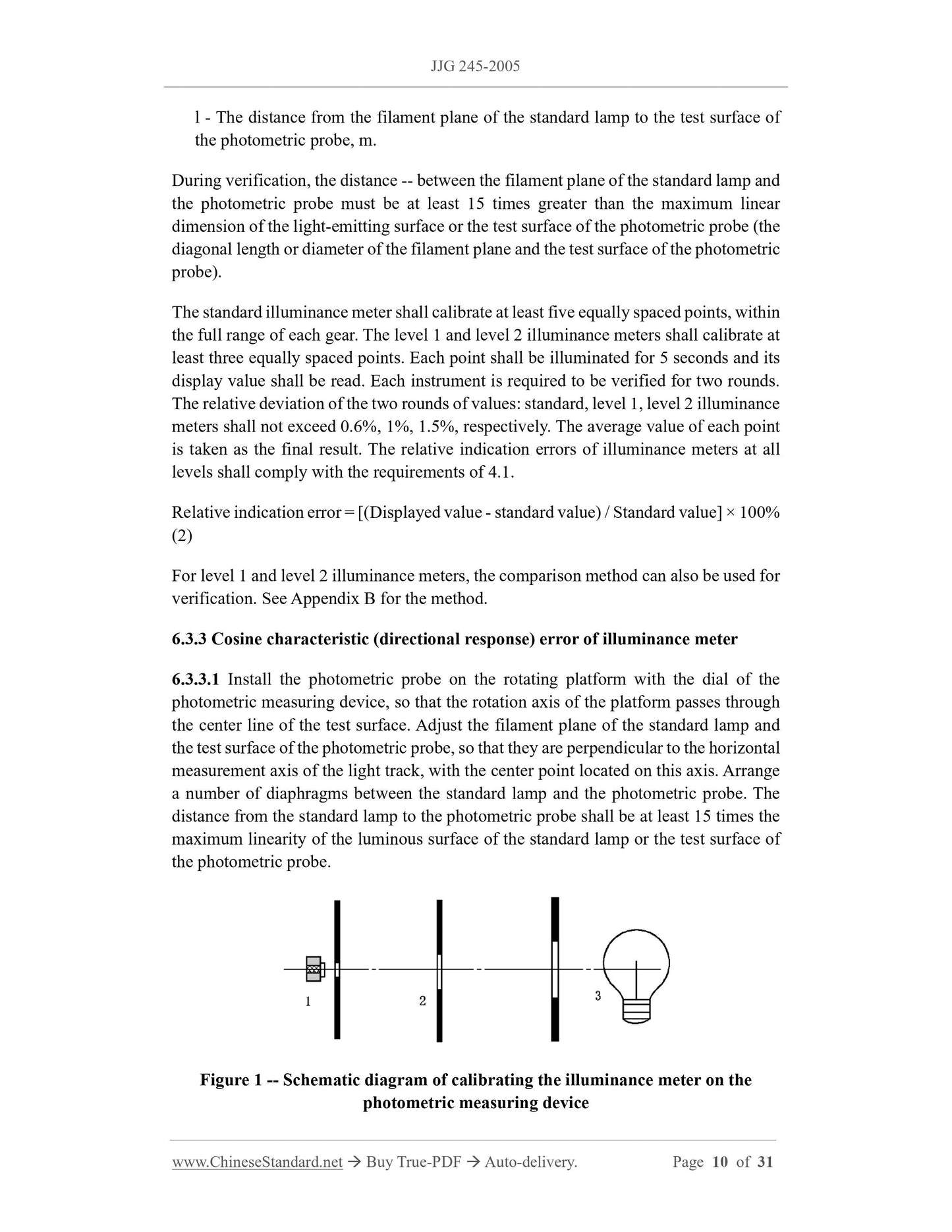
6.3.3.1 Install the photometric probe on the rotating platform with the dial of the
photometric measuring device, so that the rotation axis of the platform passes through
the center line of the test surface. Adjust the filament plane of the standard lamp and
the test surface of the photometric probe, so that they are perpendicular to the horizontal
measurement axis of the light track, with the center point located on this axis. Arrange
a number of diaphragms between the standard lamp and the photometric probe. The
distance from the standard lamp to the photometric probe shall be at least 15 times the
maximum linearity of the luminous surface of the standard lamp or the test surface of
the photometric probe.
Figure 1 -- Schematic diagram of calibrating the illuminance meter on the
photometric measuring device
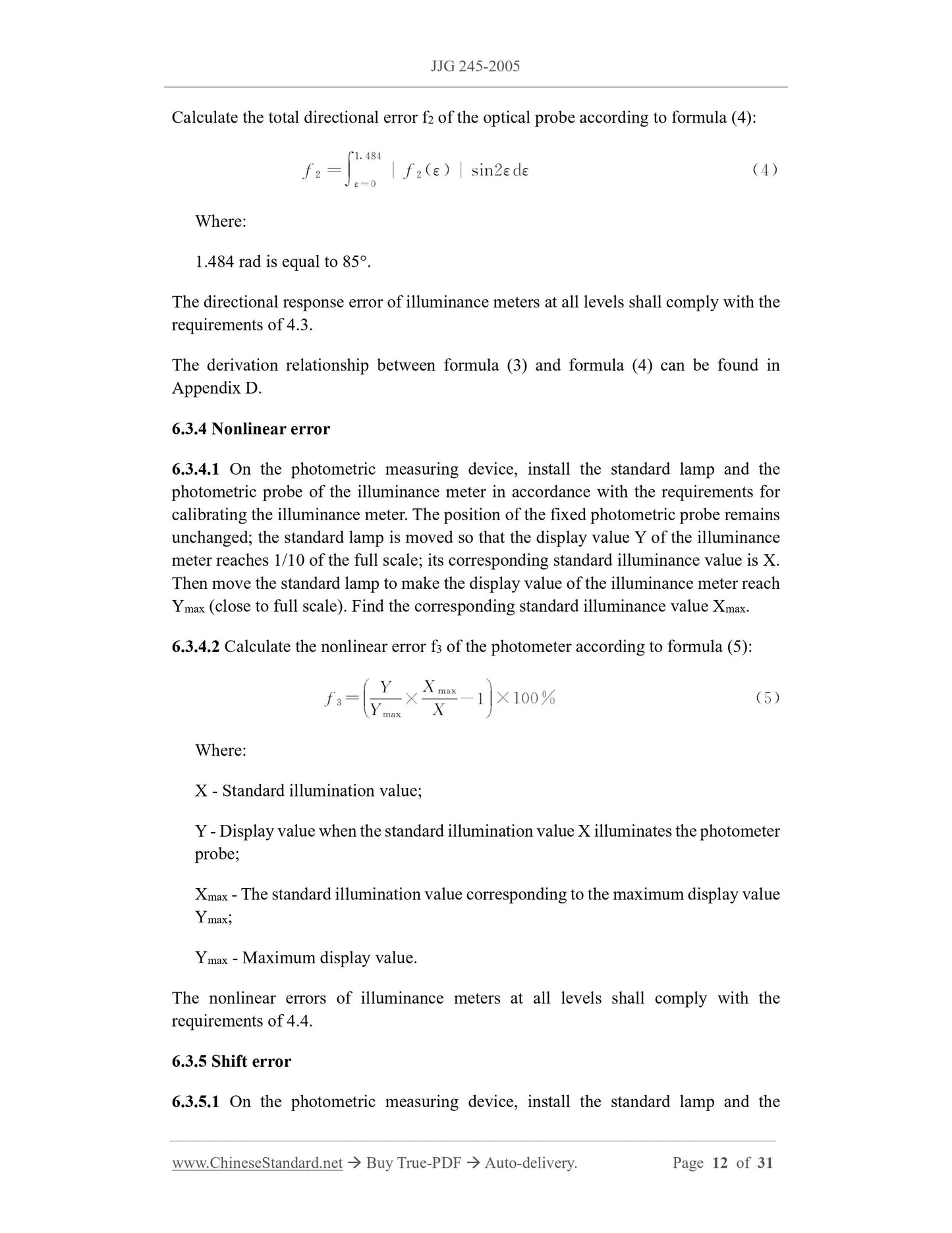
Calculate the total directional error f2 of the optical probe according to formula (4):
Where:
1.484 rad is equal to 85°.
The directional response error of illuminance meters at all levels shall comply with the
requirements of 4.3.
The derivation relationship between formula (3) and formula (4) can be found in
Appendix D.
6.3.4 Nonlinear error
6.3.4.1 On the photometric measuring device, install the standard lamp and the
photometric probe of the illuminance meter in accordance with the requirements for
calibrating the illuminance meter. The position of the fixed photometric probe remains
unchanged; the standard lamp is moved so that the display value Y of the illuminance
meter reaches 1/10 of the full scale; its corresponding standard illuminance value is X.
Then move the standard lamp to make the display value of the illuminance meter reach
Ymax (close to full scale). Find the corresponding standard illuminance value Xmax.
6.3.4.2 Calculate the nonlinear error f3 of the photometer according to formula (5):
Where:
X - Standard illumination value;
Y - Display value when the standard illumination value X illuminates the photometer
probe;
Xmax - The standard illumination value corresponding to the maximum display value
Ymax;
Ymax - Maximum display value.
The nonlinear errors of illuminance meters at all levels shall comply with the
requirements of 4.4.
6.3.5 Shift error
6.3.5.1 On the photometric measuring device, install the standard lamp and the
photometric probe of the illuminance meter in accordance with the requirements for
calibrating the illuminance meter. Keep the position of the fixed photometric probe
unchanged; move the standard lamp, so that the standard illumination value X (A)
reaches 90% of the full scale in the low-range gear A; its displayed value is Y (A). Then
change the illuminance meter to the relatively high range B; move the standard lamp so
that the standard illuminance value X (B) increases k times compared to X (A). Read
the illuminance meter's display value Y (B).
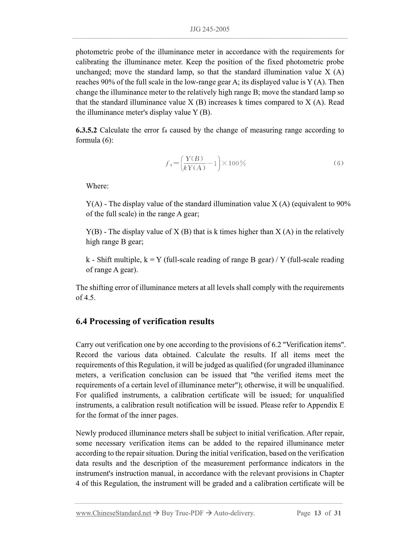
6.3.5.2 Calculate the error f4 caused by the change of measuring range according to
formula (6):
Where:
Y(A) - The display value of the standard illumination value X (A) (equivalent to 90%
of th...
Get QUOTATION in 1-minute: Click JJG 245-2005
Historical versions: JJG 245-2005
Preview True-PDF (Reload/Scroll if blank)
JJG 245-2005: Verification Regulation of Illuminance Meter
JJG 245-2005
JJG
METROLOGICAL VERIFICATION REGULATION
OF THE PEOPLE’S REPUBLIC OF CHINA
Illuminance meter
光照度计
ISSUED ON: APRIL 28, 2005
IMPLEMENTED ON: OCTOBER 10, 2005
Issued by: General Administration of Quality Supervision, Inspection and
Quarantine of PRC.
Table of Contents
1 Scope ... 4
2 Normative references ... 4
3 Overview ... 4
4 Metering performance requirements ... 4
4.1 Relative indication error ... 4
4.2 V(λ) matching error ... 5
4.3 Cosine characteristic (directional response) error ... 5
4.4 Nonlinear error ... 5
4.5 Shift error ... 5
4.6 Fatigue error ... 6
4.7 Infrared response error ... 6
4.8 UV response error ... 6
4.9 Temperature coefficient ... 6
5 General technical requirements ... 7
5.1 Appearance ... 7
5.2 Identification ... 7
5.3 Instructions ... 7
6 Metering instrument control ... 7
6.1 Verification conditions ... 7
6.2 Verification items ... 8
6.3 Verification method ... 9
6.4 Processing of verification results ... 13
6.5 Verification cycle ... 14
Appendix A Recommended test methods for type identification and prototype testing
... 15
Appendix B Verification of illuminance meter using comparison method ... 20
Appendix C Example of uncertainty assessment ... 22
Appendix D The relationship between the two formulas of cosine characteristic error
... 28
Appendix E Format of the inner page of the illuminance meter's verification certificate
and verification result notification ... 30
Verification regulation of illuminance meter
1 Scope
This Regulation applies to the initial verification, subsequent verification, in-use
inspection of illuminance meters (hereinafter referred to as illuminance meters). The
requirements related to measurement performance in type identification and prototype
testing can be implemented with reference to Regulation.
2 Normative references
This Regulation cites the following documents:
"Illuminance Meter" OIML 1988 English version
"Performance Test Methods for Photometers and Luminometers" CIE 1987 English
version
JJF 1059-1999 "Evaluation and Expression of Uncertainty in Measurement"
When using this Regulation, attention shall be paid to using the currently valid versions
of the above cited documents.
3 Overview
An illuminance meter is a measuring instrument for measuring illuminance. It consists
of a photometric probe (including a cosine corrector, a V (λ) correction filter, a
photoelectric receiver) and a display (digital or pointer type). When the photoelectric
receiver receives the optical radiation passing through the cosine corrector and V(λ)
filter, the generated photoelectric signal is processed and the corresponding illumination
value is displayed on the display.
4 Metering performance requirements
4.1 Relative indication error
The relative indication error of the illuminance meter shall not exceed the requirements
of Table 1.
l - The distance from the filament plane of the standard lamp to the test surface of
the photometric probe, m.
During verification, the distance -- between the filament plane of the standard lamp and
the photometric probe must be at least 15 times greater than the maximum linear
dimension of the light-emitting surface or the test surface of the photometric probe (the
diagonal length or diameter of the filament plane and the test surface of the photometric
probe).
The standard illuminance meter shall calibrate at least five equally spaced points, within
the full range of each gear. The level 1 and level 2 illuminance meters shall calibrate at
least three equally spaced points. Each point shall be illuminated for 5 seconds and its
display value shall be read. Each instrument is required to be verified for two rounds.
The relative deviation of the two rounds of values: standard, level 1, level 2 illuminance
meters shall not exceed 0.6%, 1%, 1.5%, respectively. The average value of each point
is taken as the final result. The relative indication errors of illuminance meters at all
levels shall comply with the requirements of 4.1.
Relative indication error = [(Displayed value - standard value) / Standard value] × 100%
(2)
For level 1 and level 2 illuminance meters, the comparison method can also be used for
verification. See Appendix B for the method.
6.3.3 Cosine characteristic (directional response) error of illuminance meter
6.3.3.1 Install the photometric probe on the rotating platform with the dial of the
photometric measuring device, so that the rotation axis of the platform passes through
the center line of the test surface. Adjust the filament plane of the standard lamp and
the test surface of the photometric probe, so that they are perpendicular to the horizontal
measurement axis of the light track, with the center point located on this axis. Arrange
a number of diaphragms between the standard lamp and the photometric probe. The
distance from the standard lamp to the photometric probe shall be at least 15 times the
maximum linearity of the luminous surface of the standard lamp or the test surface of
the photometric probe.
Figure 1 -- Schematic diagram of calibrating the illuminance meter on the
photometric measuring device
Calculate the total directional error f2 of the optical probe according to formula (4):
Where:
1.484 rad is equal to 85°.
The directional response error of illuminance meters at all levels shall comply with the
requirements of 4.3.
The derivation relationship between formula (3) and formula (4) can be found in
Appendix D.
6.3.4 Nonlinear error
6.3.4.1 On the photometric measuring device, install the standard lamp and the
photometric probe of the illuminance meter in accordance with the requirements for
calibrating the illuminance meter. The position of the fixed photometric probe remains
unchanged; the standard lamp is moved so that the display value Y of the illuminance
meter reaches 1/10 of the full scale; its corresponding standard illuminance value is X.
Then move the standard lamp to make the display value of the illuminance meter reach
Ymax (close to full scale). Find the corresponding standard illuminance value Xmax.
6.3.4.2 Calculate the nonlinear error f3 of the photometer according to formula (5):
Where:
X - Standard illumination value;
Y - Display value when the standard illumination value X illuminates the photometer
probe;
Xmax - The standard illumination value corresponding to the maximum display value
Ymax;
Ymax - Maximum display value.
The nonlinear errors of illuminance meters at all levels shall comply with the
requirements of 4.4.
6.3.5 Shift error
6.3.5.1 On the photometric measuring device, install the standard lamp and the
photometric probe of the illuminance meter in accordance with the requirements for
calibrating the illuminance meter. Keep the position of the fixed photometric probe
unchanged; move the standard lamp, so that the standard illumination value X (A)
reaches 90% of the full scale in the low-range gear A; its displayed value is Y (A). Then
change the illuminance meter to the relatively high range B; move the standard lamp so
that the standard illuminance value X (B) increases k times compared to X (A). Read
the illuminance meter's display value Y (B).
6.3.5.2 Calculate the error f4 caused by the change of measuring range according to
formula (6):
Where:
Y(A) - The display value of the standard illumination value X (A) (equivalent to 90%
of th...
Share