1
/
of
6
PayPal, credit cards. Download editable-PDF and invoice in 1 second!
JJG 551-2003 English PDF
JJG 551-2003 English PDF
Regular price
$170.00 USD
Regular price
Sale price
$170.00 USD
Unit price
/
per
Shipping calculated at checkout.
Couldn't load pickup availability
Delivery: 3 seconds. Download true-PDF + Invoice.
Get QUOTATION in 1-minute: Click JJG 551-2003
Historical versions: JJG 551-2003
Preview True-PDF (Reload/Scroll if blank)
JJG 551-2003: Verification regulation of sulfur dioxide gas detectors
JJG 551-2003
JJG
NATIONAL METROLOGICAL VERIFICATION REGULATIONS
OF THE PEOPLE’S REPUBLIC OF CHINA
Sulfur Dioxide Gas Detectors
ISSUED ON: MARCH 05, 2003
IMPLEMENTED ON: SEPTEMBER 21, 2005
Issued by: General Administration of Quality Supervision, Inspection and
Quarantine of the People's Republic of China
Table of Contents
1 Scope ... 5
2 Overview ... 5
3 Metering performance requirements ... 5
3.1 Indication error ... 5
3.2 Repeatability ... 5
3.3 Response time ... 5
3.4 Zero drift ... 6
3.5 Stability ... 6
3.6 Alarm setting error ... 6
4 General technical requirements ... 6
4.1 Appearance ... 6
4.2 Insulation resistance... 6
4.3 Insulation strength ... 7
5 Measuring instrument control ... 7
5.1 Verification conditions ... 7
5.2 Verification items ... 8
5.3 Verification methods ... 8
5.4 Verification result processing... 11
5.5 Verification period ... 11
Annex A Record format for sulfur dioxide gas detector verification ... 12
Annex B Inner page format of verification certificate and verification result notice
... 14
Sulfur Dioxide Gas Detectors
1 Scope
This Standard applies to the initial verification, subsequent verification and in-
use verification of the sulfur dioxide gas detector in the air.
2 Overview
The sulfur dioxide gas detector (hereinafter referred to as the detector) is mainly
composed of a chemical principle sensor or a physical principle sensor plus
electronic components and a display part. The sensor converts the sulfur
dioxide gas in the environment into an electrical signal. Then it is processed by
electronic parts. Display as concentration value.
The detector is divided into diffusion type and pump suction type.
3 Metering performance requirements
3.1 Indication error
According to the different uses of the detector, it can be divided into two
categories, as shown in Table 1.
Table 1 -- Detector category and indication error
3.2 Repeatability
The relative standard deviation shall not be greater than 2%.
3.3 Response time
It is not more than 60s for the diffusion type detector, not more than 30s for the
pump suction type detector.
4.3 Insulation strength
For the detector that uses 220V alternating current, the phase of the power
supply and the insulation strength of the interconnection line to the ground shall
be able to withstand the test that the AC voltage is 1500V, 50Hz, lasts for 1min.
There shall be no breakdown and arcing.
5 Measuring instrument control
The control of measuring instruments includes initial verification, subsequent
verification and in-use inspection.
5.1 Verification conditions
5.1.1 Verification of environmental conditions
5.1.1.1 Ambient temperature: (0~40)°C (fluctuation is less than ±5°C)
5.1.1.2 Relative humidity: ≤85%
5.1.1.3 Atmospheric pressure: (86~106)kPa
5.1.2 Verification equipment
5.1.2.1 Gas reference material
Use the sulfur dioxide standard gas provided by the unit with the corresponding
standard material "License for Manufacturing Measuring Instruments" approved
by the national measurement administration. Its expanded uncertainty is 2%
(k=3).
5.1.2.2 Zero calibration gas
Use high-purity nitrogen with a purity of 99.999%; or clean air with a sulfur
dioxide content of less than 1×10⁻⁶.
5.1.2.3 Flowmeter
0~1L/min; the accuracy level is not lower than level 3.
5.1.2.4 Stopwatch
Use electronic stopwatch or mechanical stopwatch.
5.1.2.5 Insulation resistance meter (500V)
5.1.2.6 Insulation strength tester (greater than 2.5kV)
Under the specified environmental conditions, after the detector is warmed up
and stabilized, use zero-point calibration gas to calibrate the instrument zero
point. Access standard gas with a concentration of about 80% of the range.
Read the stable value. Remove the standard gas. Make the detector display
zero. Then access the standard gas of the above concentration. At the same
time, use a stopwatch to record the time from the moment the standard gas is
introduced to the time when the detector displays 90% of the first stable value,
which shall be the response time of the detector. Repeat the above steps 3
times. Take the arithmetic average value as the response time of the detector.
5.3.7 Zero drift and stability
Under the specified environmental conditions, after the detector is warmed up
and stabilized, use zero-point gas and standard gas whose concentration is
about 80% of the upper limit of the measurement range to calibrate the zero
point and upper limit of the instrument. Access zero-point standard gas. Adjust
the instrument zero potentiometer. Adjust the display value of the detector to
10% of the range (if the zero point of the detector is not adjustable, read the
value directly). After the detector stabilizes, record the value C01. Then access
the standard gas with a concentration of about 80% of the detector range. After
the detector stabilizes, record the reading Cs1. Remove the standard gas.
Access zero-point gas. Remove the zero-point gas after the detector returns to
zero. The detector runs continuously for 6h. Repeat the above steps once every
1h interval (discontinuous measuring instrument runs continuously for 1h;
determine once every 10min interval). Record the readings C0i and Csi
separately. Calculate the zero drift (Δ0i or Δ0ri) according to formulas (4) and (5):
Where,
Δ0i - Zero drift of the detector (absolute value);
Δ0ri - Zero drift of the detector (relative value);
C0i - The ith zero drift reading of the detector;
C01 - The first zero drift reading of the detector.
Take the largest absolute value Δ0i or Δ0ri as the zero drift value of the detector.
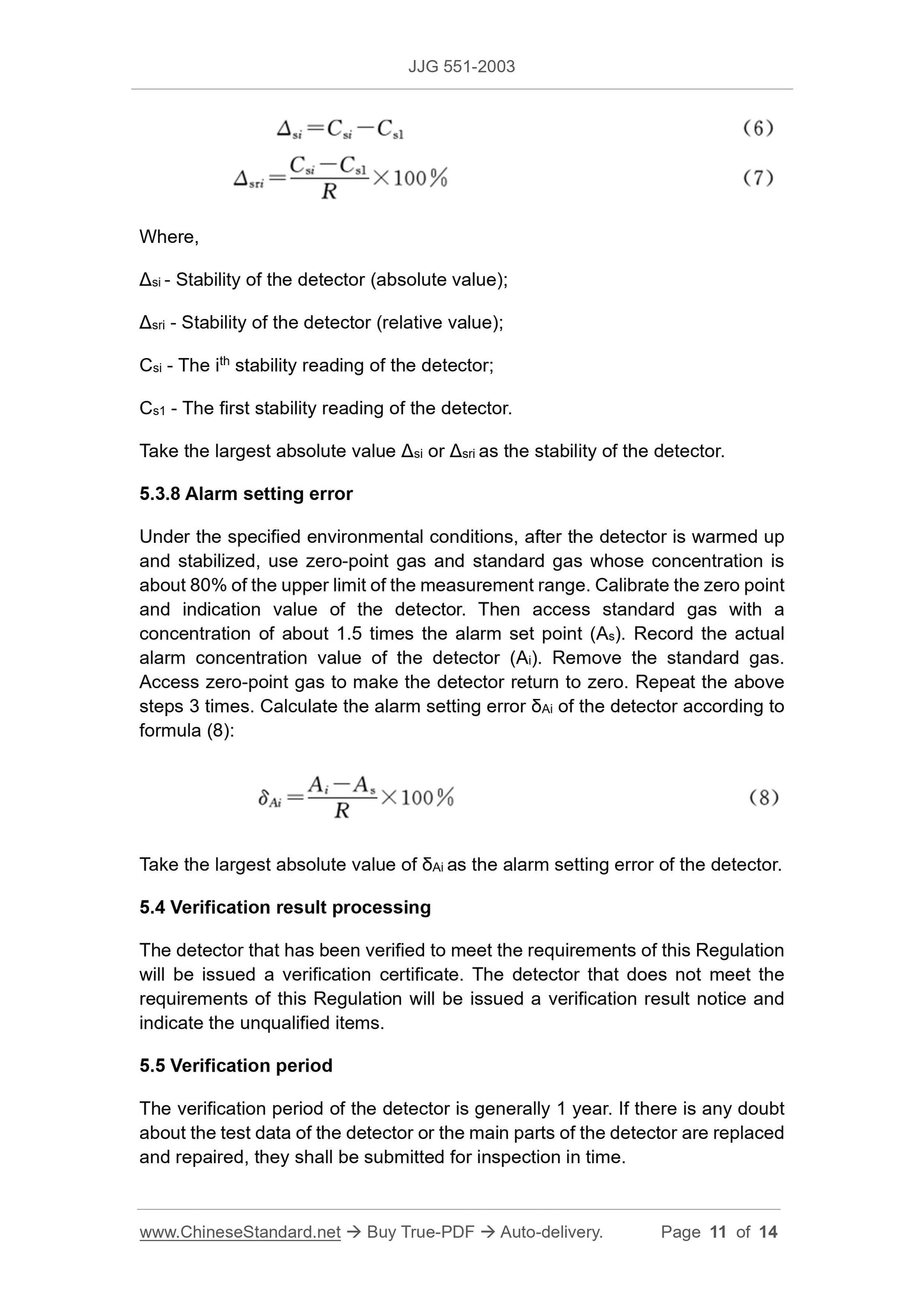
Calculate the stability (Δsi or Δsri) according to formulas (6) and (7):
Where,
Δsi - Stability of the detector (absolute value);
Δsri - Stability of the detector (relative value);
Csi - The ith stability reading of the detector;
Cs1 - The first stability reading of the detector.
Take the largest absolute value Δsi or Δsri as the stability of the detector.
5.3.8 Alarm setting error
Under the specified environmental conditions, after the detector is warmed up
and stabilized, use zero-point gas and standard gas whose concentration is
about 80% of the upper limit of the measurement range. Calibrate the zero point
and indication value of the detector. Then access standard gas with a
concentration of about 1.5 times the alarm set point (As). Record the actual
alarm concentration value of the detector (Ai). Remove the standard gas.
Access zero-point gas to make the detector return to zero. Repeat the above
steps 3 times. Calculate the alarm setting error δAi of the detector according to
formula (8):
Take the largest absolute value of δAi as the alarm setting error of the detector.
5.4 Verification result processing
The detector that has been verified to meet the requirements of this Regulation
will be issued a verification certificate. The detector that does not meet the
requirements of this Regulation will be issued a verification result notice and
indicate the unqualified items.
5.5 Verification period
The verification period of the detector is generally 1 year. If there is any doubt
about the test data of the detector or the main parts of the detector are replaced
and repaired, they shall be submitted for inspection in time.
Get QUOTATION in 1-minute: Click JJG 551-2003
Historical versions: JJG 551-2003
Preview True-PDF (Reload/Scroll if blank)
JJG 551-2003: Verification regulation of sulfur dioxide gas detectors
JJG 551-2003
JJG
NATIONAL METROLOGICAL VERIFICATION REGULATIONS
OF THE PEOPLE’S REPUBLIC OF CHINA
Sulfur Dioxide Gas Detectors
ISSUED ON: MARCH 05, 2003
IMPLEMENTED ON: SEPTEMBER 21, 2005
Issued by: General Administration of Quality Supervision, Inspection and
Quarantine of the People's Republic of China
Table of Contents
1 Scope ... 5
2 Overview ... 5
3 Metering performance requirements ... 5
3.1 Indication error ... 5
3.2 Repeatability ... 5
3.3 Response time ... 5
3.4 Zero drift ... 6
3.5 Stability ... 6
3.6 Alarm setting error ... 6
4 General technical requirements ... 6
4.1 Appearance ... 6
4.2 Insulation resistance... 6
4.3 Insulation strength ... 7
5 Measuring instrument control ... 7
5.1 Verification conditions ... 7
5.2 Verification items ... 8
5.3 Verification methods ... 8
5.4 Verification result processing... 11
5.5 Verification period ... 11
Annex A Record format for sulfur dioxide gas detector verification ... 12
Annex B Inner page format of verification certificate and verification result notice
... 14
Sulfur Dioxide Gas Detectors
1 Scope
This Standard applies to the initial verification, subsequent verification and in-
use verification of the sulfur dioxide gas detector in the air.
2 Overview
The sulfur dioxide gas detector (hereinafter referred to as the detector) is mainly
composed of a chemical principle sensor or a physical principle sensor plus
electronic components and a display part. The sensor converts the sulfur
dioxide gas in the environment into an electrical signal. Then it is processed by
electronic parts. Display as concentration value.
The detector is divided into diffusion type and pump suction type.
3 Metering performance requirements
3.1 Indication error
According to the different uses of the detector, it can be divided into two
categories, as shown in Table 1.
Table 1 -- Detector category and indication error
3.2 Repeatability
The relative standard deviation shall not be greater than 2%.
3.3 Response time
It is not more than 60s for the diffusion type detector, not more than 30s for the
pump suction type detector.
4.3 Insulation strength
For the detector that uses 220V alternating current, the phase of the power
supply and the insulation strength of the interconnection line to the ground shall
be able to withstand the test that the AC voltage is 1500V, 50Hz, lasts for 1min.
There shall be no breakdown and arcing.
5 Measuring instrument control
The control of measuring instruments includes initial verification, subsequent
verification and in-use inspection.
5.1 Verification conditions
5.1.1 Verification of environmental conditions
5.1.1.1 Ambient temperature: (0~40)°C (fluctuation is less than ±5°C)
5.1.1.2 Relative humidity: ≤85%
5.1.1.3 Atmospheric pressure: (86~106)kPa
5.1.2 Verification equipment
5.1.2.1 Gas reference material
Use the sulfur dioxide standard gas provided by the unit with the corresponding
standard material "License for Manufacturing Measuring Instruments" approved
by the national measurement administration. Its expanded uncertainty is 2%
(k=3).
5.1.2.2 Zero calibration gas
Use high-purity nitrogen with a purity of 99.999%; or clean air with a sulfur
dioxide content of less than 1×10⁻⁶.
5.1.2.3 Flowmeter
0~1L/min; the accuracy level is not lower than level 3.
5.1.2.4 Stopwatch
Use electronic stopwatch or mechanical stopwatch.
5.1.2.5 Insulation resistance meter (500V)
5.1.2.6 Insulation strength tester (greater than 2.5kV)
Under the specified environmental conditions, after the detector is warmed up
and stabilized, use zero-point calibration gas to calibrate the instrument zero
point. Access standard gas with a concentration of about 80% of the range.
Read the stable value. Remove the standard gas. Make the detector display
zero. Then access the standard gas of the above concentration. At the same
time, use a stopwatch to record the time from the moment the standard gas is
introduced to the time when the detector displays 90% of the first stable value,
which shall be the response time of the detector. Repeat the above steps 3
times. Take the arithmetic average value as the response time of the detector.
5.3.7 Zero drift and stability
Under the specified environmental conditions, after the detector is warmed up
and stabilized, use zero-point gas and standard gas whose concentration is
about 80% of the upper limit of the measurement range to calibrate the zero
point and upper limit of the instrument. Access zero-point standard gas. Adjust
the instrument zero potentiometer. Adjust the display value of the detector to
10% of the range (if the zero point of the detector is not adjustable, read the
value directly). After the detector stabilizes, record the value C01. Then access
the standard gas with a concentration of about 80% of the detector range. After
the detector stabilizes, record the reading Cs1. Remove the standard gas.
Access zero-point gas. Remove the zero-point gas after the detector returns to
zero. The detector runs continuously for 6h. Repeat the above steps once every
1h interval (discontinuous measuring instrument runs continuously for 1h;
determine once every 10min interval). Record the readings C0i and Csi
separately. Calculate the zero drift (Δ0i or Δ0ri) according to formulas (4) and (5):
Where,
Δ0i - Zero drift of the detector (absolute value);
Δ0ri - Zero drift of the detector (relative value);
C0i - The ith zero drift reading of the detector;
C01 - The first zero drift reading of the detector.
Take the largest absolute value Δ0i or Δ0ri as the zero drift value of the detector.
Calculate the stability (Δsi or Δsri) according to formulas (6) and (7):
Where,
Δsi - Stability of the detector (absolute value);
Δsri - Stability of the detector (relative value);
Csi - The ith stability reading of the detector;
Cs1 - The first stability reading of the detector.
Take the largest absolute value Δsi or Δsri as the stability of the detector.
5.3.8 Alarm setting error
Under the specified environmental conditions, after the detector is warmed up
and stabilized, use zero-point gas and standard gas whose concentration is
about 80% of the upper limit of the measurement range. Calibrate the zero point
and indication value of the detector. Then access standard gas with a
concentration of about 1.5 times the alarm set point (As). Record the actual
alarm concentration value of the detector (Ai). Remove the standard gas.
Access zero-point gas to make the detector return to zero. Repeat the above
steps 3 times. Calculate the alarm setting error δAi of the detector according to
formula (8):
Take the largest absolute value of δAi as the alarm setting error of the detector.
5.4 Verification result processing
The detector that has been verified to meet the requirements of this Regulation
will be issued a verification certificate. The detector that does not meet the
requirements of this Regulation will be issued a verification result notice and
indicate the unqualified items.
5.5 Verification period
The verification period of the detector is generally 1 year. If there is any doubt
about the test data of the detector or the main parts of the detector are replaced
and repaired, they shall be submitted for inspection in time.
Share