1
/
of
7
www.ChineseStandard.us -- Field Test Asia Pte. Ltd.
JJG 818-2018 English PDF
JJG 818-2018 English PDF
Regular price
$210.00
Regular price
Sale price
$210.00
Unit price
/
per
Shipping calculated at checkout.
Couldn't load pickup availability
JJG 818-2018: Magnetic and Eddy Current Measuring Instrument for Coating Thickness
Delivery: 9 seconds. Download (& Email) true-PDF + Invoice.
Get Quotation: Click JJG 818-2018 (Self-service in 1-minute)
Historical versions (Master-website): JJG 818-2018
Preview True-PDF (Reload/Scroll-down if blank)
JJG 818-2018
NATIONAL METROLOGICAL VERIFICATION REGULATIONS
OF THE PEOPLE’S REPUBLIC OF CHINA
Replacing JJG 818-2005
Magnetic and Eddy Current Measuring Instrument for
Coating Thickness
ISSUED ON: DECEMBER 25, 2018
IMPLEMENTED ON: JUNE 25, 2019
Issued by: State Administration for Market Regulation
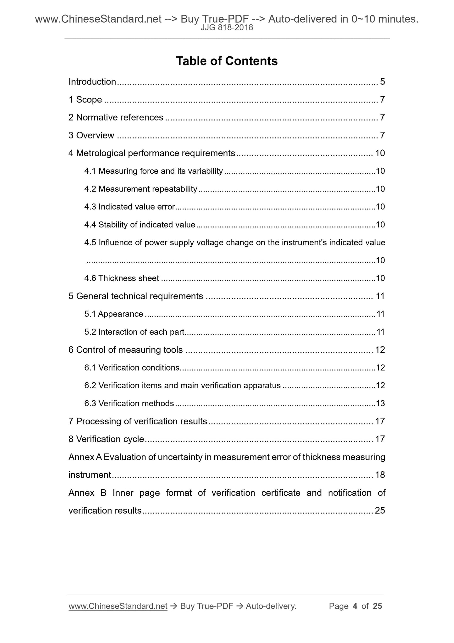
Table of Contents
Introduction ... 5
1 Scope ... 7
2 Normative references ... 7
3 Overview ... 7
4 Metrological performance requirements ... 10
4.1 Measuring force and its variability ... 10
4.2 Measurement repeatability ... 10
4.3 Indicated value error ... 10
4.4 Stability of indicated value ... 10
4.5 Influence of power supply voltage change on the instrument's indicated value
... 10
4.6 Thickness sheet ... 10
5 General technical requirements ... 11
5.1 Appearance ... 11
5.2 Interaction of each part ... 11
6 Control of measuring tools ... 12
6.1 Verification conditions ... 12
6.2 Verification items and main verification apparatus ... 12
6.3 Verification methods ... 13
7 Processing of verification results ... 17
8 Verification cycle ... 17
Annex A Evaluation of uncertainty in measurement error of thickness measuring
instrument ... 18
Annex B Inner page format of verification certificate and notification of
verification results ... 25
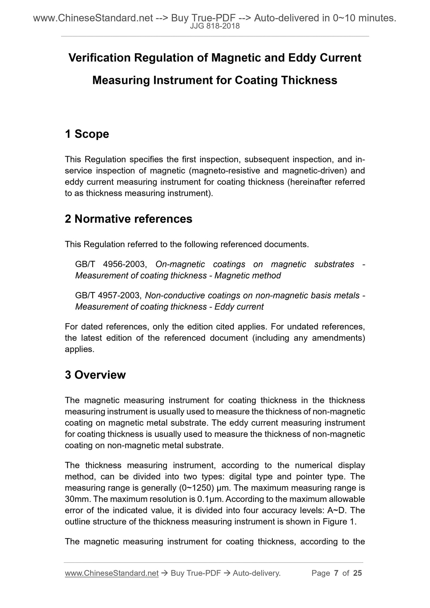
Verification Regulation of Magnetic and Eddy Current
Measuring Instrument for Coating Thickness
1 Scope
This Regulation specifies the first inspection, subsequent inspection, and in-
service inspection of magnetic (magneto-resistive and magnetic-driven) and
eddy current measuring instrument for coating thickness (hereinafter referred
to as thickness measuring instrument).
2 Normative references
This Regulation referred to the following referenced documents.
GB/T 4956-2003, On-magnetic coatings on magnetic substrates -
Measurement of coating thickness - Magnetic method
GB/T 4957-2003, Non-conductive coatings on non-magnetic basis metals -
Measurement of coating thickness - Eddy current
For dated references, only the edition cited applies. For undated references,
the latest edition of the referenced document (including any amendments)
applies.
3 Overview
The magnetic measuring instrument for coating thickness in the thickness
measuring instrument is usually used to measure the thickness of non-magnetic
coating on magnetic metal substrate. The eddy current measuring instrument
for coating thickness is usually used to measure the thickness of non-magnetic
coating on non-magnetic metal substrate.
The thickness measuring instrument, according to the numerical display
method, can be divided into two types: digital type and pointer type. The
measuring range is generally (0~1250) μm. The maximum measuring range is
30mm. The maximum resolution is 0.1μm. According to the maximum allowable
error of the indicated value, it is divided into four accuracy levels: A~D. The
outline structure of the thickness measuring instrument is shown in Figure 1.
The magnetic measuring instrument for coating thickness, according to the
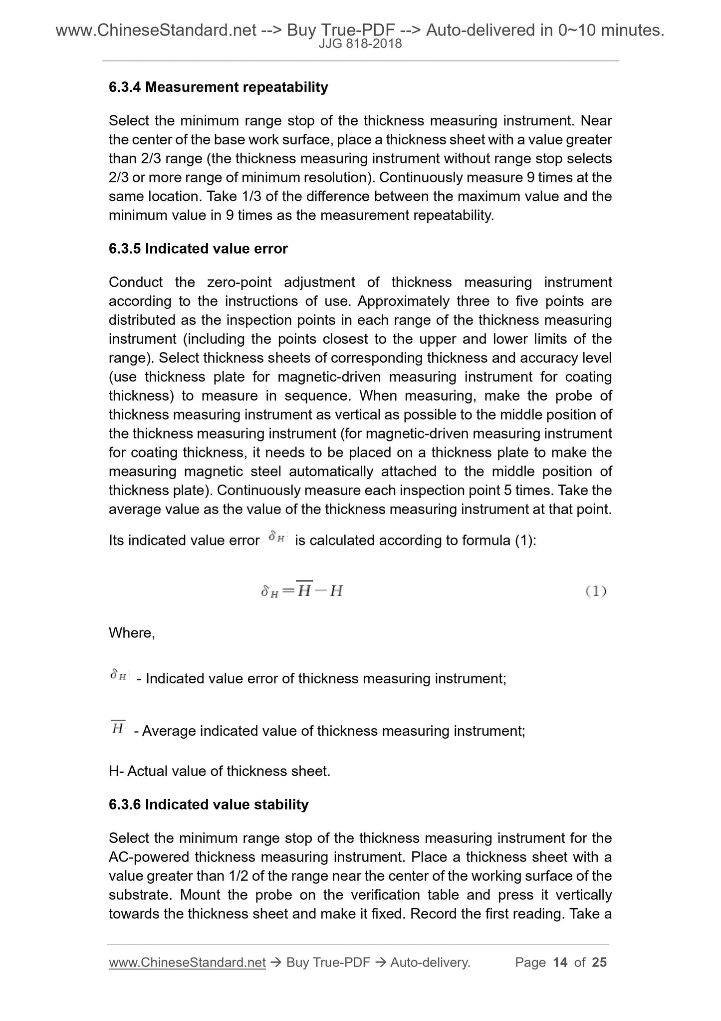
6.3.4 Measurement repeatability
Select the minimum range stop of the thickness measuring instrument. Near
the center of the base work surface, place a thickness sheet with a value greater
than 2/3 range (the thickness measuring instrument without range stop selects
2/3 or more range of minimum resolution). Continuously measure 9 times at the
same location. Take 1/3 of the difference between the maximum value and the
minimum value in 9 times as the measurement repeatability.
6.3.5 Indicated value error
Conduct the zero-point adjustment of thickness measuring instrument
according to the instructions of use. Approximately three to five points are
distributed as the inspection points in each range of the thickness measuring
instrument (including the points closest to the upper and lower limits of the
range). Select thickness sheets of corresponding thickness and accuracy level
(use thickness plate for magnetic-driven measuring instrument for coating
thickness) to measure in sequence. When measuring, make the probe of
thickness measuring instrument as vertical as possible to the middle position of
the thickness measuring instrument (for magnetic-driven measuring instrument
for coating thickness, it needs to be placed on a thickness plate to make the
measuring magnetic steel automatically attached to the middle position of
thickness plate). Continuously measure each inspection point 5 times. Take the
average value as the value of the thickness measuring instrument at that point.
Its indicated value error is calculated according to formula (1):
Where,
- Indicated value error of thickness measuring instrument;
- Average indicated value of thickness measuring instrument;
H- Actual value of thickness sheet.
6.3.6 Indicated value stability
Select the minimum range stop of the thickness measuring instrument for the
AC-powered thickness measuring instrument. Place a thickness sheet with a
value greater than 1/2 of the range near the center of the working surface of the
substrate. Mount the probe on the verification table and press it vertically
towards the thickness sheet and make it fixed. Record the first reading. Take a
reading every 15min later. Continuously record for 1h. Take the difference
between the maximum and minimum values in 5 readings as the measurement
result.
6.3.7 Influence of power supply voltage change on the instrument's
indicated value
For AC-powered thickness measuring instrument, select the minimum range
stop of thickness measuring instrument. Place a thickness sheet with a value
greater than 1/2 of the range near the center of the working surface of the
substrate (single-range thickness gauge is selected in a range of 2/3 or more
of the minimum resolution). Connect an adjustable DC stabilized power supply
or an adjustable AC transformer in series to the power terminal of the thickness
measuring instrument. Use a voltmeter to monitor. Adjust the power supply
voltage to -10% of the rated voltage permitted by the thickness measuring
instrument according to the thickness measuring instrument requirements.
Measure the thickness sheet 5 times. Take the average value as the value of
the point at the voltage. Then adjust the power supply voltage to +10% of the
rated working voltage of the thickness measuring instrument and the rated
voltage of the thickness measuring instrument. Measure the thickness sheet 5
times, respectively. Take the average value as the value of the point at the
voltage. Process the indicated value of each point according to formula (1).
6.3.8 Thickness sheet
Use digital inductive micrometers (select a 1N force probe; for a thickness sheet
not thicker than 50μm, use a flat probe) and tri-equivalent measuring block or
grating micrometer. On the flat workbench, use comparison method to measure
or direct method to measure.
Direct method measurement: First set the digital display inductive micrometer
or grating micrometer to zero. Then place the thickness sheet to be measured
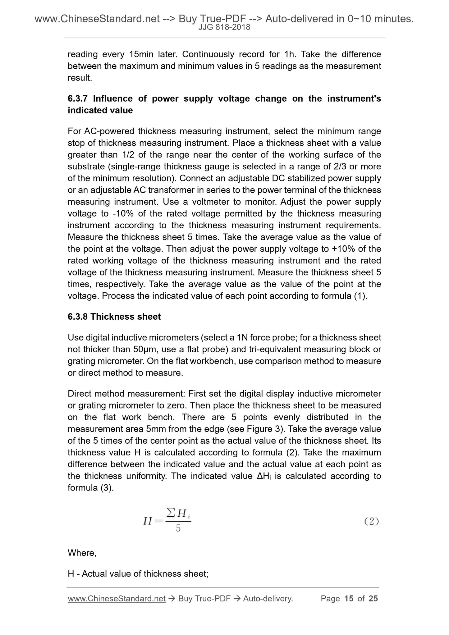
on the flat work bench. There are 5 points evenly distributed in the
measurement area 5mm from the edge (see Figure 3). Take the average value
of the 5 times of the center point as the actual value of the thickness sheet. Its
thickness value H is calculated according to formula (2). Take the maximum
difference between the indicated value and the actual value at each point as
the thickness uniformity. The indicated value ΔHi is calculated according to
formula (3).
Where,
H - Actual value of thickness sheet;
Hi - Indicated value of thickness sheet.
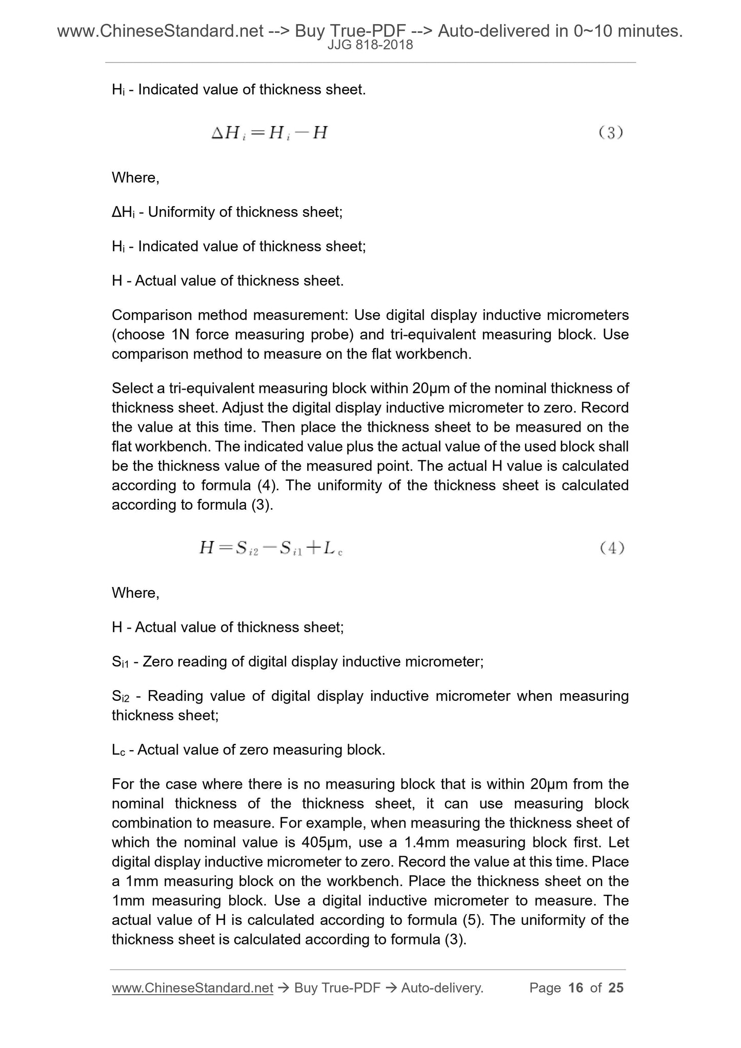
Where,
ΔHi - Uniformity of thickness sheet;
Hi - Indicated value of thickness sheet;
H - Actual value of thickness sheet.
Comparison method measurement: Use digital display inductive micrometers
(choose 1N force measuring probe) and tri-equivalent measuring block. Use
comparison method to measure on the flat workbench.
Select a tri-equivalent measuring block within 20μm of the nominal thickness of
thickness sheet. Adjust the digital display inductive micrometer to zero. Record
the value at this time. Then place the thickness sheet to be measured on the
flat workbench. The indicated value plus the actual value of the used block shall
be the thickness value of the measured point. The actual H value is calculated
according to formula (4). The uniformity of the thickness sheet is calculated
according to formula (3).
Where,
H - Actual value of thickness sheet;
Si1 - Zero reading of digital display inductive micrometer;
Si2 - Reading value of digital display inductive micrometer when measuring
thickness sheet;
Lc - Actual value of zero measuring block.
For the case where there is no measuring block that is within 20μm from the
nominal thickness of the thickness sheet, it can use measuring block
combination to measure. For example, when measuring the thickness sheet of
which the nominal value is 405μm, use a 1.4mm measuring block first. Let
digital display inductive micrometer to zero. Record the value at this time. Place
a 1mm measuring block on the workbench. Place the thickness sheet on the
1mm measuring block. Use a digital inductive micrometer to measure. The
actual value of H is calculated according to formula (5). The uniformity of the
thickness sheet is calculated according to formula (3).
Annex A
Evaluation of uncertainty in measurement error of thickness measuring
instrument
A.1 Measurement method
First, according to the instructions of use, make zero adjustment of thickness
measuring instrument. Then use the thickness measuring instrument to
measure each thickness sheet 5 times. The difference between the average
value of the thickness measuring instrument and the actual value H of the
thickness measuring instrument shall be the indicated value error δH. This
document takes 10μm, 50μm, 100μm, 500μm, 1000μm, 5000μm, and
10000μm measurement points as examples to evaluate the uncertainty of
indicated value error measurement of level-A thickness measuring instrument.
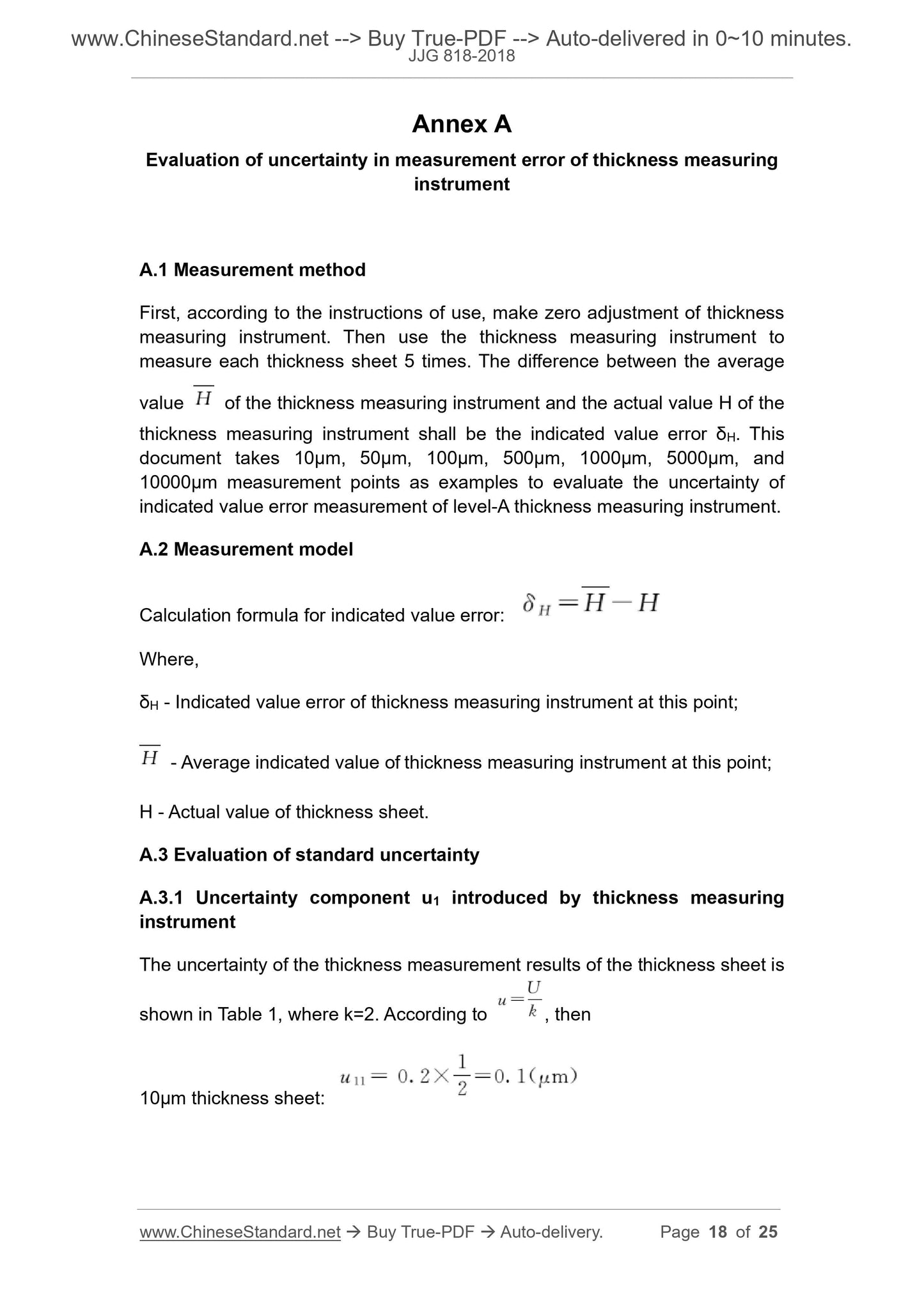
A.2 Measurement model
Calculation formula for indicated value error:
Where,
δH - Indicated value error of thickness measuring instrument at this point;
- Average indicated value of thickness measuring instrument at this point;
H - Actual value of thickness sheet.
A.3 Evaluation of standard uncertainty
A.3.1 Uncertainty component u1 introduced by thickness measuring
instrument
The uncertainty of the thickness measurement results of the thickness sheet is
shown in Table 1, where k=2. According to , then
10μm thickness sheet:
JJG 818-2018
NATIONAL METROLOGICAL VERIFICATION REGULATIONS
OF THE PEOPLE’S REPUBLIC OF CHINA
Replacing JJG 818-2005
Magnetic and Eddy Current Measuring Instrument for
Coating Thickness
ISSUED ON: DECEMBER 25, 2018
IMPLEMENTED ON: JUNE 25, 2019
Issued by: State Administration for Market Regulation
Table of Contents
Introduction ... 5
1 Scope ... 7
2 Normative references ... 7
3 Overview ... 7
4 Metrological performance requirements ... 10
4.1 Measuring force and its variability ... 10
4.2 Measurement repeatability ... 10
4.3 Indicated value error ... 10
4.4 Stability of indicated value ... 10
4.5 Influence of power supply voltage change on the instrument's indicated value
... 10
4.6 Thickness sheet ... 10
5 General technical requirements ... 11
5.1 Appearance ... 11
5.2 Interaction of each part ... 11
6 Control of measuring tools ... 12
6.1 Verification conditions ... 12
6.2 Verification items and main verification apparatus ... 12
6.3 Verification methods ... 13
7 Processing of verification results ... 17
8 Verification cycle ... 17
Annex A Evaluation of uncertainty in measurement error of thickness measuring
instrument ... 18
Annex B Inner page format of verification certificate and notification of
verification results ... 25
Verification Regulation of Magnetic and Eddy Current
Measuring Instrument for Coating Thickness
1 Scope
This Regulation specifies the first inspection, subsequent inspection, and in-
service inspection of magnetic (magneto-resistive and magnetic-driven) and
eddy current measuring instrument for coating thickness (hereinafter referred
to as thickness measuring instrument).
2 Normative references
This Regulation referred to the following referenced documents.
GB/T 4956-2003, On-magnetic coatings on magnetic substrates -
Measurement of coating thickness - Magnetic method
GB/T 4957-2003, Non-conductive coatings on non-magnetic basis metals -
Measurement of coating thickness - Eddy current
For dated references, only the edition cited applies. For undated references,
the latest edition of the referenced document (including any amendments)
applies.
3 Overview
The magnetic measuring instrument for coating thickness in the thickness
measuring instrument is usually used to measure the thickness of non-magnetic
coating on magnetic metal substrate. The eddy current measuring instrument
for coating thickness is usually used to measure the thickness of non-magnetic
coating on non-magnetic metal substrate.
The thickness measuring instrument, according to the numerical display
method, can be divided into two types: digital type and pointer type. The
measuring range is generally (0~1250) μm. The maximum measuring range is
30mm. The maximum resolution is 0.1μm. According to the maximum allowable
error of the indicated value, it is divided into four accuracy levels: A~D. The
outline structure of the thickness measuring instrument is shown in Figure 1.
The magnetic measuring instrument for coating thickness, according to the
6.3.4 Measurement repeatability
Select the minimum range stop of the thickness measuring instrument. Near
the center of the base work surface, place a thickness sheet with a value greater
than 2/3 range (the thickness measuring instrument without range stop selec...
Share
