1
/
of
10
PayPal, credit cards. Download editable-PDF and invoice in 1 second!
JJG 882-2019 English PDF (JJG882-2019)
JJG 882-2019 English PDF (JJG882-2019)
Regular price
$450.00 USD
Regular price
Sale price
$450.00 USD
Unit price
/
per
Shipping calculated at checkout.
Couldn't load pickup availability
Delivery: 3 seconds. Download true-PDF + Invoice.
Get QUOTATION in 1-minute: Click JJG 882-2019
Historical versions: JJG 882-2019
Preview True-PDF (Reload/Scroll if blank)
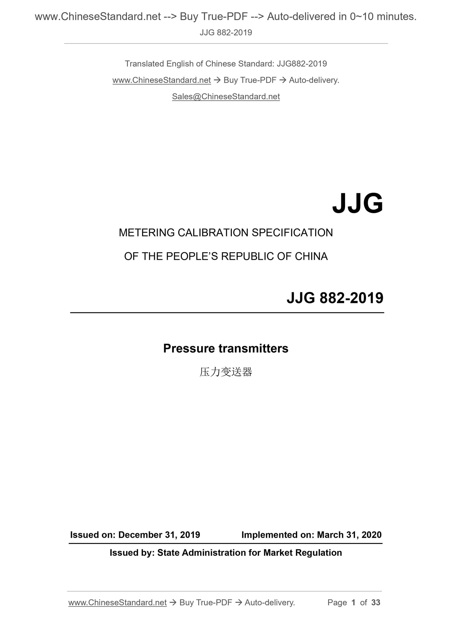
JJG 882-2019: Pressure Transmitters
JJG 882-2019
JJG
METERING CALIBRATION SPECIFICATION
OF THE PEOPLE’S REPUBLIC OF CHINA
Pressure transmitters
压力变送器
ISSUED ON: DECEMBER 31, 2019
IMPLEMENTED ON: MARCH 31, 2020
Issued by: State Administration for Market Regulation
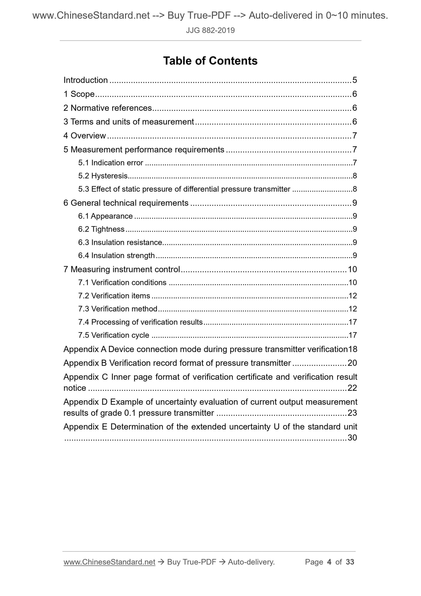
Table of Contents
Introduction ... 5
1 Scope ... 6
2 Normative references ... 6
3 Terms and units of measurement ... 6
4 Overview ... 7
5 Measurement performance requirements ... 7
5.1 Indication error ... 7
5.2 Hysteresis... 8
5.3 Effect of static pressure of differential pressure transmitter ... 8
6 General technical requirements ... 9
6.1 Appearance ... 9
6.2 Tightness ... 9
6.3 Insulation resistance... 9
6.4 Insulation strength ... 9
7 Measuring instrument control ... 10
7.1 Verification conditions ... 10
7.2 Verification items ... 12
7.3 Verification method ... 12
7.4 Processing of verification results ... 17
7.5 Verification cycle ... 17
Appendix A Device connection mode during pressure transmitter verification18
Appendix B Verification record format of pressure transmitter ... 20
Appendix C Inner page format of verification certificate and verification result
notice ... 22
Appendix D Example of uncertainty evaluation of current output measurement
results of grade 0.1 pressure transmitter ... 23
Appendix E Determination of the extended uncertainty U of the standard unit
... 30
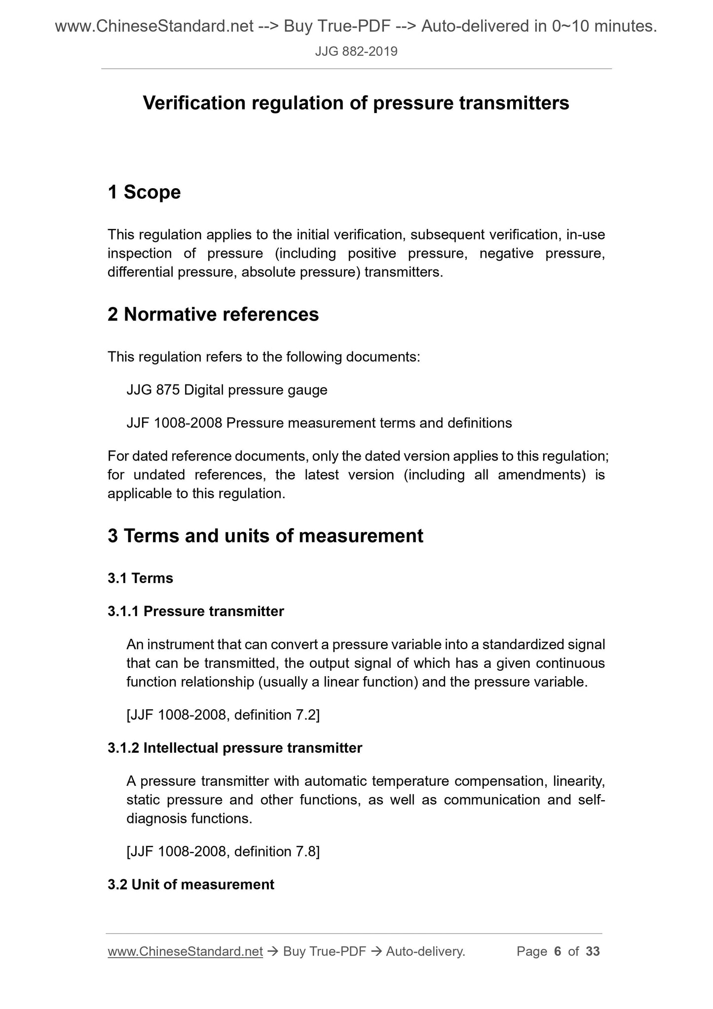
Verification regulation of pressure transmitters
1 Scope
This regulation applies to the initial verification, subsequent verification, in-use
inspection of pressure (including positive pressure, negative pressure,
differential pressure, absolute pressure) transmitters.
2 Normative references
This regulation refers to the following documents:
JJG 875 Digital pressure gauge
JJF 1008-2008 Pressure measurement terms and definitions
For dated reference documents, only the dated version applies to this regulation;
for undated references, the latest version (including all amendments) is
applicable to this regulation.
3 Terms and units of measurement
3.1 Terms
3.1.1 Pressure transmitter
An instrument that can convert a pressure variable into a standardized signal
that can be transmitted, the output signal of which has a given continuous
function relationship (usually a linear function) and the pressure variable.
[JJF 1008-2008, definition 7.2]
3.1.2 Intellectual pressure transmitter
A pressure transmitter with automatic temperature compensation, linearity,
static pressure and other functions, as well as communication and self-
diagnosis functions.
[JJF 1008-2008, definition 7.8]
3.2 Unit of measurement
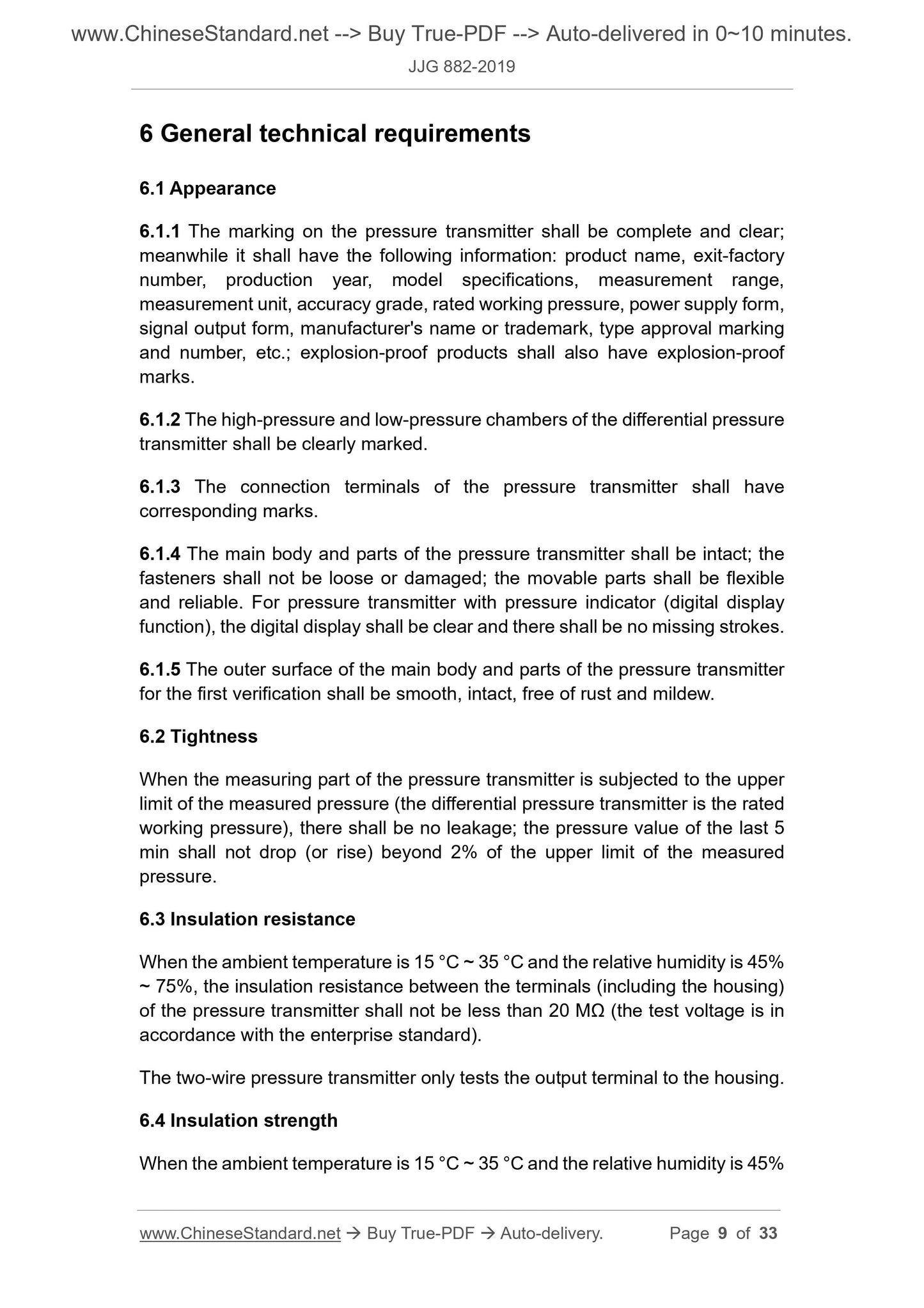
6 General technical requirements
6.1 Appearance
6.1.1 The marking on the pressure transmitter shall be complete and clear;
meanwhile it shall have the following information: product name, exit-factory
number, production year, model specifications, measurement range,
measurement unit, accuracy grade, rated working pressure, power supply form,
signal output form, manufacturer's name or trademark, type approval marking
and number, etc.; explosion-proof products shall also have explosion-proof
marks.
6.1.2 The high-pressure and low-pressure chambers of the differential pressure
transmitter shall be clearly marked.
6.1.3 The connection terminals of the pressure transmitter shall have
corresponding marks.
6.1.4 The main body and parts of the pressure transmitter shall be intact; the
fasteners shall not be loose or damaged; the movable parts shall be flexible
and reliable. For pressure transmitter with pressure indicator (digital display
function), the digital display shall be clear and there shall be no missing strokes.
6.1.5 The outer surface of the main body and parts of the pressure transmitter
for the first verification shall be smooth, intact, free of rust and mildew.
6.2 Tightness
When the measuring part of the pressure transmitter is subjected to the upper
limit of the measured pressure (the differential pressure transmitter is the rated
working pressure), there shall be no leakage; the pressure value of the last 5
min shall not drop (or rise) beyond 2% of the upper limit of the measured
pressure.
6.3 Insulation resistance
When the ambient temperature is 15 °C ~ 35 °C and the relative humidity is 45%
~ 75%, the insulation resistance between the terminals (including the housing)
of the pressure transmitter shall not be less than 20 MΩ (the test voltage is in
accordance with the enterprise standard).
The two-wire pressure transmitter only tests the output terminal to the housing.
6.4 Insulation strength
When the ambient temperature is 15 °C ~ 35 °C and the relative humidity is 45%
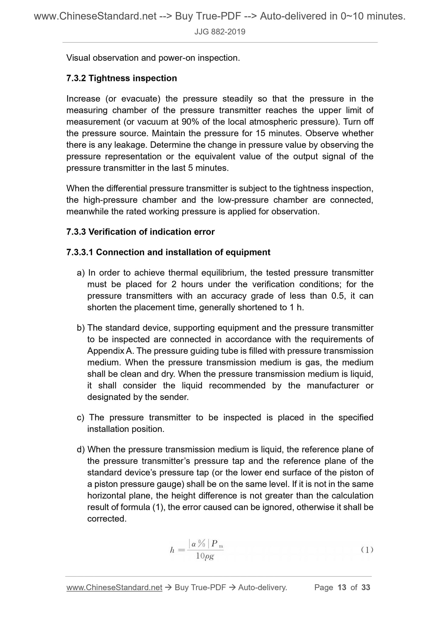
Visual observation and power-on inspection.
7.3.2 Tightness inspection
Increase (or evacuate) the pressure steadily so that the pressure in the
measuring chamber of the pressure transmitter reaches the upper limit of
measurement (or vacuum at 90% of the local atmospheric pressure). Turn off
the pressure source. Maintain the pressure for 15 minutes. Observe whether
there is any leakage. Determine the change in pressure value by observing the
pressure representation or the equivalent value of the output signal of the
pressure transmitter in the last 5 minutes.
When the differential pressure transmitter is subject to the tightness inspection,
the high-pressure chamber and the low-pressure chamber are connected,
meanwhile the rated working pressure is applied for observation.
7.3.3 Verification of indication error
7.3.3.1 Connection and installation of equipment
a) In order to achieve thermal equilibrium, the tested pressure transmitter
must be placed for 2 hours under the verification conditions; for the
pressure transmitters with an accuracy grade of less than 0.5, it can
shorten the placement time, generally shortened to 1 h.
b) The standard device, supporting equipment and the pressure transmitter
to be inspected are connected in accordance with the requirements of
Appendix A. The pressure guiding tube is filled with pressure transmission
medium. When the pressure transmission medium is gas, the medium
shall be clean and dry. When the pressure transmission medium is liquid,
it shall consider the liquid recommended by the manufacturer or
designated by the sender.
c) The pressure transmitter to be inspected is placed in the specified
installation position.
d) When the pressure transmission medium is liquid, the reference plane of
the pressure transmitter’s pressure tap and the reference plane of the
standard device’s pressure tap (or the lower end surface of the piston of
a piston pressure gauge) shall be on the same level. If it is not in the same
horizontal plane, the height difference is not greater than the calculation
result of formula (1), the error caused can be ignored, otherwise it shall be
corrected.
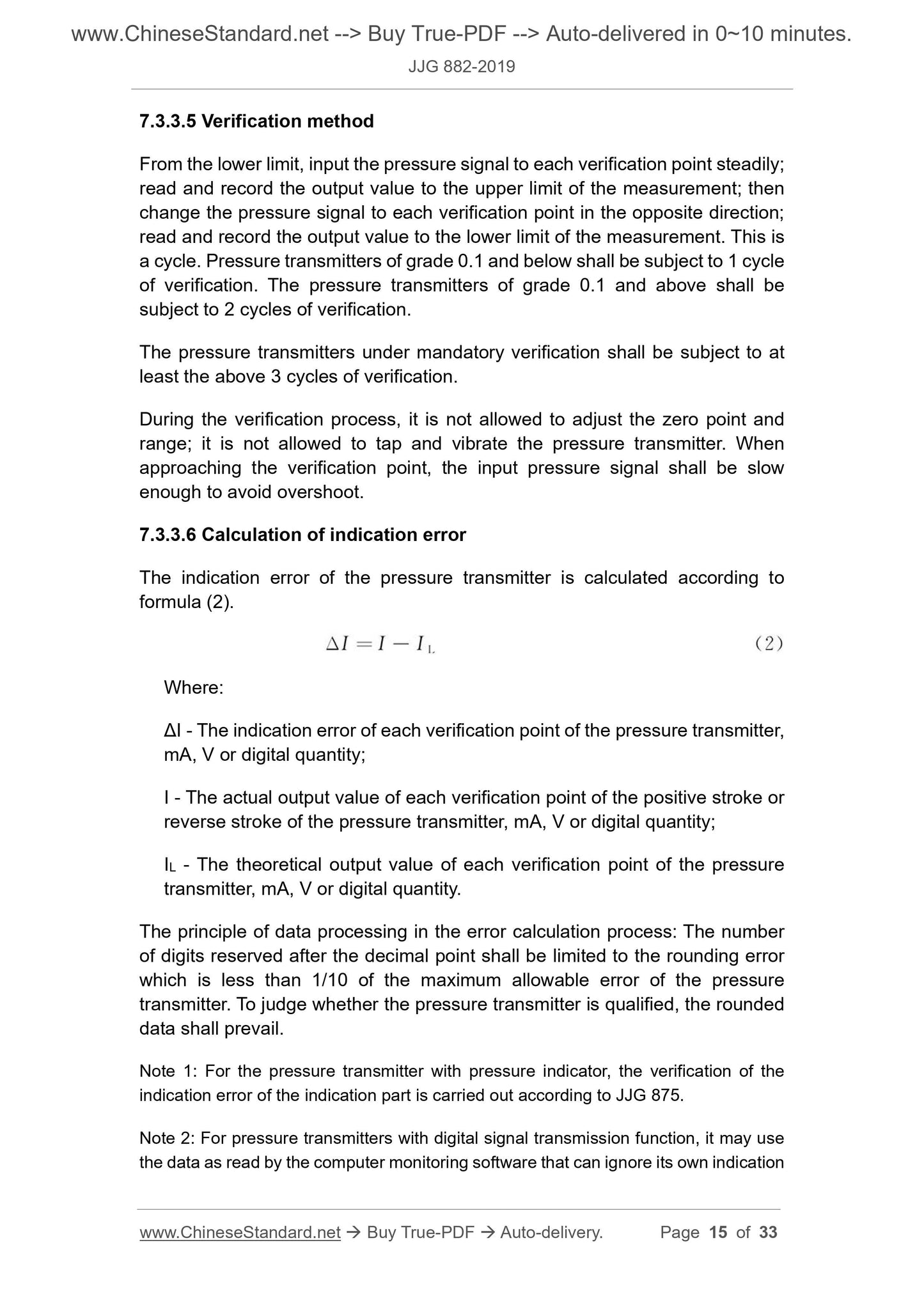
7.3.3.5 Verification method
From the lower limit, input the pressure signal to each verification point steadily;
read and record the output value to the upper limit of the measurement; then
change the pressure signal to each verification point in the opposite direction;
read and record the output value to the lower limit of the measurement. This is
a cycle. Pressure transmitters of grade 0.1 and below shall be subject to 1 cycle
of verification. The pressure transmitters of grade 0.1 and above shall be
subject to 2 cycles of verification.
The pressure transmitters under manda...
Share
