1
/
of
8
www.ChineseStandard.us -- Field Test Asia Pte. Ltd.
QC/T 1006-2015 English PDF (QC/T1006-2015)
QC/T 1006-2015 English PDF (QC/T1006-2015)
Regular price
$170.00
Regular price
Sale price
$170.00
Unit price
/
per
Shipping calculated at checkout.
Couldn't load pickup availability
QC/T 1006-2015: Specifications and bench test methods of automobile antilock braking system solenoid modulator for pneumatic
Delivery: 9 seconds. Download (& Email) true-PDF + Invoice.
Get Quotation: Click QC/T 1006-2015 (Self-service in 1-minute)
Historical versions (Master-website): QC/T 1006-2015
Preview True-PDF (Reload/Scroll-down if blank)
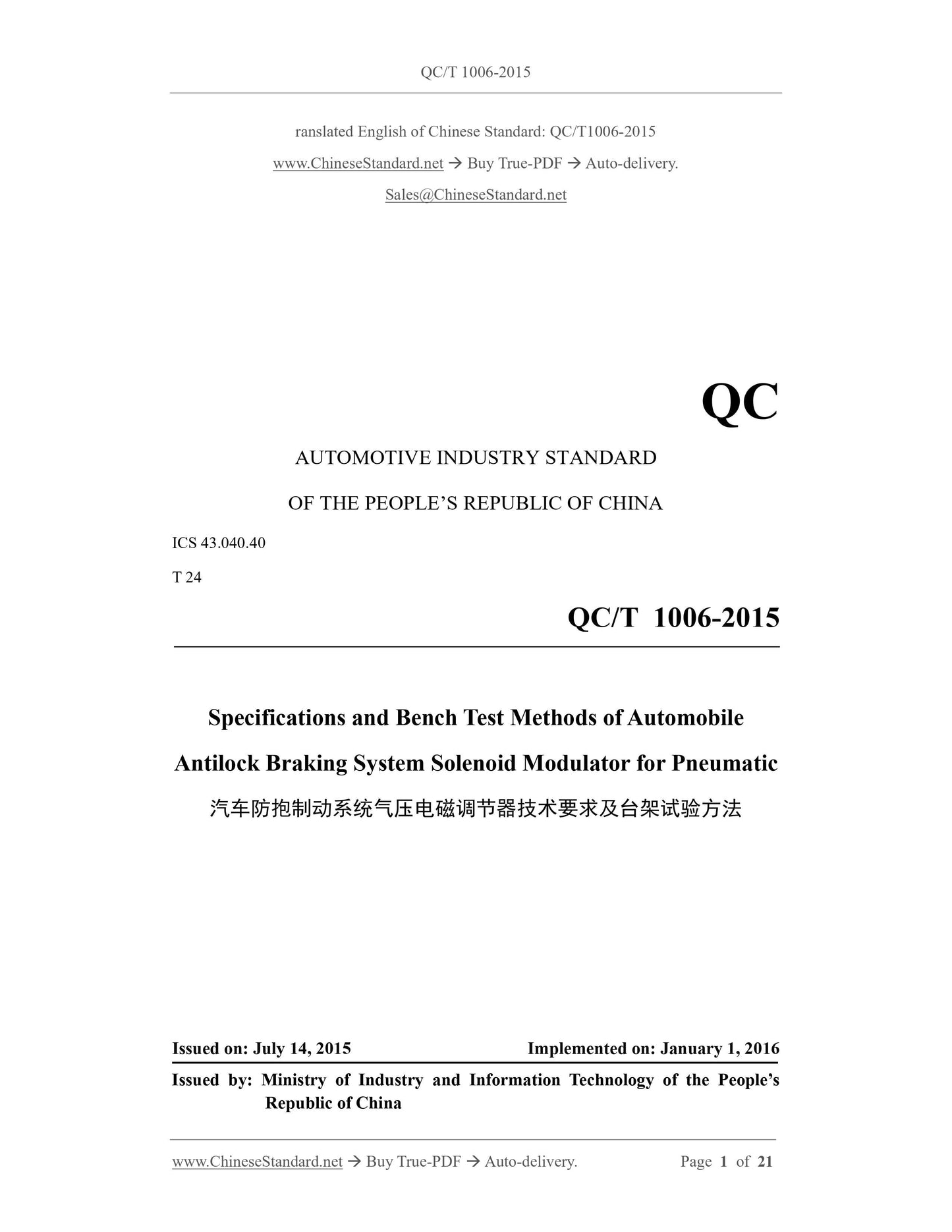
QC/T 1006-2015
ranslated English of Chinese Standard. QC/T1006-2015
QC
AUTOMOTIVE INDUSTRY STANDARD
ICS 43.040.40
T 24
Specifications and Bench Test Methods of Automobile
Antilock Braking System Solenoid Modulator for Pneumatic
ISSUED ON. JULY 14, 2015
IMPLEMENTED ON. JANUARY 1, 2016
Issued by. Ministry of Industry and Information Technology of the People’s
Republic of China
Table of Contents
Foreword... 6
1 Scope... 7
2 Normative References... 7
3 Terms and Definitions... 7
4 Performance Requirements... 9
5 Test Related Requirements... 13
6 Test Methods... 15
Specifications and Bench Test Methods of Automobile
Antilock Braking System Solenoid Modulator for Pneumatic
1 Scope
This Standard specifies the terms and definitions, performance requirements, and bench test
methods for automobile antilock braking systems (hereinafter referred to as "ABS") solenoid
modulator for pneumatic.
This Standard applies to various types of ABS solenoid modulator for pneumatic.
2 Normative References
The following documents are essential to the application of this Document. For the dated
documents, only the versions with the dates indicated are applicable to this Document; for the
undated documents, only the latest version (including all the amendments) is applicable to this
Document.
GB/T 5620-2002 Road vehicles - Braking of automotive vehicles and their trailers –
Vocabulary
GB/T 10125-2012 Corrosion tests in artificial atmospheres - Salt spray tests
QC/T 572 Directives for motor vehicle cleanness - Measuring method
3 Terms and Definitions
For the purposes of this Document, the terms and definitions given in GB/T 5620-2002 and the
following apply.
3.1 Rated working pressure; Pe
The working air pressure that is specified in the technical documentation of the ABS solenoid
modulator for pneumatic.
3.2 Rated working voltage; Ve
The working voltage that is specified in the technical documentation of the ABS solenoid
modulator for pneumatic.
3.3 Time of pressure boosting
The time that is required for the pressure-raising stage during a braking process (with brake
pressure and working voltage as the ordinate and time as the abscissa), starting from when the
inlet valve of the ABS solenoid modulator for pneumatic is de-energized (before which, its
exhaust valve has been de-energized), to when it is required for the outlet pressure of the ABS
solenoid modulator for pneumatic to rise to 90% of the rated working pressure.
3.4 Time of pressure decompressing
The time that is required for pressure decompressing stage during a braking process (with brake
pressure and working voltage as the ordinate and time as the abscissa), starting from when the
intake valve and exhaust valve of the ABS solenoid modulator for pneumatic are energized at
the same time (before that, the intake valve and exhaust valve have been de-energized), to when
the outlet pressure of the ABS solenoid modulator for pneumatic to drop from the rated working
pressure to 10% of the rated lower working pressure.
3.5 Pressure boosting starting
The process that the pressure changes from the original state to 6 kPa higher than the original
state.
3.6 Pressure decompressing starting
The process that the pressure changes from the original state to 6 kPa lower than the original
state pressure.
3.7 Lag time of pressure boosting
The lag time between the pressure signal and the electrical signal when the pressure boosting
starting is conducted during the pressure boosting process.
3.8 Lag time of pressure decompressing
The lag time between the pressure signal and the electrical signal when the pressure
decompressing starting is conducting during the pressure decompressing process.
3.9 State of pressure boosting
That is, the normal braking state. The intake valve and exhaust valve of the ABS solenoid
modulator for pneumatic are both in a non-energized state.
3.10 State of pressure retaining
The state that the intake valve of the ABS solenoid modulator for pneumatic is energized and
the exhaust valve is de-energized.
3.11 State of pressure decompressing
The state that both intake valve and exhaust valve of the ABS solenoid modulator for pneumatic
are energized.
4 Performance Requirements
4.1 Winding withstand voltage characteristics
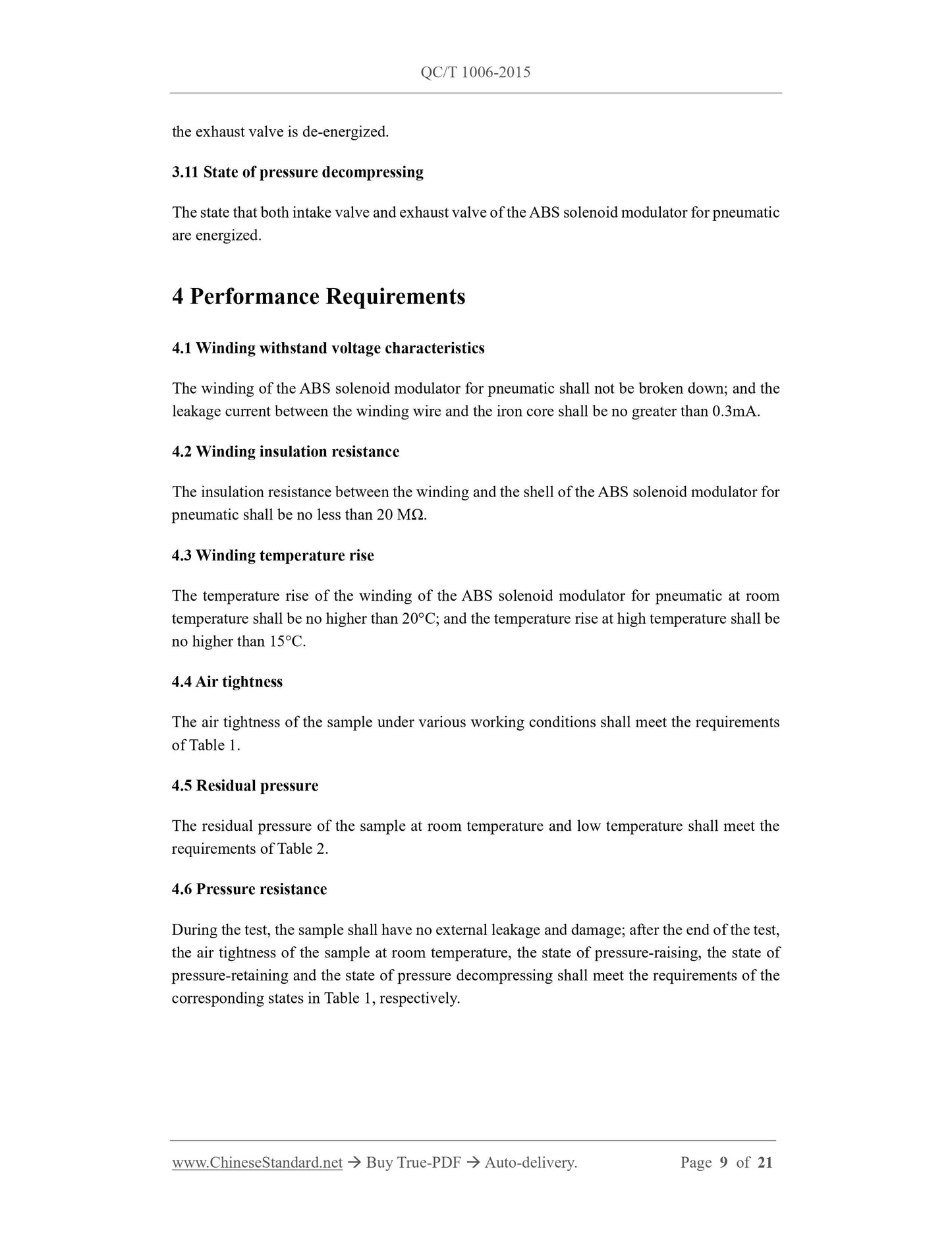
The winding of the ABS solenoid modulator for pneumatic shall not be broken down; and the
leakage current between the winding wire and the iron core shall be no greater than 0.3mA.
4.2 Winding insulation resistance
The insulation resistance between the winding and the shell of the ABS solenoid modulator for
pneumatic shall be no less than 20 MΩ.
4.3 Winding temperature rise
The temperature rise of the winding of the ABS solenoid modulator for pneumatic at room
temperature shall be no higher than 20°C; and the temperature rise at high temperature shall be
no higher than 15°C.
4.4 Air tightness
The air tightness of the sample under various working conditions shall meet the requirements
of Table 1.
4.5 Residual pressure
The residual pressure of the sample at room temperature and low temperature shall meet the
requirements of Table 2.
4.6 Pressure resistance
During the test, the sample shall have no external leakage and damage; after the end of the test,
the air tightness of the sample at room temperature, the state of pressure-raising, the state of
pressure-retaining and the state of pressure decompressing shall meet the requirements of the
corresponding states in Table 1, respectively.
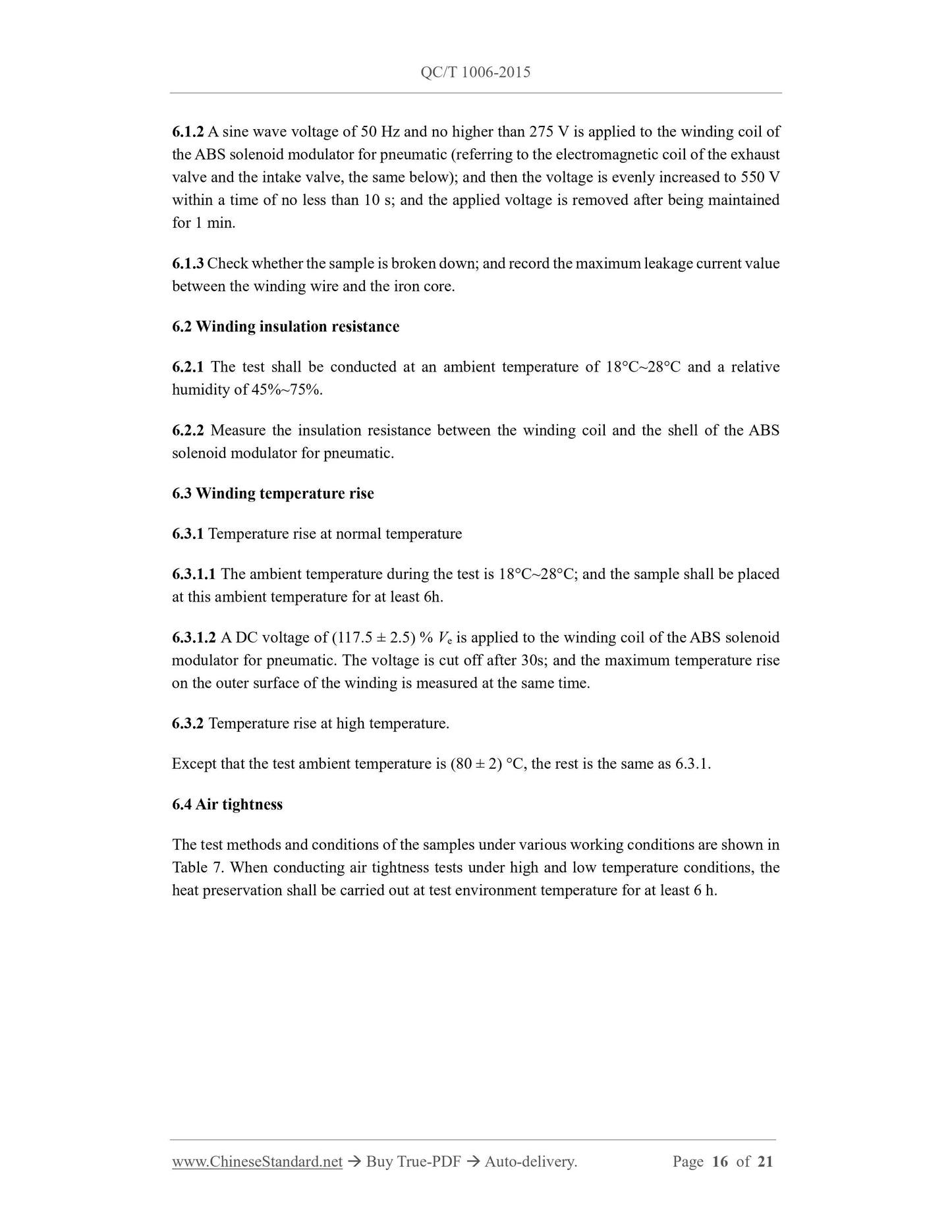
6.1.2 A sine wave voltage of 50 Hz and no higher than 275 V is applied to the winding coil of
the ABS solenoid modulator for pneumatic (referring to the electromagnetic coil of the exhaust
valve and the intake valve, the same below); and then the voltage is evenly increased to 550 V
within a time of no less than 10 s; and the applied voltage is removed after being maintained
for 1 min.
6.1.3 Check whether the sample is broken down; and record the maximum leakage current value
between the winding wire and the iron core.
6.2 Winding insulation resistance
6.2.1 The test shall be conducted at an ambient temperature of 18°C~28°C and a relative
humidity of 45%~75%.
6.2.2 Measure the insulation resistance between the winding coil and the shell of the ABS
solenoid modulator for pneumatic.
6.3 Winding temperature rise
6.3.1 Temperature rise at normal temperature
6.3.1.1 The ambient temperature during the test is 18°C~28°C; and the sample shall be placed
at this ambient temperature for at least 6h.
6.3.1.2 A DC voltage of (117.5 ± 2.5) % Ve is applied to the winding coil of the ABS solenoid
modulator for pneumatic. The voltage is cut off after 30s; and the maximum temperature rise
on the outer surface of the winding is measured at the same time.
6.3.2 Temperature rise at high temperature.
Except that the test ambient temperature is (80 ± 2) °C, the rest is the same as 6.3.1.
6.4 Air tightness
The test methods and conditions of the samples under various working conditions are shown in
Table 7.When conducting air tightness tests under high and low temperature conditions, the
heat preservation shall be carried out at test environment temperature for at least 6 h.
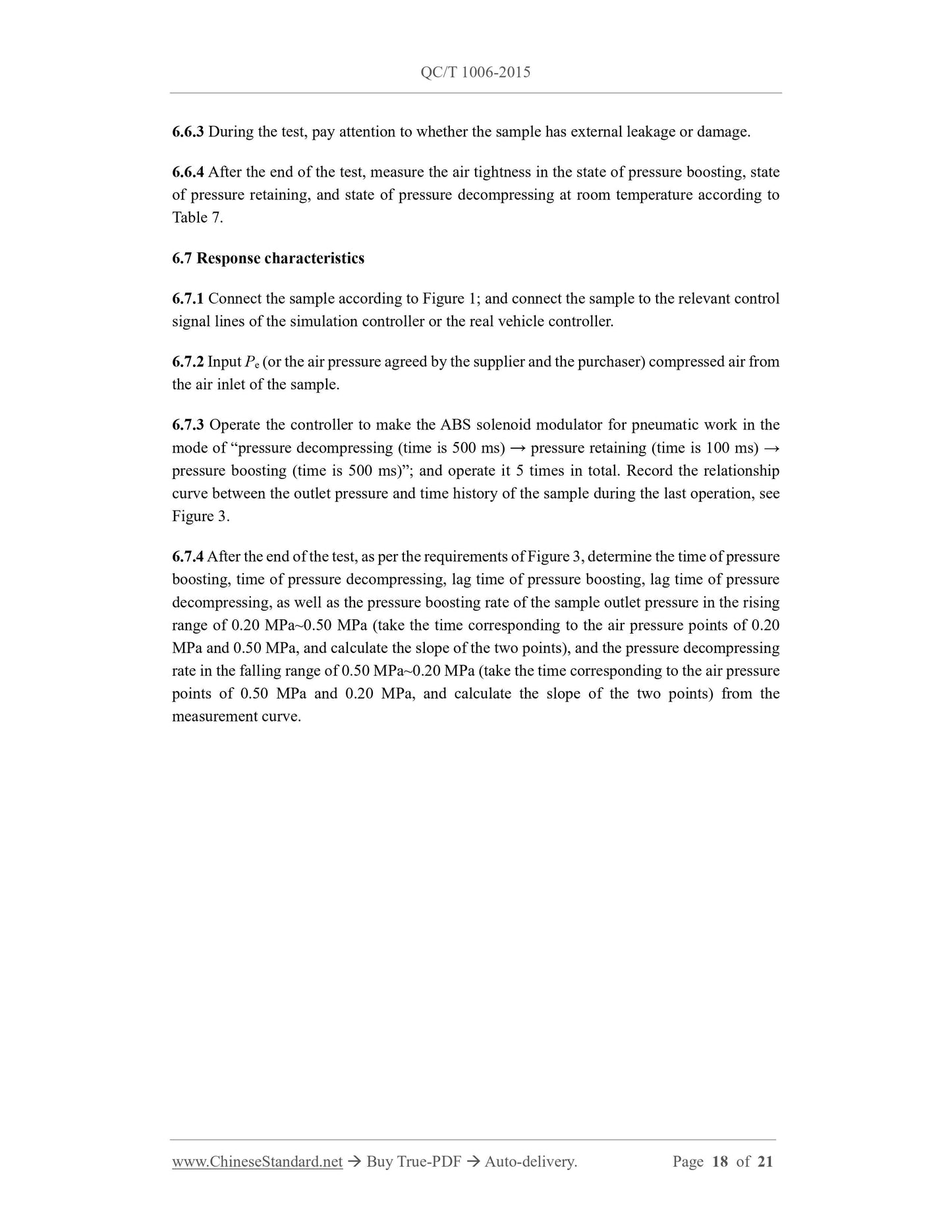
6.6.3 During the test, pay attention to whether the sample has external leakage or damage.
6.6.4 After the end of the test, measure the air tightness in the state of pressure boosting, state
of pressure retaining, and state of pressure decompressing at room temperature according to
Table 7.
6.7 Response characteristics
6.7.1 Connect the sample according to Figure 1; and connect the sample to the relevant control
signal lines of the simulation controller or the real vehicle controller.
6.7.2 Input Pe (or the air pressure agreed by the supplier and the purchaser) compressed air from
the air inlet of the sample.
6.7.3 Operate the controller to make the ABS solenoid modulator for pneumatic work in the
mode of “pressure decompressing (time is 500 ms) → pressure retaining (time is 100 ms) →
pressure boosting (time is 500 ms)”; and operate it 5 times in total. Record the relationship
curve between the outlet pressure and time history of the sample during the last operation, see
Figure 3.
6.7.4 After the end of the test, as per the requirements of Figure 3, determine the time of pressure
boosting, time of pressure decompressing, lag time of pressure boosting, lag time of pressure
decompressing, as well as the pressure boosting rate of the sample outlet pressure in the rising
range of 0.20 MPa~0.50 MPa (take the time corresponding to the air pressure points of 0.20
MPa and 0.50 MPa, and calculate the slope of the two points), and the pressure decompressing
rate in the falling range of 0.50 MPa~0.20 MPa (take the time corresponding to the air pressure
points of 0.50 MPa and 0.20 MPa, and calculate the slope of the two points) from the
measurement curve.
QC/T 1006-2015
ranslated English of Chinese Standard. QC/T1006-2015
QC
AUTOMOTIVE INDUSTRY STANDARD
ICS 43.040.40
T 24
Specifications and Bench Test Methods of Automobile
Antilock Braking System Solenoid Modulator for Pneumatic
ISSUED ON. JULY 14, 2015
IMPLEMENTED ON. JANUARY 1, 2016
Issued by. Ministry of Industry and Information Technology of the People’s
Republic of China
Table of Contents
Foreword... 6
1 Scope... 7
2 Normative References... 7
3 Terms and Definitions... 7
4 Performance Requirements... 9
5 Test Related Requirements... 13
6 Test Methods... 15
Specifications and Bench Test Methods of Automobile
Antilock Braking System Solenoid Modulator for Pneumatic
1 Scope
This Standard specifies the terms and definitions, performance requirements, and bench test
methods for automobile antilock braking systems (hereinafter referred to as "ABS") solenoid
modulator for pneumatic.
This Standard applies to various types of ABS solenoid modulator for pneumatic.
2 Normative References
The following documents are essential to the application of this Document. For the dated
documents, only the versions with the dates indicated are applicable to this Document; for the
undated documents, only the latest version (including all the amendments) is applicable to this
Document.
GB/T 5620-2002 Road vehicles - Braking of automotive vehicles and their trailers –
Vocabulary
GB/T 10125-2012 Corrosion tests in artificial atmospheres - Salt spray tests
QC/T 572 Directives for motor vehicle cleanness - Measuring method
3 Terms and Definitions
For the purposes of this Document, the terms and definitions given in GB/T 5620-2002 and the
following apply.
3.1 Rated working pressure; Pe
The working air pressure that is specified in the technical documentation of the ABS solenoid
modulator for pneumatic.
3.2 Rated working voltage; Ve
The working voltage that is specified in the technical documentation of the ABS solenoid
modulator for pneumatic.
3.3 Time of pressure boosting
The time that is required for the pressure-raising stage during a braking process (with brake
pressure and working voltage as the ordinate and time as the abscissa), starting from when the
inlet valve of the ABS solenoid modulator for pneumatic is de-energized (before which, its
exhaust valve has been de-energized), to when it is required for the outlet pressure of the ABS
solenoid modulator for pneumatic to rise to 90% of the rated working pressure.
3.4 Time of pressure decompressing
The time that is required for pressure decompressing stage during a braking process (with brake
pressure and working voltage as the ordinate and time as the abscissa), starting from when the
intake valve and exhaust valve of the ABS solenoid modulator for pneumatic are energized at
the same time (before that, the intake valve and exhaust valve have been de-energized), to when
the outlet pressure of the ABS solenoid modulator for pneumatic to drop from the rated working
pressure to 10% of the rated lower working pressure.
3.5 Pressure boosting starting
The process that the pressure changes from the original state to 6 kPa higher than the original
state.
3.6 Pressure decompressing starting
The process that the pressure changes from the original state to 6 kPa lower than the original
state pressure.
3.7 Lag time of pressure boosting
The lag time between the pressure signal and the electrical signal when the pressure boosting
starting is conducted during the pressure boosting process.
3.8 Lag time of pressure decompressing
The lag time between the pressure signal and the electrical signal when the pressure
decompressing starting is conducting during the pressure decompressing process.
3.9 State of pressure boosting
That is, the normal braking state. The intake valve and exhaust valve of the ABS solenoid
modulator for pneumatic are both in a non-energized state.
3.10 State of pressure retaining
The state that the intake valve of the ABS solenoid modulator for pneumatic is energized and
the exhaust valve is de-energized.
3.11 State of pressure decompressing
The state that both intake valve and exhaust valve of the ABS solenoid modulator for pneumatic
are energized.
4 Performance Requirements
4.1 Winding withstand voltage characteristics
The winding of the ABS solenoid modulator for pneumatic shall not be broken down; and the
leakage current between the winding wire and the iron core shall be no greater than 0.3mA.
4.2 Winding insulation resistance
The insulation resistance between the winding and the shell of the ABS solenoid modulator for
pneumatic shall be no less than 20 MΩ.
4.3 Winding temperature rise
The temperature rise of the winding of the ABS solenoid modulator for pneumatic at room
temperature shall be no higher than 20°C; and the temperature rise at high temperature shall be <...
Share
