1
/
of
12
PayPal, credit cards. Download editable-PDF & invoice in 1 second!
QC/T 1067.1-2017 English PDF (QC/T1067.1-2017)
QC/T 1067.1-2017 English PDF (QC/T1067.1-2017)
Regular price
$495.00 USD
Regular price
Sale price
$495.00 USD
Unit price
/
per
Shipping calculated at checkout.
Couldn't load pickup availability
Delivery: 3 seconds. Download true-PDF + Invoice.
Get QUOTATION in 1-minute: Click QC/T 1067.1-2017
Historical versions: QC/T 1067.1-2017
Preview True-PDF (Reload/Scroll if blank)
QC/T 1067.1-2017: Connector used in automobile wire harness and electrical device--Part 1: Definition, test method and requirement
QC/T 1067.1-2017
AUTOMOTIVE INDUSTRY STANDARD
OF THE PEOPLE’S REPUBLIC OF CHINA
ICS 43.040.10
T 36
Replacing QC/T 417.1-2001
Connector used in automobile wire harness and
electrical device - Part 1: Definition, test method and
requirement
ISSUED ON: JANUARY 09, 2017
IMPLEMENTED ON: JULY 01, 2017
Issued by: Ministry of Industry and Information Technology of the
People's Republic of China
Table of Contents
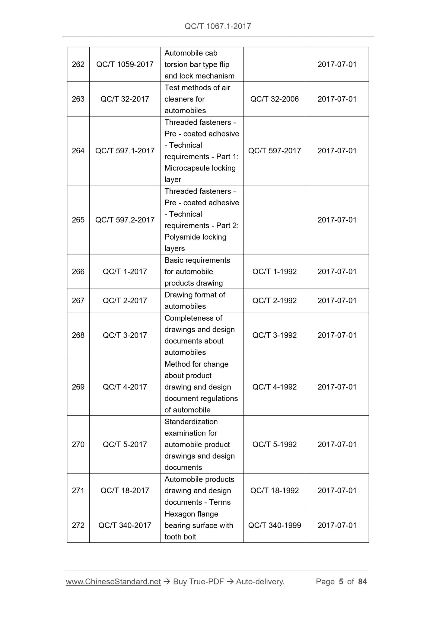
Announcement ... 3
Foreword ... 9
1 Scope ... 12
2 Normative references ... 12
3 Terms and definitions ... 13
4 Tests and requirements ... 15
Annex A (normative) Test method for terminal current carrying capacity ... 74
Annex B (normative) Power spectral density (PSD) or acceleration and
frequency ... 76
Annex C (informative) Type and size of fixing structure of connector ... 81
Connector used in automobile wire harness and
electrical device - Part 1: Definition, test method and
requirement
1 Scope
This Standard specifies the definition, general performance requirements as
well specific test methods for automobile connector.
This Standard is applicable to low-voltage connector (voltage is not higher than
60V) and high-voltage connector (voltage is higher than 60V but not higher than
600V) used in automobile wire harness and electrical device, including in-line
connector and device connector.
2 Normative references
The following referenced documents are indispensable for the application of
this document. For dated references, only the edition cited applies. For undated
references, the latest edition of the referenced document (including any
amendments) applies.
GB 252, Guideline for occupational hazard prevention and control in small
and medium bag-making industry
GB 484, Petrol (gasoline) for motor vehicles
GB 5337, Nomenclature and terminology for automotive electrical equipment,
lighting and instrumentation
GB 11118.1, Hydraulic fluids of mineral oil type and synthetic hydrocarbon
type
GB 11121, Gasoline engine oils
GB 12981, Motor vehicle brake fluids
GB/T 2423.17, Environmental testing for electric and electronic products -
Part 2: Test method - Test Ka: Salt mist
GB/T 25085, Road vehicles - 60 V and 600 V single-core cables
3.10 terminal position assurance (TPA)
Mechanism to ensure terminal is installed in place and provide terminal locking
force separately.
3.11 primary lock reinforcement (PLR)
Mechanism to ensure that terminal primary lock structure is maintained in
correct position.
3.12 connector position assurance (CPA)
An additional locking mechanism on locking mechanism of connector
4 Tests and requirements
4.1 Sample pre-treatment
Before all tests are conducted, it shall place the samples in an environment that
the room temperature is (23±5)°C and the relevant humidity is 45%~75% for
24h.
4.1.1 Test requirements
All tests shall be conducted at a room temperature of (23±5)°C. All cavities of
the connector shall be tested.
The cable shall meet the requirements of GB/T 25085 or it shall be agreed by
the supplier and the purchaser. All cables used shall be recorded in the test
report.
Each test and each test sample must not affect each other. For example, in the
high temperature box, it must keep a certain distance between test samples.
They must not touch other nor stack.
During the entire test process, it is not allowed to apply lubricant or other
additives on the surfaces of plug terminal and socket terminal, except the
lubricants remained during production.
4.1.2 Default test errors
The default test errors are expressed as a percentage of the nominal value
(Table 1).
Table 1 -- Default test errors
Temperature ±3°C
Voltage ±5%
4.2 Appearance
4.2.1 Devices
Camera, video recorder, magnifier (if necessary).
4.2.2 Methods
The test sequence is as follows:
1) Before conducting the test, visually check the test sample. Record
manufacturing and material defects such as cracks, discoloration, burrs,
etc. Take photos, videos of the test sample or prepare a sample that is not
used for the test for each test group, so as to compare the specimen after
the test;
2) After the test, visually check each sample that has been tested and record
all observable changes. Compare the sample that has been tested with
the sample that has not been tested, photos or videos in step 1). Record
all the differences in the test report.
4.2.3 Requirements
The sample shall not have defects such as swelling, corrosion, discoloration,
wear of contact plating, physical deformation, cracking that affect the function
of the product.
4.3 Plug-unplug cycle
4.3.1 Devices
It shall be agreed by the supplier and the purchaser.
4.3.2 Methods
According to the provisions of Table 5, complete the plug-unplug cycle of
connector or terminal. When only terminals are subject to the plug-unplug cycle,
during the test process, it shall ensure that the plug-unplug cycle is conducted
along with the centerline of the terminal.
4.3.3 Requirements
There are no damages that shall affect the follow-up tests.
4.4 Terminal-to-terminal insertion and extraction forces
4.4.1 Devices
Plug-unplug testing machine.
4.4.2 Methods
The test sequence is as follows:
1) Prepare 10 pairs of terminals. Number each pair of terminals;
2) Fix 1 pair of terminals on the fixture. Ensure that the plug-unplug is
conducted along with the centerline of the terminal;
3) Insert the terminal at a uniform speed of 50mm/min. Record the peak force
required for in-place insertion (the first insertion force);
4) Separate the terminal at a uniform speed of 50mm/min. Record the peak
force required for complete separation (the first extraction force);
5) According to the number of plug-unplug specified in Table 5, repeat step
3) and step 4). Record the last extraction force);
6) Conduct step 2) ~ step 5) to each pair of terminals.
4.4.3 Requirements
The appearance shall meet the requirements of 4.2. The metal substrate of the
contact area shall not be exposed. The insertion and extraction forces shall
meet the requirements of the product design documents or be agreed between
the supplier and the purchaser.
4.5 Terminal bending resistance
4.5.1 Devices
Special fixture, force tester with peak reading characteristics.
4.5.2 Methods
This test is not applicable to the situation that cable attachment and terminal
insertion direction form 90°.
The test sequence is as follows:
1) Confirm the type of test terminal according to Figure 4;
2) Number each housing and each terminal hole;
3) Use the fixture to fix housing;
4) Use the force tester to clamp the cable at a position 20mm from the
insulation support;
5) Insert the terminal at a uniform speed of 50mm/min into the housing.
Continuously apply a force till it reaches the value specified in Table 12 or
the plastic is broken or terminal is broken when it does not reach the
specified value;
Alternatives:
A. Crimp the terminal on the solid metal rod. Measure the terminal’s
insertion force and thrust force;
B. Cut off the cable from the insulation crimp. Use a rod that is close to
cable diameter to push the cable that is left at the end of the terminal.
6) Record the peak force (i.e. insertion force) required for the terminal to
insert into the housing before it reaches the expected stop position and
the force that the housing withstands...
Get QUOTATION in 1-minute: Click QC/T 1067.1-2017
Historical versions: QC/T 1067.1-2017
Preview True-PDF (Reload/Scroll if blank)
QC/T 1067.1-2017: Connector used in automobile wire harness and electrical device--Part 1: Definition, test method and requirement
QC/T 1067.1-2017
AUTOMOTIVE INDUSTRY STANDARD
OF THE PEOPLE’S REPUBLIC OF CHINA
ICS 43.040.10
T 36
Replacing QC/T 417.1-2001
Connector used in automobile wire harness and
electrical device - Part 1: Definition, test method and
requirement
ISSUED ON: JANUARY 09, 2017
IMPLEMENTED ON: JULY 01, 2017
Issued by: Ministry of Industry and Information Technology of the
People's Republic of China
Table of Contents
Announcement ... 3
Foreword ... 9
1 Scope ... 12
2 Normative references ... 12
3 Terms and definitions ... 13
4 Tests and requirements ... 15
Annex A (normative) Test method for terminal current carrying capacity ... 74
Annex B (normative) Power spectral density (PSD) or acceleration and
frequency ... 76
Annex C (informative) Type and size of fixing structure of connector ... 81
Connector used in automobile wire harness and
electrical device - Part 1: Definition, test method and
requirement
1 Scope
This Standard specifies the definition, general performance requirements as
well specific test methods for automobile connector.
This Standard is applicable to low-voltage connector (voltage is not higher than
60V) and high-voltage connector (voltage is higher than 60V but not higher than
600V) used in automobile wire harness and electrical device, including in-line
connector and device connector.
2 Normative references
The following referenced documents are indispensable for the application of
this document. For dated references, only the edition cited applies. For undated
references, the latest edition of the referenced document (including any
amendments) applies.
GB 252, Guideline for occupational hazard prevention and control in small
and medium bag-making industry
GB 484, Petrol (gasoline) for motor vehicles
GB 5337, Nomenclature and terminology for automotive electrical equipment,
lighting and instrumentation
GB 11118.1, Hydraulic fluids of mineral oil type and synthetic hydrocarbon
type
GB 11121, Gasoline engine oils
GB 12981, Motor vehicle brake fluids
GB/T 2423.17, Environmental testing for electric and electronic products -
Part 2: Test method - Test Ka: Salt mist
GB/T 25085, Road vehicles - 60 V and 600 V single-core cables
3.10 terminal position assurance (TPA)
Mechanism to ensure terminal is installed in place and provide terminal locking
force separately.
3.11 primary lock reinforcement (PLR)
Mechanism to ensure that terminal primary lock structure is maintained in
correct position.
3.12 connector position assurance (CPA)
An additional locking mechanism on locking mechanism of connector
4 Tests and requirements
4.1 Sample pre-treatment
Before all tests are conducted, it shall place the samples in an environment that
the room temperature is (23±5)°C and the relevant humidity is 45%~75% for
24h.
4.1.1 Test requirements
All tests shall be conducted at a room temperature of (23±5)°C. All cavities of
the connector shall be tested.
The cable shall meet the requirements of GB/T 25085 or it shall be agreed by
the supplier and the purchaser. All cables used shall be recorded in the test
report.
Each test and each test sample must not affect each other. For example, in the
high temperature box, it must keep a certain distance between test samples.
They must not touch other nor stack.
During the entire test process, it is not allowed to apply lubricant or other
additives on the surfaces of plug terminal and socket terminal, except the
lubricants remained during production.
4.1.2 Default test errors
The default test errors are expressed as a percentage of the nominal value
(Table 1).
Table 1 -- Default test errors
Temperature ±3°C
Voltage ±5%
4.2 Appearance
4.2.1 Devices
Camera, video recorder, magnifier (if necessary).
4.2.2 Methods
The test sequence is as follows:
1) Before conducting the test, visually check the test sample. Record
manufacturing and material defects such as cracks, discoloration, burrs,
etc. Take photos, videos of the test sample or prepare a sample that is not
used for the test for each test group, so as to compare the specimen after
the test;
2) After the test, visually check each sample that has been tested and record
all observable changes. Compare the sample that has been tested with
the sample that has not been tested, photos or videos in step 1). Record
all the differences in the test report.
4.2.3 Requirements
The sample shall not have defects such as swelling, corrosion, discoloration,
wear of contact plating, physical deformation, cracking that affect the function
of the product.
4.3 Plug-unplug cycle
4.3.1 Devices
It shall be agreed by the supplier and the purchaser.
4.3.2 Methods
According to the provisions of Table 5, complete the plug-unplug cycle of
connector or terminal. When only terminals are subject to the plug-unplug cycle,
during the test process, it shall ensure that the plug-unplug cycle is conducted
along with the centerline of the terminal.
4.3.3 Requirements
There are no damages that shall affect the follow-up tests.
4.4 Terminal-to-terminal insertion and extraction forces
4.4.1 Devices
Plug-unplug testing machine.
4.4.2 Methods
The test sequence is as follows:
1) Prepare 10 pairs of terminals. Number each pair of terminals;
2) Fix 1 pair of terminals on the fixture. Ensure that the plug-unplug is
conducted along with the centerline of the terminal;
3) Insert the terminal at a uniform speed of 50mm/min. Record the peak force
required for in-place insertion (the first insertion force);
4) Separate the terminal at a uniform speed of 50mm/min. Record the peak
force required for complete separation (the first extraction force);
5) According to the number of plug-unplug specified in Table 5, repeat step
3) and step 4). Record the last extraction force);
6) Conduct step 2) ~ step 5) to each pair of terminals.
4.4.3 Requirements
The appearance shall meet the requirements of 4.2. The metal substrate of the
contact area shall not be exposed. The insertion and extraction forces shall
meet the requirements of the product design documents or be agreed between
the supplier and the purchaser.
4.5 Terminal bending resistance
4.5.1 Devices
Special fixture, force tester with peak reading characteristics.
4.5.2 Methods
This test is not applicable to the situation that cable attachment and terminal
insertion direction form 90°.
The test sequence is as follows:
1) Confirm the type of test terminal according to Figure 4;
2) Number each housing and each terminal hole;
3) Use the fixture to fix housing;
4) Use the force tester to clamp the cable at a position 20mm from the
insulation support;
5) Insert the terminal at a uniform speed of 50mm/min into the housing.
Continuously apply a force till it reaches the value specified in Table 12 or
the plastic is broken or terminal is broken when it does not reach the
specified value;
Alternatives:
A. Crimp the terminal on the solid metal rod. Measure the terminal’s
insertion force and thrust force;
B. Cut off the cable from the insulation crimp. Use a rod that is close to
cable diameter to push the cable that is left at the end of the terminal.
6) Record the peak force (i.e. insertion force) required for the terminal to
insert into the housing before it reaches the expected stop position and
the force that the housing withstands...
Share