1
/
of
12
www.ChineseStandard.us -- Field Test Asia Pte. Ltd.
QC/T 1164-2022 English PDF (QC/T1164-2022)
QC/T 1164-2022 English PDF (QC/T1164-2022)
Regular price
$275.00
Regular price
Sale price
$275.00
Unit price
/
per
Shipping calculated at checkout.
Couldn't load pickup availability
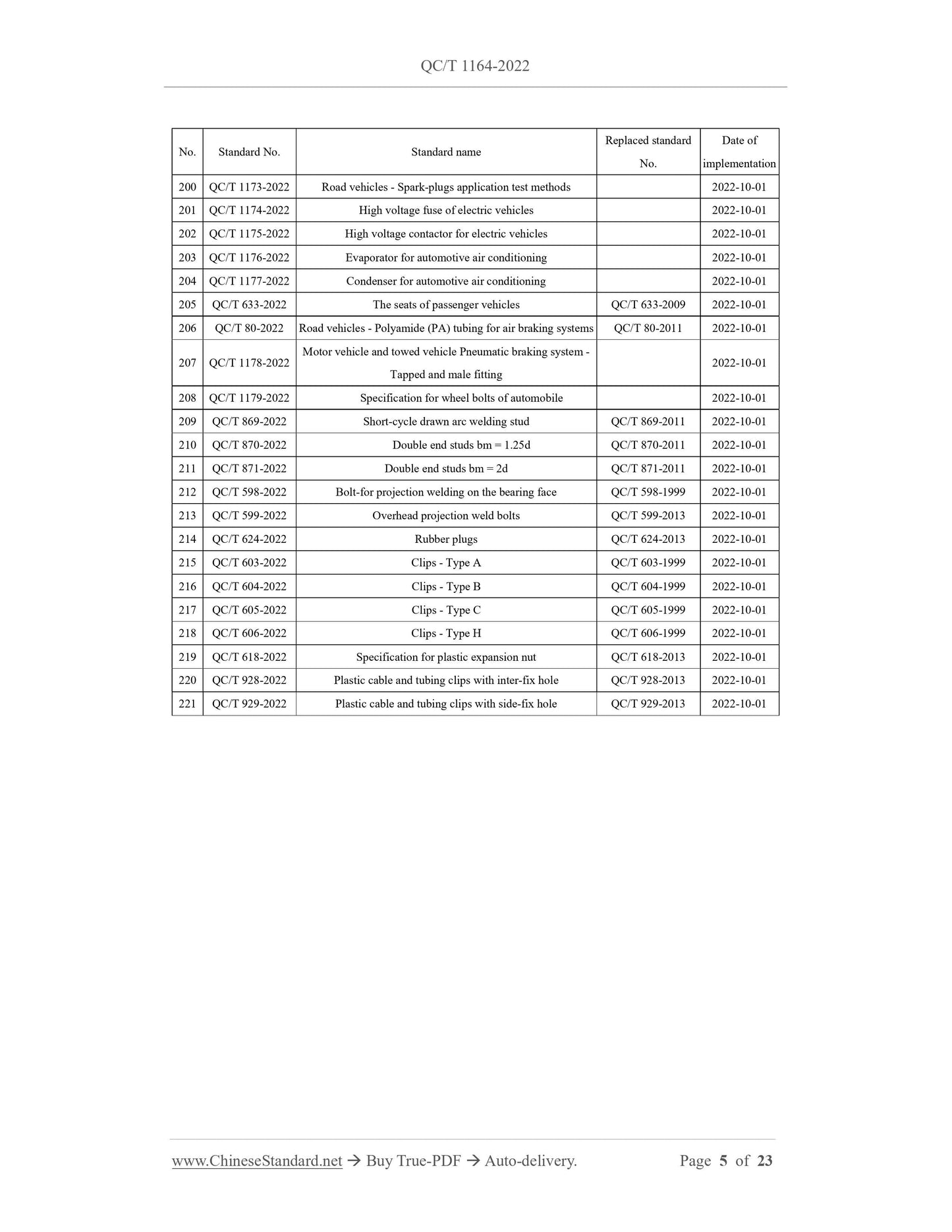
QC/T 1164-2022: Natural gas filter for road vehicle
Delivery: 9 seconds. Download (& Email) true-PDF + Invoice.
Get Quotation: Click QC/T 1164-2022 (Self-service in 1-minute)
Historical versions (Master-website): QC/T 1164-2022
Preview True-PDF (Reload/Scroll-down if blank)
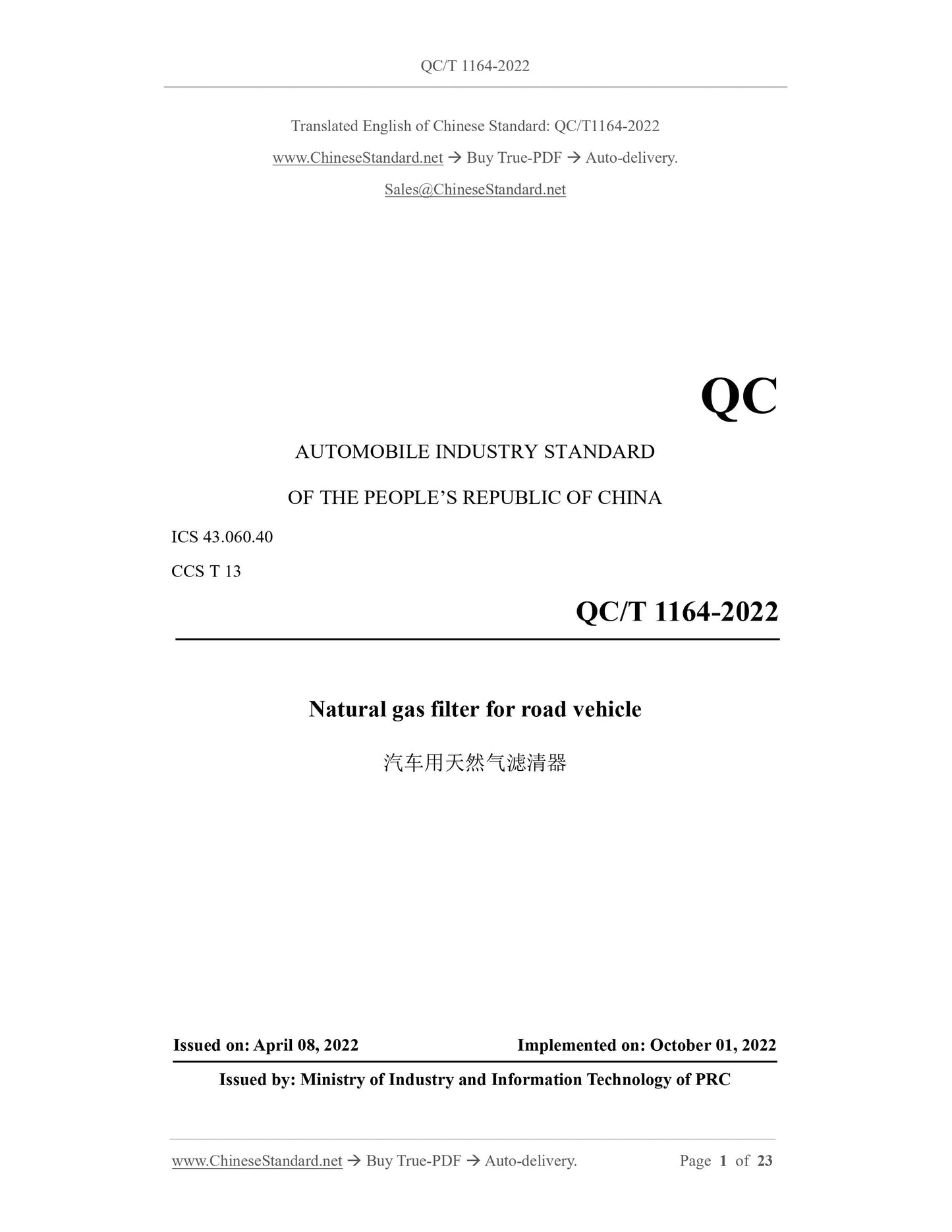
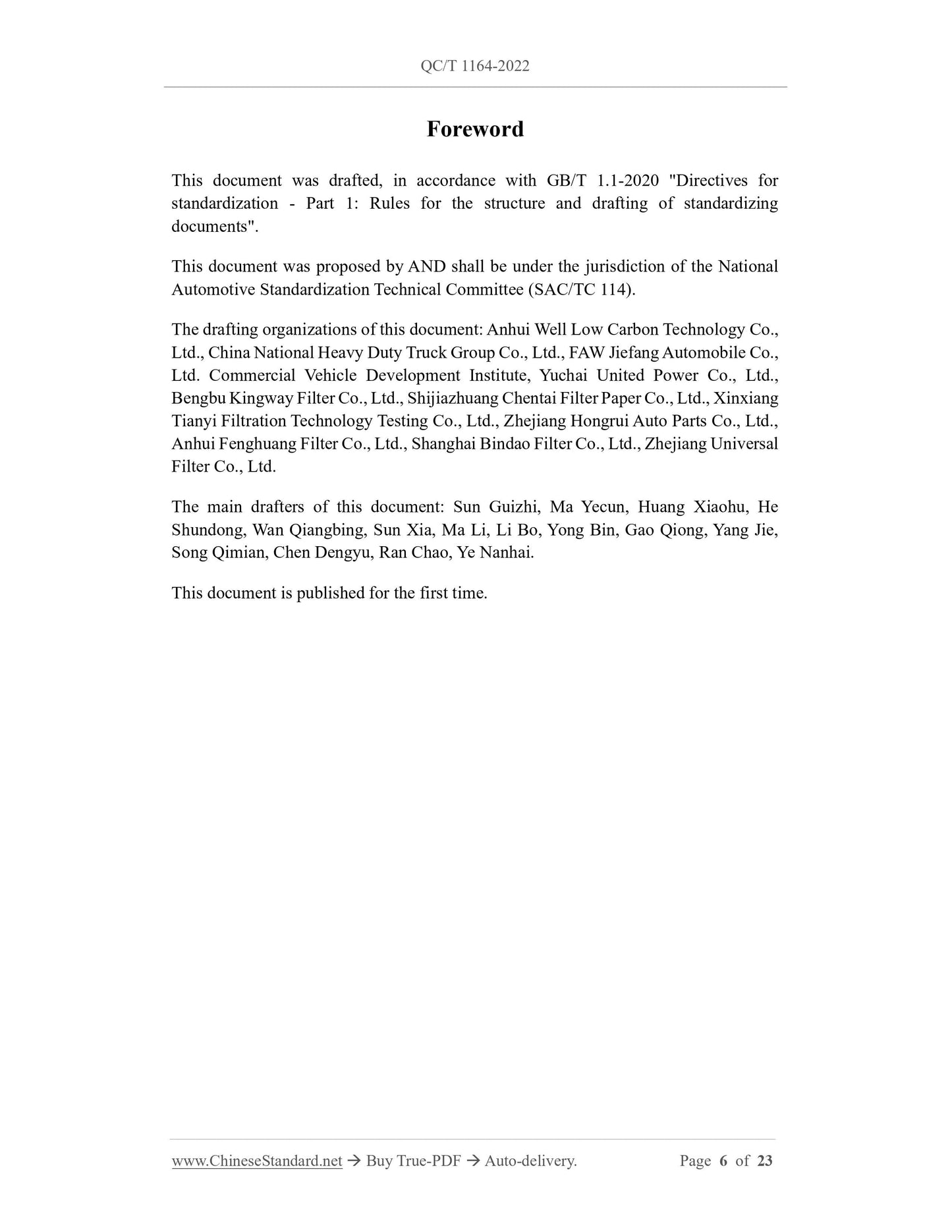
QC/T 1164-2022
QC
AUTOMOBILE INDUSTRY STANDARD
OF THE PEOPLE’S REPUBLIC OF CHINA
ICS 43.060.40
CCS T 13
Natural gas filter for road vehicle
ISSUED ON: APRIL 08, 2022
IMPLEMENTED ON: OCTOBER 01, 2022
Issued by: Ministry of Industry and Information Technology of PRC
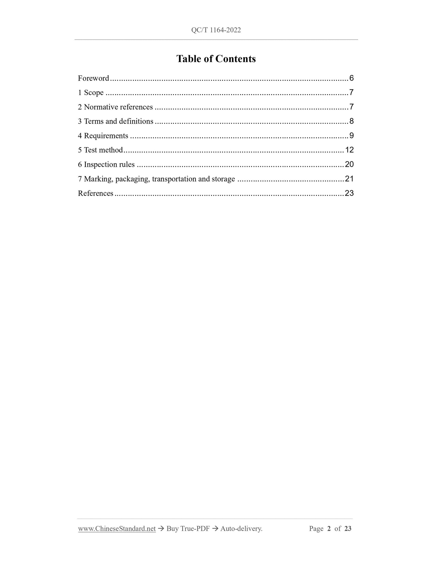
Table of Contents
Foreword ... 6
1 Scope ... 7
2 Normative references ... 7
3 Terms and definitions ... 8
4 Requirements ... 9
5 Test method ... 12
6 Inspection rules ... 20
7 Marking, packaging, transportation and storage ... 21
References ... 23
Natural gas filter for road vehicle
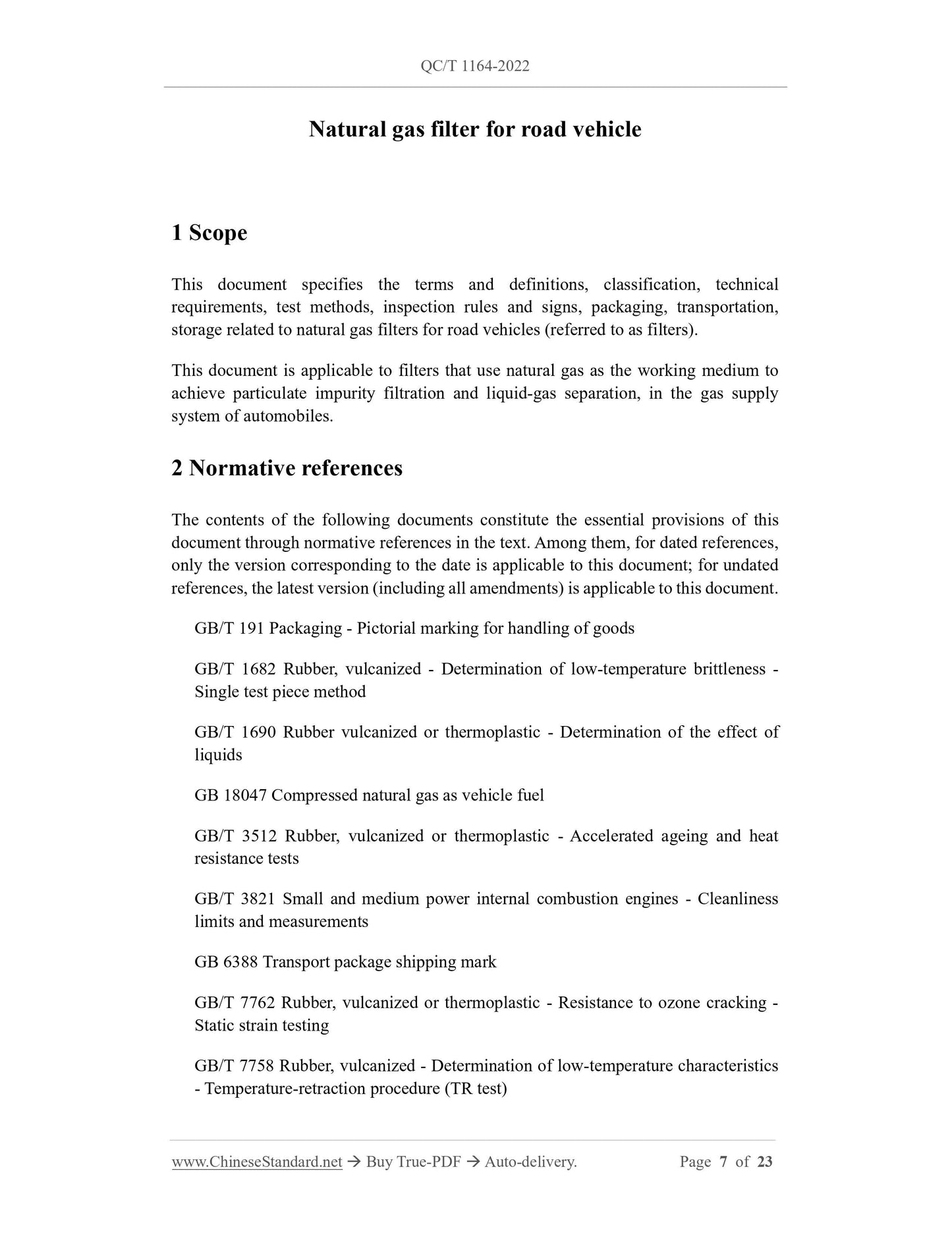
1 Scope
This document specifies the terms and definitions, classification, technical
requirements, test methods, inspection rules and signs, packaging, transportation,
storage related to natural gas filters for road vehicles (referred to as filters).
This document is applicable to filters that use natural gas as the working medium to
achieve particulate impurity filtration and liquid-gas separation, in the gas supply
system of automobiles.
2 Normative references
The contents of the following documents constitute the essential provisions of this
document through normative references in the text. Among them, for dated references,
only the version corresponding to the date is applicable to this document; for undated
references, the latest version (including all amendments) is applicable to this document.
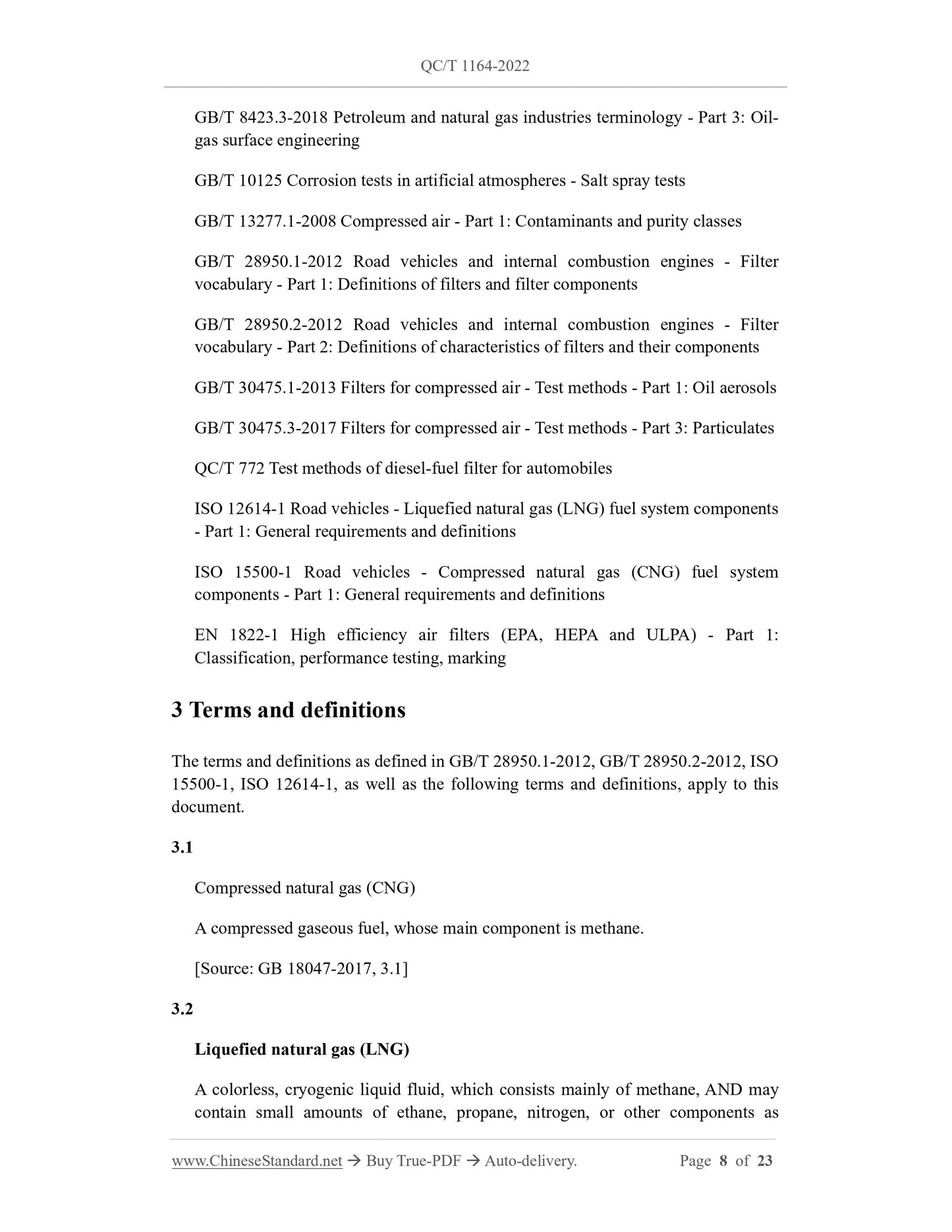
GB/T 191 Packaging - Pictorial marking for handling of goods
GB/T 1682 Rubber, vulcanized - Determination of low-temperature brittleness -
Single test piece method
GB/T 1690 Rubber vulcanized or thermoplastic - Determination of the effect of
liquids
GB 18047 Compressed natural gas as vehicle fuel
GB/T 3512 Rubber, vulcanized or thermoplastic - Accelerated ageing and heat
resistance tests
GB/T 3821 Small and medium power internal combustion engines - Cleanliness
limits and measurements
GB 6388 Transport package shipping mark
GB/T 7762 Rubber, vulcanized or thermoplastic - Resistance to ozone cracking -
Static strain testing
GB/T 7758 Rubber, vulcanized - Determination of low-temperature characteristics
- Temperature-retraction procedure (TR test)
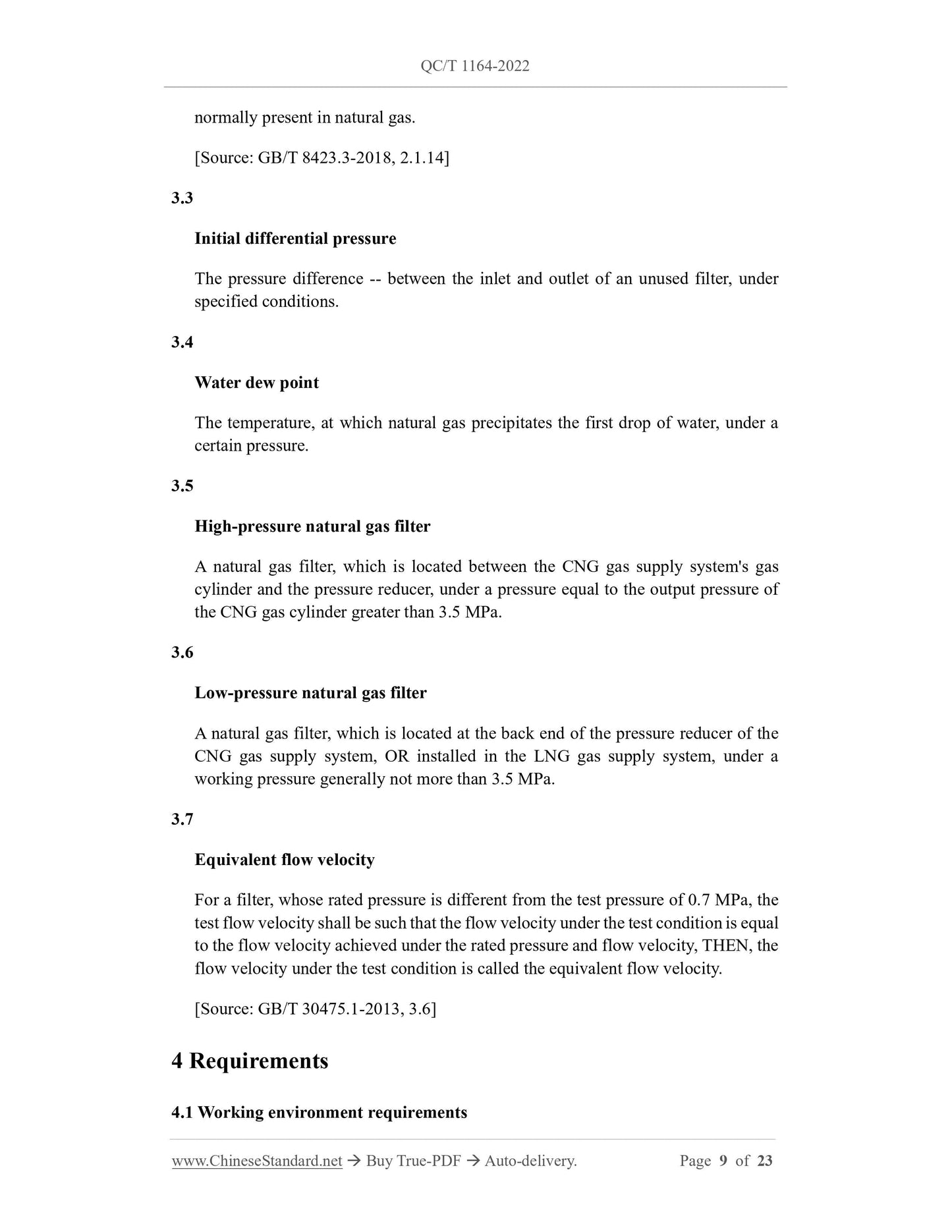
normally present in natural gas.
[Source: GB/T 8423.3-2018, 2.1.14]
3.3
Initial differential pressure
The pressure difference -- between the inlet and outlet of an unused filter, under
specified conditions.
3.4
Water dew point
The temperature, at which natural gas precipitates the first drop of water, under a
certain pressure.
3.5
High-pressure natural gas filter
A natural gas filter, which is located between the CNG gas supply system's gas
cylinder and the pressure reducer, under a pressure equal to the output pressure of
the CNG gas cylinder greater than 3.5 MPa.
3.6
Low-pressure natural gas filter
A natural gas filter, which is located at the back end of the pressure reducer of the
CNG gas supply system, OR installed in the LNG gas supply system, under a
working pressure generally not more than 3.5 MPa.
3.7
Equivalent flow velocity
For a filter, whose rated pressure is different from the test pressure of 0.7 MPa, the
test flow velocity shall be such that the flow velocity under the test condition is equal
to the flow velocity achieved under the rated pressure and flow velocity, THEN, the
flow velocity under the test condition is called the equivalent flow velocity.
[Source: GB/T 30475.1-2013, 3.6]
4 Requirements
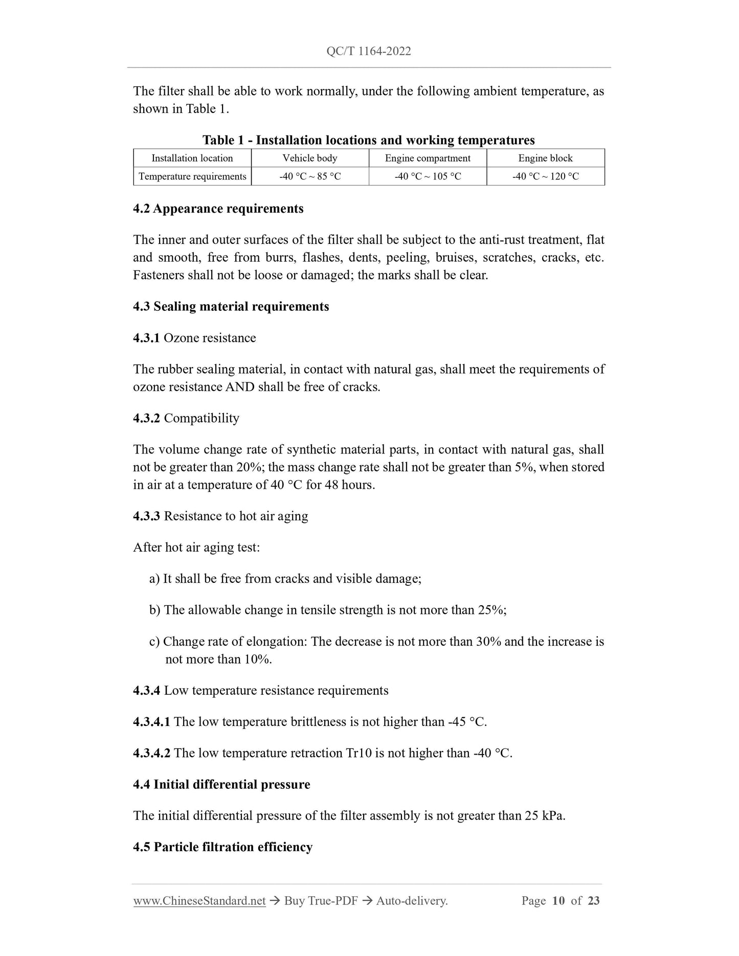
4.1 Working environment requirements
5.6.3 Test procedure
5.6.3.1 Prepare dry test ash with constant weight (drying temperature 120 °C ± 5 °C,
time 1 h) and electronic balance.
5.6.3.2 Use the electronic balance, which has the accuracy required by the standard, to
weigh the filter elements of the filter under test and the backup filter. Record their
masses as m1 and m1', respectively.
5.6.3.3 Install the weighed filter element into the filter under test and the backup filter,
respectively.
5.6.3.4 Confirm that valves 2 and 5 are closed. Slowly open valve 1. Adjust the pressure
reduction valve 3, to make pressure gauge 7 reach the test pressure. Adjust the flow
control valve 12, to make the reading of flow meter 11 reach the test value. Record the
initial pressure drop value, after stabilization.
5.6.3.5 Add the weighed ash into the ash-adding container 6. Then fully open the valves
2 and 5, in sequence. Then close the valves 5 and 2 in sequence after a few seconds.
Record the reading, after the reading of the differential pressure gauge 9 is stable.
5.6.3.6 Repeat step 5.6.3.5, until the reading of differential pressure gauge 9 reaches or
exceeds the net differential pressure. Add up the total amount of ash added at this time.
Record it as m.
5.6.3.7 Slowly close the valve 1. After the pressure gauge's reading drops to close to 0,
carefully take out the filter elements of the filter under test and the backup filter. Weigh
their masses. Record them as m2 and m2', respectively.
5.6.3.8 Use the abscissa as the amount of ash added, the pressure difference as the
ordinate, to draw the differential pressure characteristic curve of the tested filter element,
as shown in Figure 2.
5.6.3.9 Draw a straight line, using the cut-off pressure difference on the ordinate; the
product -- of the corresponding value on the abscissa corresponding to the intersection
point of the curve and (m2 - m1)/m -- is the dust holding capacity of the filter element.
5.6.3.10 Repeat the test of the filter element of the same specification. Take the average
value of 3 valid test results. Record it as the dirt holding capacity of the filter.
5.6.4 Judgment of test validity
5.6.4.1 The ratio -- of the mass change of the tested filter element TO the total amount
of ash added (m2 - m1)/m -- shall be within the range of 90% ~ 105%.
5.6.4.2 The ratio -- of the mass change of the backup filter element to the total ash
addition -- (m2' - m1')/m, shall meet the requirement of not more than 1%.
pressure source. Install an automatic valve and pressure [translator note: should be
pressure gauge], which has a pressure not less than 1.5 times and not more than 2 times
the test pressure in the pressure supply pipe. The pressure gauge is installed, between
the automatic valve and the test piece.
5.8.3.3 When under the test pressure, the test piece shall be immersed in the silicone oil,
to observe whether there are bubbles or detect the leakage:
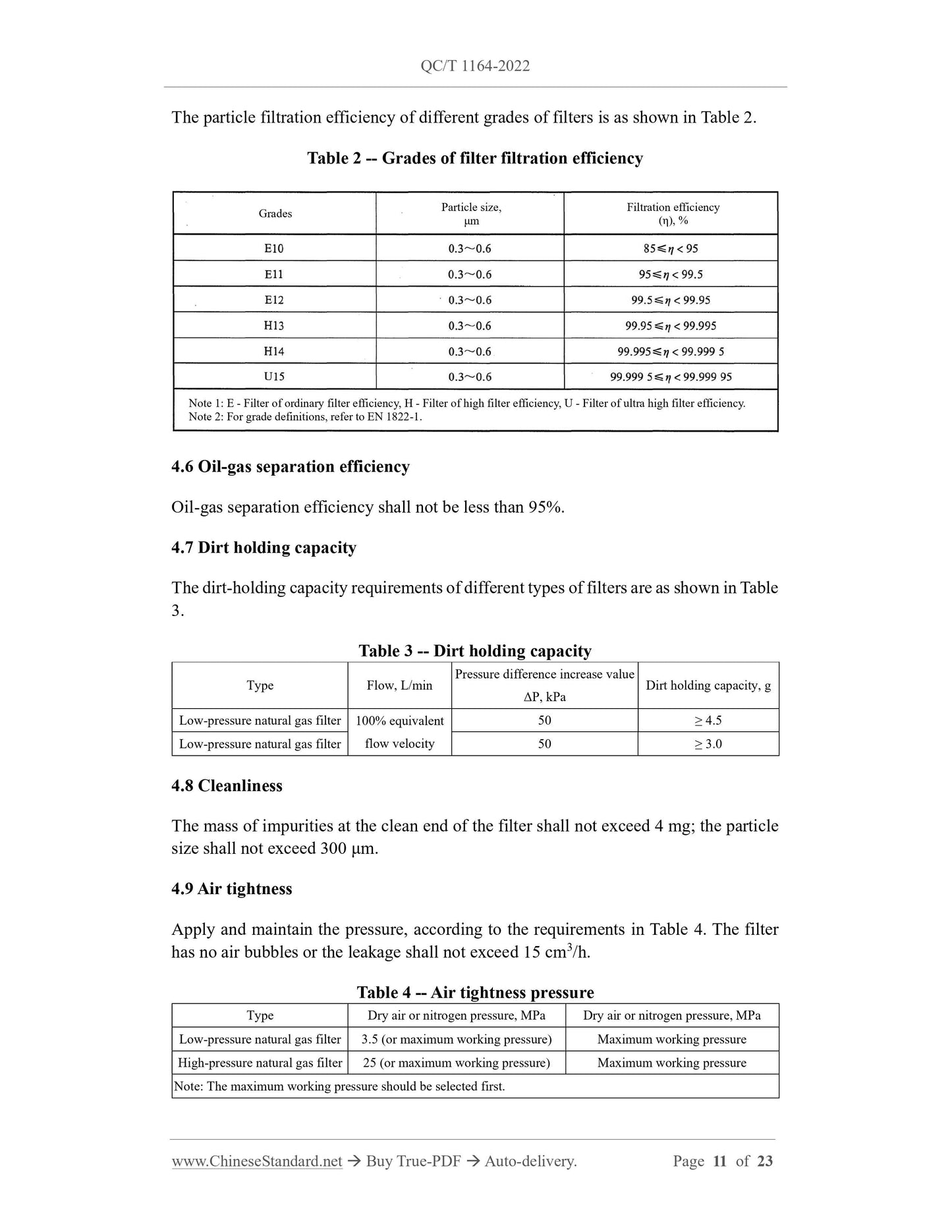
a) Room temperature test: Close the outlet of the filter. Place it at room temperature
and maximum working pressure for 8 hours. After 8 hours, start to observe
whether there are bubbles or detect leakage, for a duration of 2 minutes;
b) High temperature test: Close the outlet of the filter. Place it at the specified
maximum working temperature and maximum working pressure for 8 hours.
After 8 hours, start to observe whether there are bubbles or detect leakage, for a
duration of 2 minutes. During the whole process, the sample cannot leave the
specified ambient temperature;
c) Low temperature test: Close the outlet of the filter. Place it at the specified
minimum working temperature and maximum working pressure for 8 hours. After
8 hours, start to observe whether there are bubbles or detect leakage, for a duration
of 2 minutes. During the whole process, the sample cannot leave the specified
ambient temperature.
5.9 Overpressure strength test
5.9.1 Test medium
Use water or hydraulic oil.
5.9.2 Test procedure
5.9.2.1 The test sample is connected to the pressure source. The pressure relief valve
and pressure gauge shall be installed, in the pressure supply pipe, which is not less than
1.5 times and not more than 2 times the working pressure.
5.9.2.2 Open the pressure relief valve to exhaust. Close the pressure relief valve, after
the test liquid appears at the gas outlet.
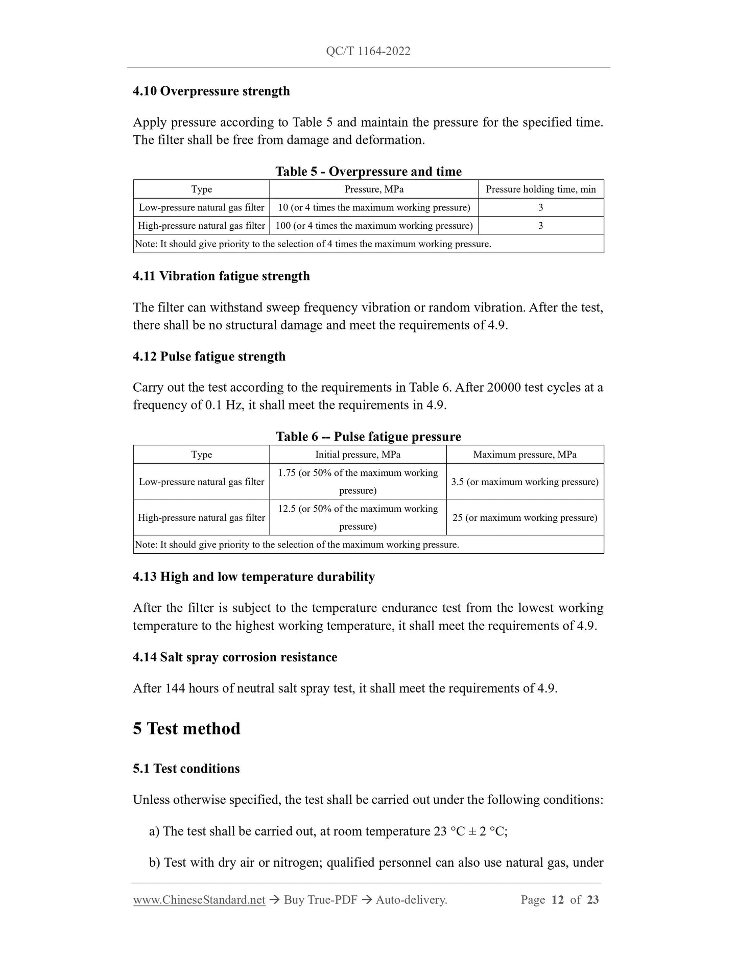
5.9.2.3 Turn on the pressure pump to increase the pressure. The pressure increase rate
shall be in accordance with the requirements in Table 9.
d) Filtration level;
e) Date of manufacture;
f) The maximum working pressure; indicate the maintenance and replacement
mileage of the filter element, as well as the safety matters to be paid attention to
when replacing the filter element;
g) The words "IN" and "OUT" or other letters, numbers and Chinese characters, that
can distinguish the air inlet and outlet, shall be clearly marked on the filter seat
near the inlet and outlet.
7.1.2 There shall be a traceability mark, on each filter element.
7.2 Packaging
7.2.1 When the filter product leaves the factory, a special packing box shall be used.
The marks on the packing box and the outside to prevent rain, moisture, pressure,
bumps shall comply with the provisions of GB/T 191 and GB/T 6388. On the packing
box, at least the following shall be marked:
a) Manufacturer's name, trademark, address;
b) Product model, name, quantity;
c) Production date and mass.
7.2.2 The following documents shall be attached into the packing box:
a) Product testing report, material report, performance report, etc.;
b) The qualification certificate signed or stamped by the inspector;
c) Product instruction manual.
7.3 Transportation
During the transportation of the product, it is necessary to prevent bumps, pressure, rain,
moisture; the gas inlet and outlet must be protected with dust caps.
7.4 Storage
The product shall be stored in a ventilated, dry and non-corrosive gas warehouse; it
shall not be squeezed by heavy objects.
QC/T 1164-2022
QC
AUTOMOBILE INDUSTRY STANDARD
OF THE PEOPLE’S REPUBLIC OF CHINA
ICS 43.060.40
CCS T 13
Natural gas filter for road vehicle
ISSUED ON: APRIL 08, 2022
IMPLEMENTED ON: OCTOBER 01, 2022
Issued by: Ministry of Industry and Information Technology of PRC
Table of Contents
Foreword ... 6
1 Scope ... 7
2 Normative references ... 7
3 Terms and definitions ... 8
4 Requirements ... 9
5 Test method ... 12
6 Inspection rules ... 20
7 Marking, packaging, transportation and storage ... 21
References ... 23
Natural gas filter for road vehicle
1 Scope
This document specifies the terms and definitions, classification, technical
requirements, test methods, inspection rules and signs, packaging, transportation,
storage related to natural gas filters for road vehicles (referred to as filters).
This document is applicable to filters that use natural gas as the working medium to
achieve particulate impurity filtration and liquid-gas separation, in the gas supply
system of automobiles.
2 Normative references
The contents of the following documents constitute the essential provisions of this
document through normative references in the text. Among them, for dated references,
only the version corresponding to the date is applicable to this document; for undated
references, the latest version (including all amendments) is applicable to this document.
GB/T 191 Packaging - Pictorial marking for handling of goods
GB/T 1682 Rubber, vulcanized - Determination of low-temperature brittleness -
Single test piece method
GB/T 1690 Rubber vulcanized or thermoplastic - Determination of the effect of
liquids
GB 18047 Compressed natural gas as vehicle fuel
GB/T 3512 Rubber, vulcanized or thermoplastic - Accelerated ageing and heat
resistance tests
GB/T 3821 Small and medium power internal combustion engines - Cleanliness
limits and measurements
GB 6388 Transport package shipping mark
GB/T 7762 Rubber, vulcanized or thermoplastic - Resistance to ozone cracking -
Static strain testing
GB/T 7758 Rubber, vulcanized - Determination of low-temperature characteristics
- Temperature-retraction procedure (TR test)
normally present in natural gas.
[Source: GB/T 8423.3-2018, 2.1.14]
3.3
Initial differential pressure
The pressure difference -- between the inlet and outlet of an unused filter, under
specified conditions.
3.4
Water dew point
The temperature, at which natural gas precipitates the first drop of water, under a
certain pressure.
3.5
High-pressure natural gas filter
A natural gas filter, which is located between the CNG gas supply system's gas
cylinder and the pressure reducer, under a pressure equal to the output pressure of
the CNG gas cylinder greater than 3.5 MPa.
3.6
Low-pressure natural gas filter
A natural gas filter, which is located at the back end of the pressure reducer of the
CNG gas supply system, OR installed in the LNG gas supply system, under a
working pressure generally not more than 3.5 MPa.
3.7
Equivalent flow velocity
For a filter, whose rated pressure is different from the test pressure of 0.7 MPa, the
test flow velocity shall be such that the flow velocity under the test condition is equal
to the flow velocity achieved under the rated pressure and flow velocity, THEN, the
flow velocity under the test condition is called the equivalent flow velocity.
[Source: GB/T 30475.1-2013, 3.6]
4 Requirements
4.1 Working environment requirements
5.6.3 Test procedure
5.6.3.1 Prepare dry test ash with constant weight (drying temperature 120 °C ± 5 °C,
time 1 h) and electronic balance.
5.6.3.2 Use the electronic balance, which has the accuracy required by the standard, to
weigh the filter elements of the filter under test and the backup filter. Record their
masses as m1 and m1', respectively.
5.6.3.3 Install the weighed filter element into the filter under test and the backup filter,
respectively.
5.6.3.4 Confirm that valves 2 and 5 are closed. Slowly open valve 1. Adjust the pressure
reduction valve 3, to make pressure gauge 7 reach the test pressure. Adjust the flow
control valve 12, to make the reading of flow meter 11 reach the test value. Record the
initial pressure drop value, after stabilization.
5.6.3.5 Add the weighed ash into the ash-adding container 6. Then fully open the valves
2 and 5, in sequence. Then close the valves 5 and 2 in sequence after a few seconds.
Record the reading, after the reading of the differential pres...
Share
