1
/
of
7
PayPal, credit cards. Download editable-PDF & invoice in 1 second!
QC/T 29082-2019 English PDF (QCT29082-2019)
QC/T 29082-2019 English PDF (QCT29082-2019)
Regular price
$350.00 USD
Regular price
Sale price
$350.00 USD
Unit price
/
per
Shipping calculated at checkout.
Couldn't load pickup availability
Delivery: 3 seconds. Download true-PDF + Invoice.
Get QUOTATION in 1-minute: Click QC/T 29082-2019
Historical versions: QC/T 29082-2019
Preview True-PDF (Reload/Scroll if blank)
QC/T 29082-2019: Specifications and bench test methods of automobile propeller shaft assembly
QC/T 29082-2019
QC
AUTOMOTIVE INDUSTRY STANDARD
OF THE PEOPLE’S REPUBLIC OF CHINA
ICS 43.040.50
T 21
Replacing QC/T 29082-1992, QC/T 523-1999
Specifications and Bench Test Methods of Automobile
Propeller Shaft Assembly
ISSUED ON: NOVEMBER 11, 2019
IMPLEMENTED ON: APRIL 01, 2020
Issued by: Ministry of Industry and Information Technology of PRC
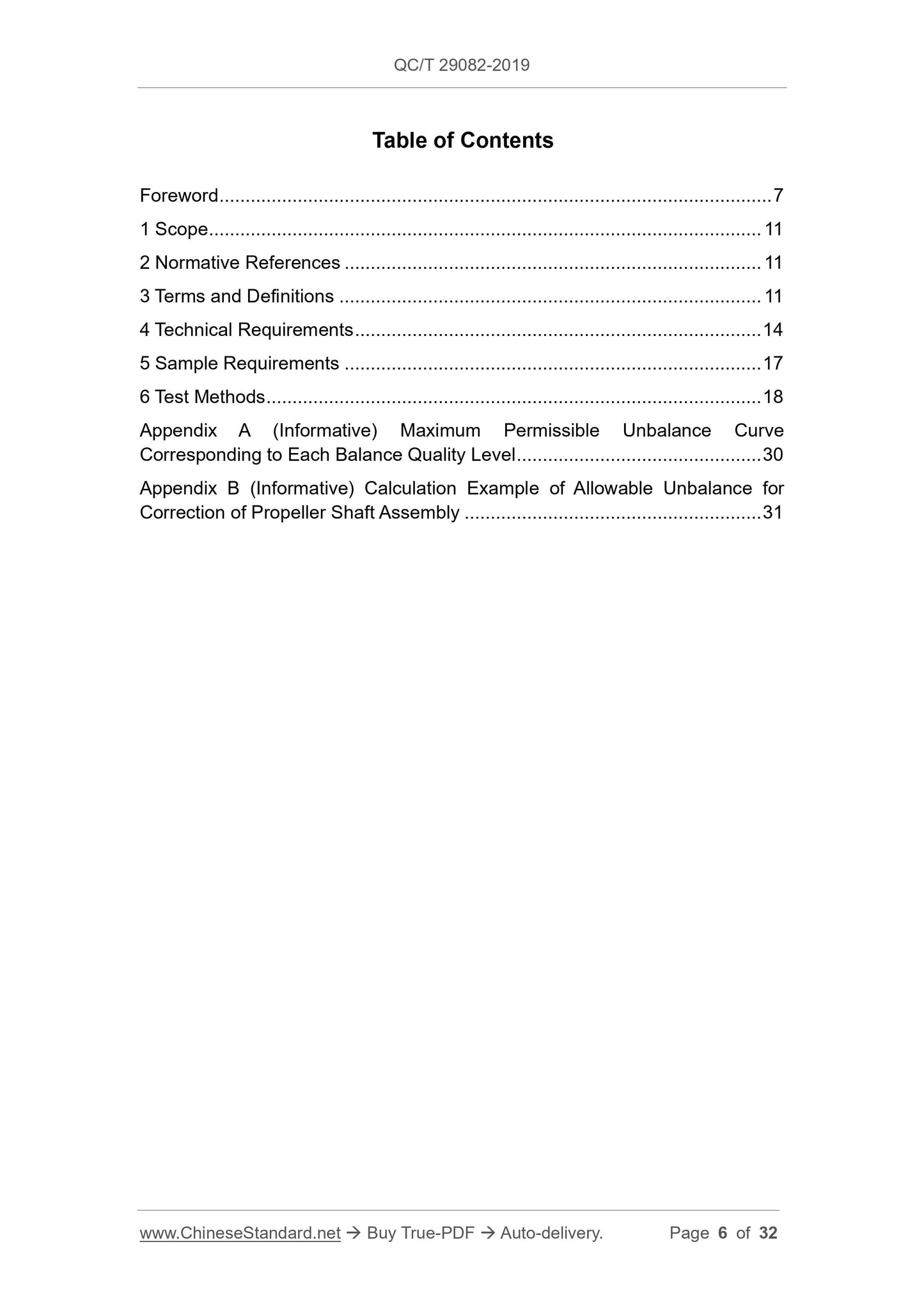
Table of Contents
Foreword ... 7
1 Scope ... 11
2 Normative References ... 11
3 Terms and Definitions ... 11
4 Technical Requirements ... 14
5 Sample Requirements ... 17
6 Test Methods ... 18
Appendix A (Informative) Maximum Permissible Unbalance Curve
Corresponding to Each Balance Quality Level ... 30
Appendix B (Informative) Calculation Example of Allowable Unbalance for
Correction of Propeller Shaft Assembly ... 31
Specifications and Bench Test Methods of Automobile
Propeller Shaft Assembly
1 Scope
This Standard specifies the technical conditions and bench test methods for the cross
shaft universal joint propeller shaft assembly (hereinafter referred to as the propeller
shaft assembly).
This Standard is applicable to the propeller shaft assembly for light, medium and heavy
vehicles and their refitted vehicles; the propeller shaft assembly for miniature vehicles
and their refitted vehicle can be used as a reference.
2 Normative References
The following documents are essential to the application of this document. For the
dated documents, only the versions with the dates indicated are applicable to this
document; for the undated documents, only the latest version (including all the
amendments) is applicable to this document.
GB/T 5671 General Purpose Lithium Lubricating Grease for Automobile
GB/T 9239.1-2006 Mechanical Vibration - Balance Quality Requirements for
Rotors in a Constant (Rigid) State - Part 1: Specification and Verification of
Balance Tolerances
GB/T 9239.14 Mechanical Vibration - Rotor Balancing - Part 14: Procedures for
Assessing Balance Errors
JB/T 8925 Rolling Bearings - Automobile U-Joint Cross Assembly – Specifications
QC/T 484-1999 Automobile Paint Coating
QC/T 518 Tightening Torque for Automotive Threaded Fasteners
YB/T 5209 Electric-Welded Steel Tubes for Cardan Shaft
3 Terms and Definitions
3.1 Propeller shaft assembly
4 Technical Requirements
4.1 General technical requirements
4.1.1 The propeller shaft assembly shall be manufactured in accordance with the
drawings and technical documents approved by the prescribed procedures.
4.1.2 The universal joint cross shaft assembly shall comply with the relevant provisions
of JB/T 8925.
4.1.3 Electric-welded steel pipes for propeller shaft assembly shall refer to the relevant
provisions of YB/T 5209.
4.1.4 The parts used for assembly shall be cleaned before assembly.
4.1.5 The appearance of the propeller shaft assembly and the machined surface of the
parts shall not have defects such as burrs, bumps, rust, creases, distortions, cracks,
etc.
4.1.6 The welding quality of the welded joints of the propeller shaft assembly and shaft
pipe shall be reliable; the size of the welding seam shall meet the requirements of the
drawing; the appearance of the welding seam shall be smooth and uninterrupted; and
there shall be no defects such as false welding, slag inclusion, etc.
4.1.7 When assembling, it shall not be missed or wrongly installed; the connecting
fasteners shall be firm and reliable; and the tightening torque shall comply with the
provisions of QC/T 518.
4.1.8 For the universal joint of pressure plate structure; the protruding part of its back
plate shall be embedded in the groove of the outer end face of the bearing bowl; and
the fixed locking piece shall be locked with the fastening bolts on the pressure plate.
For the universal joint with snap ring structure, the snap ring shall be fully embedded
in the ear hole grove or the outer groove of the bearing bowl.
4.1.9 When assembling the propeller shaft assembly, if there is a grease nipple on the
cross shaft, it shall be on the same side as the grease nipple on the spline pair.
4.1.10 The universal joints at both ends of the propeller shaft assembly shall be on the
specified phase plane; and the deviation shall be no greater than 3°.
4.1.11 After the sliding spline pair is assembled, it shall be able to slide axially within
the working length range required by the design, and there shall be no jamming
phenomenon.
4.1.12 After the propeller shaft assembly is assembled, when it rotates along the
conical surface movement trajectory formed by the angle of the universal joint in the
forward and reverse directions, the universal joint shall work smoothly, and there shall
be no jamming phenomenon. The angle of the universal joint shall meet the design
requirements.
4.1.13 After the propeller shaft assembly is assembled, 100% of the residual
unbalance test shall be done. Weld the balance sheet at both ends of the propeller
shaft assembly to correct the unbalance. The balance sheet shall be welded firmly,
with no more than 3 pieces at each end. The residual unbalance of the propeller shaft
assembly for highway vehicles shall be no lower than the G16 balance quality level
specified in GB/T 9239.1-2006; and the residual unbalance of the propeller shaft
assembly for off-highway vehicles shall be no lower than the G40 balance quality level
specified in GB/T 9239.1-2006 (see Appendixes A and B).
4.1.14 The balance error shall be checked in accordance with the provisions of GB/T
9239.14. After the dynamic balance test is completed, the phase of the propeller shaft
assembly shall be rotated 180° and re-installed for double balance detection; and the
measured value shall not exceed 1.5 times the allowable value.
4.1.15 The non-assembled surface of the propeller shaft assembly shall be painted
according to the TQ6 coating specification in QC/T 484-1999 or user requirements.
4.1.16 The assembly surface of the propeller shaft assembly shall be rust-proof.
4.1.17 The propeller shaft assembly shall be marked with a permanent assembly mark
and identification code at an obvious assembly location.
4.1.18 Before the propeller shaft assembly leaves the factory, all lubricating parts shall
be filled with lithium-based grease for automobiles in accordance with the provisions
of GB/T 5671; and other greases not lower than the above-mentioned standards can
also be filled.
4.1.19 After the propeller shaft assembly is assembled, the intermediate support
bearing shall rotate flexibly.
4.1.20 It is recommended that the universal joint angle of the propeller shaft assembly
shall not exceed 5° when the vehicle is fully loaded.
4.2 Performance requirements
4.2.1 Static runout
It shall meet the requirements of product drawing technical conditions.
4.2.2 Torsional clearance
It shall meet the requirements of product drawing technical conditions.
4.2.3 Residual unbalance
It shall meet the requirements of product drawing technical conditions.
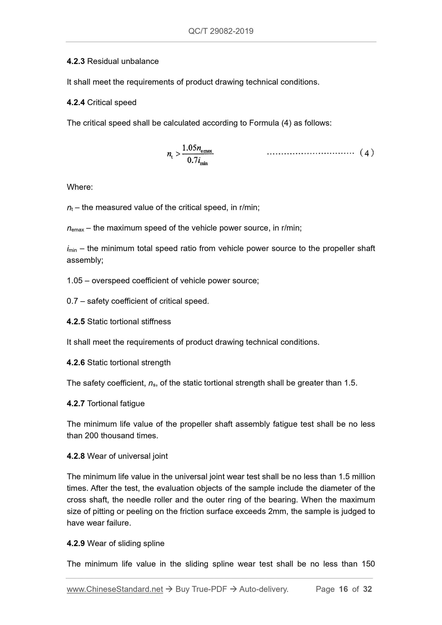
4.2.4 Critical speed
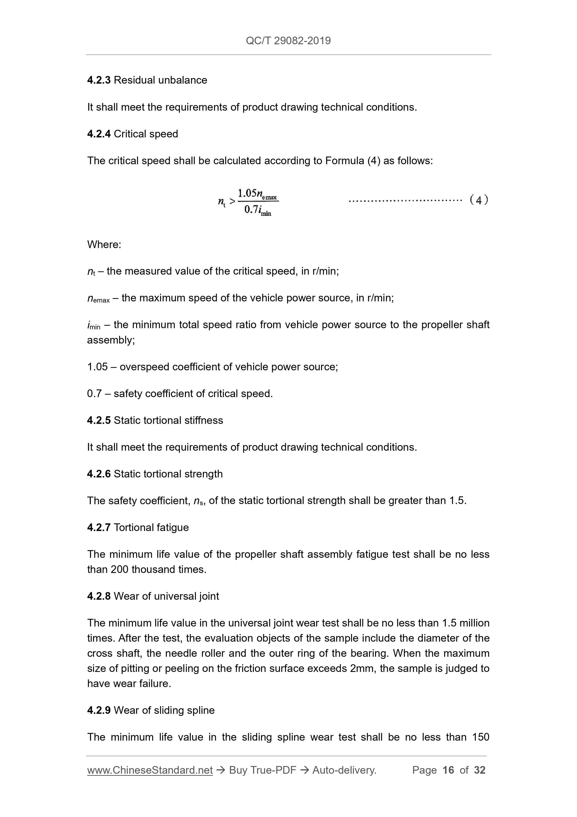
The critical speed shall be calculated according to Formula (4) as follows:
Where:
nt – the measured value of the critical speed, in r/min;
nemax – the maximum speed of the vehicle power source, in r/min;
imin – the minimum total speed ratio from vehicle power source to the propeller shaft
assembly;
1.05 – overspeed coefficient of vehicle power source;
0.7 – safety coefficient of critical speed.
4.2.5 Static tortional stiffness
It shall meet the requir...
Share
