1
/
of
12
PayPal, credit cards. Download editable-PDF & invoice in 1 second!
QC/T 324-2000 English PDF (QC/T324-2000)
QC/T 324-2000 English PDF (QC/T324-2000)
Regular price
$180.00 USD
Regular price
Sale price
$180.00 USD
Unit price
/
per
Shipping calculated at checkout.
Couldn't load pickup availability
Delivery: 3 seconds. Download true-PDF + Invoice.
Get QUOTATION in 1-minute: Click QC/T 324-2000
Historical versions: QC/T 324-2000
Preview True-PDF (Reload/Scroll if blank)
QC/T 324-2000: Automotive fuel air heater
QC/T 324-2000
QC
AUTOMOBILE INDUSTRY STANDARD
OF THE PEOPLE’S REPUBLIC OF CHINA
Replacing QC/T 324-1999, QC/T 325-1999
Automotive fuel air heater
ISSUED ON. JANUARY 19, 2000
IMPLEMENTED ON. JULY 1, 2000
Issued by. National Mechanical Industry Bureau
Table of Contents
Foreword ... 3
1 Scope ... 4
2 Reference standards ... 4
3 Definitions ... 4
4 Technical requirements ... 5
5 Test methods ... 8
6 Inspection rules ... 13
7 Marking, packaging, transportation, and storage ... 14
Appendix A (Normative) Calculation equations for heater tests ... 16
Appendix B (Normative) Heater heat release test record sheet ... 19
Automotive fuel air heater
1 Scope
This Standard specifies the technical requirements, test methods, and
inspection rules, etc. for centrifugal atomized automotive fuel air heater.
This Standard applies to the centrifugal atomized fuel air heater for automobiles
(hereinafter knowns as heater for short). Other forms of fuel air heaters can
refer to it for implementation.
2 Reference standards
The provisions contained in the following standards, by reference in this
Standard, constitute provisions of this Standard. At the time of publication of the
standard, the shown editions are valid. All standards will be revised. Parties
which use this Standard shall discuss the possibility of using the latest edition
of the following standards.
GB 252-1994 Light diesel fuels
GB 1236-1985 Test methods of aerodynamic performance for fans
GB 1859-1989 Determination of sound power levels of internal combustion
engines noise - Quasi-engineering method
QC/T 413-1999 Automotive electrical equipment basic technical conditions
QC/T 484-1999 Car paint coating
QC/T 625-1999 Automotive coating and chemical treatment layer
QC/T 29092-1992 Technical specifications for automotive heater motor
3 Definitions
This Standard uses the following definitions.
3.1 Heater
A device which uses fuel oil as fuel and air as heat exchange medium for
automobile occupant heating, windscreen defrosting, and heating of engine
cooling water and oil. It includes atomizer, combustor, heat exchanger, oil pump,
motor, and other components.
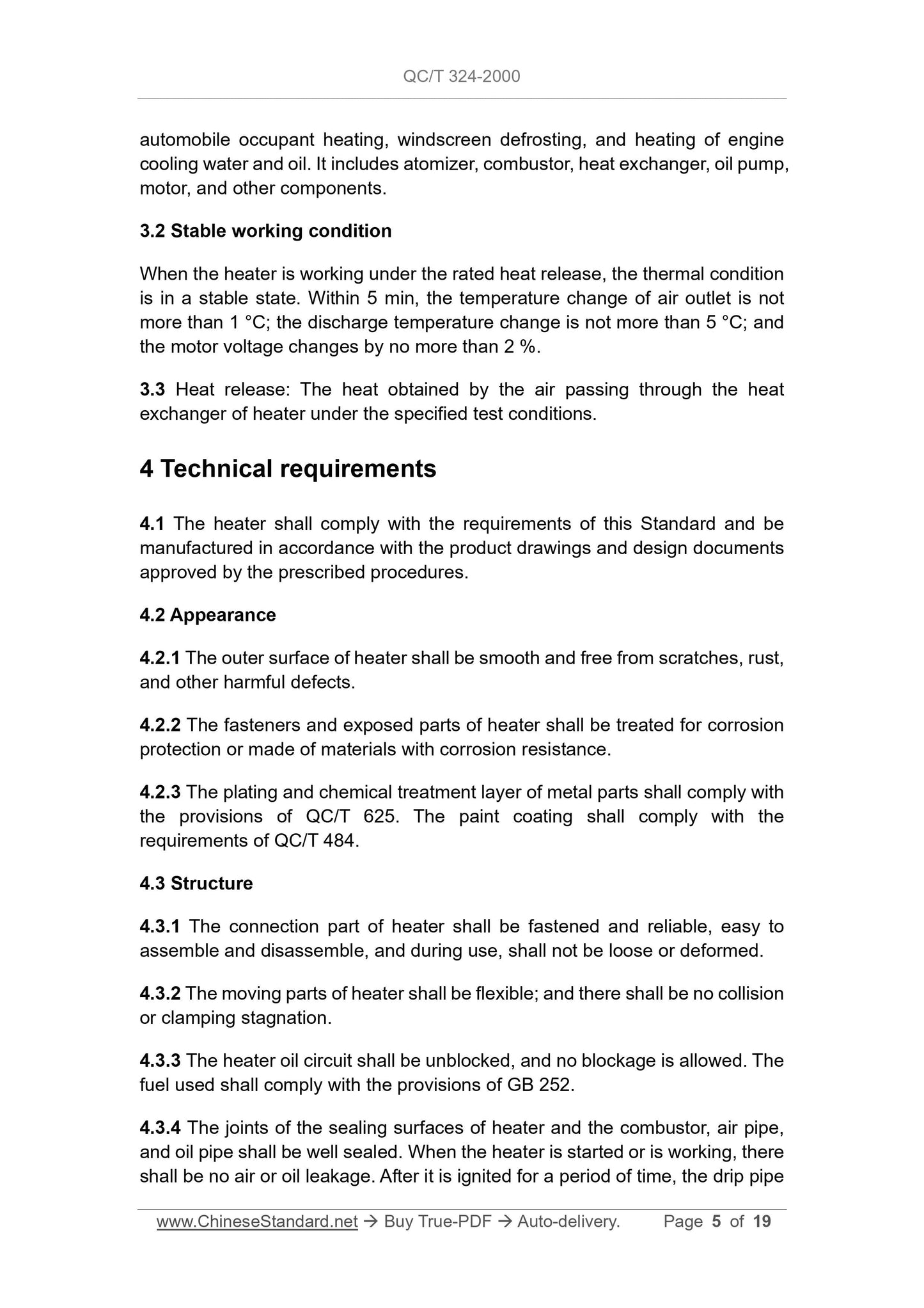
3.2 Stable working condition
When the heater is working under the rated heat release, the thermal condition
is in a stable state. Within 5 min, the temperature change of air outlet is not
more than 1 °C; the discharge temperature change is not more than 5 °C; and
the motor voltage changes by no more than 2 %.
3.3 Heat release. The heat obtained by the air passing through the heat
exchanger of heater under the specified test conditions.
4 Technical requirements
4.1 The heater shall comply with the requirements of this Standard and be
manufactured in accordance with the product drawings and design documents
approved by the prescribed procedures.
4.2 Appearance
4.2.1 The outer surface of heater shall be smooth and free from scratches, rust,
and other harmful defects.
4.2.2 The fasteners and exposed parts of heater shall be treated for corrosion
protection or made of materials with corrosion resistance.
4.2.3 The plating and chemical treatment layer of metal parts shall comply with
the provisions of QC/T 625. The paint coating shall comply with the
requirements of QC/T 484.
4.3 Structure
4.3.1 The connection part of heater shall be fastened and reliable, easy to
assemble and disassemble, and during use, shall not be loose or deformed.
4.3.2 The moving parts of heater shall be flexible; and there shall be no collision
or clamping stagnation.
4.3.3 The heater oil circuit shall be unblocked, and no blockage is allowed. The
fuel used shall comply with the provisions of GB 252.
4.3.4 The joints of the sealing surfaces of heater and the combustor, air pipe,
and oil pipe shall be well sealed. When the heater is started or is working, there
shall be no air or oil leakage. After it is ignited for a period of time, the drip pipe
5 Test methods
5.1 Test conditions
Unless otherwise specified, heaters are generally tested under the following
conditions.
5.1.1 Test voltage
When the nominal voltage is 12 V, the test voltage is (13.5±0.3) V. When the
nominal voltage is 24 V, the test voltage is (27.0±0.6) V.
5.1.2 Atmospheric pressure. 86 kPa~106 kPa.
5.1.3 The heater is mounted on the bench. Its axis must be horizontal and shall
not be disturbed by natural wind. After installing the air duct, there shall be no
obstacles in the surrounding space with a distance of 3 D (D is the diameter of
the air duct) away from the center of air inlet, outlet, and exhaust port end faces.
The axis shall be no less than 1 m from the ground.
5.1.4 The measurement of each parameter must be carried out under stable
working condition of heater.
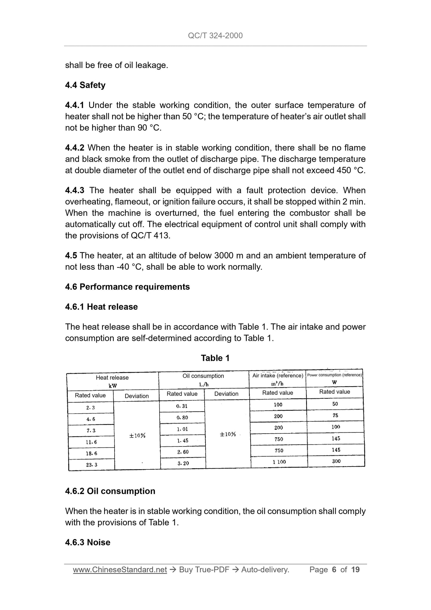
5.2 Heat release test
5.2.1 Test equipment
a) Special test bench;
b) Pitot tube;
c) Micromanometer. minimum division value 1.0 Pa;
d) Thermometer. minimum scale value 0.1 °C;
e) Air duct. SEE 5.2.2 for the requirements.
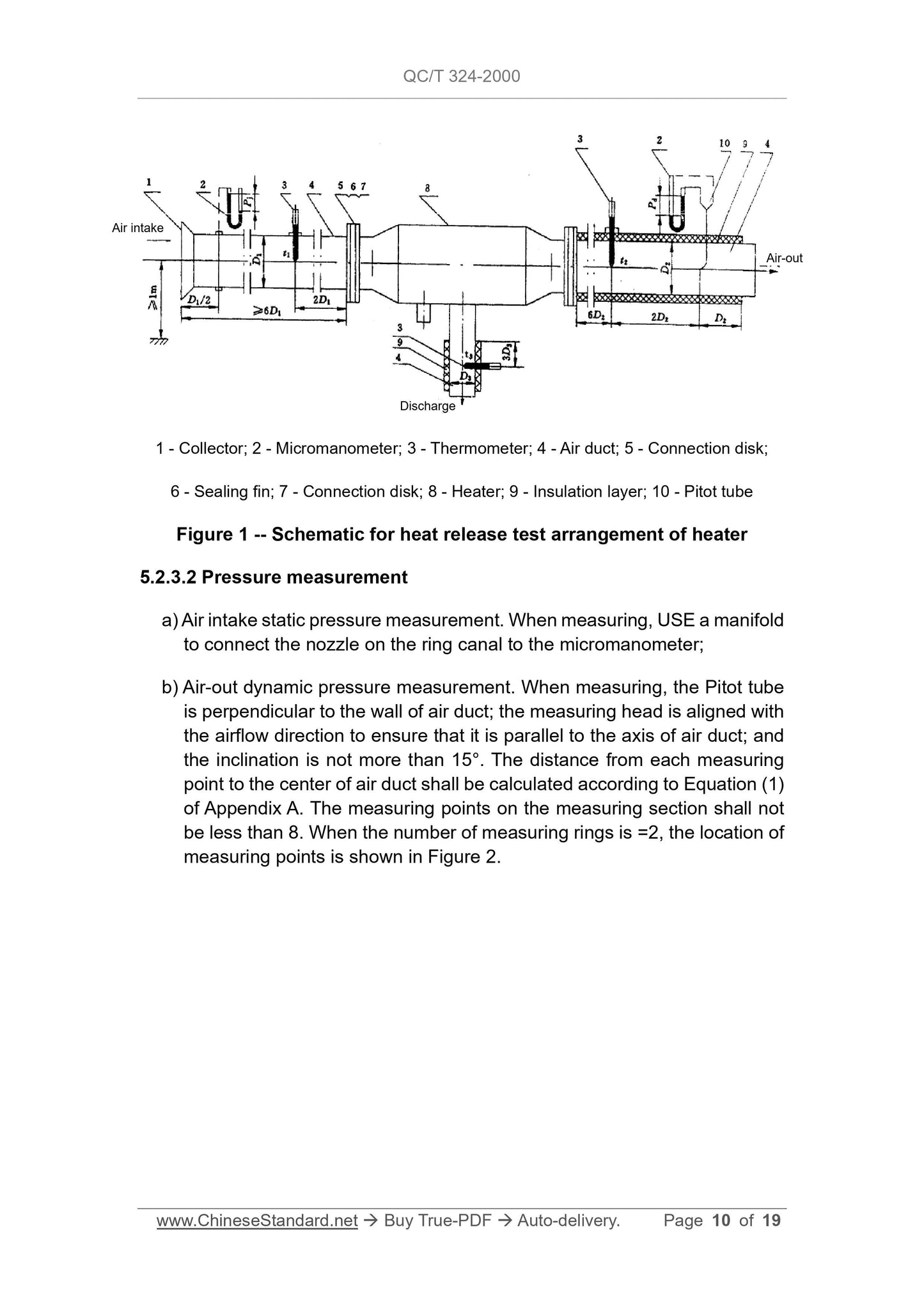
The arrangement of heat release test is shown in Figure 1.
5.2.2 The air duct shall meet the following requirements.
a) The diameter of air duct shall remain constant throughout the length and
be equal to the diameter of the inlet and outlet of heater as much as
possible. If not equal, the taper joint shall be used for connection. The
taper joint shall meet the requirements of Chapter 5 of GB 1236;
b) The air duct for air-out and discharge must be insulated. The insulation
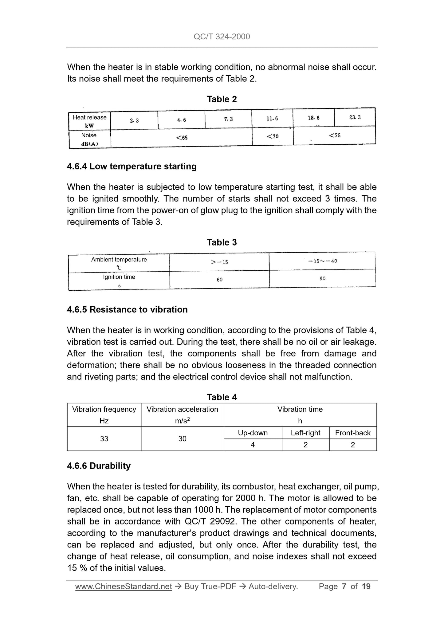
5.4 Noise test
The heater is arranged according to the normal working position. The noise
measurement is carried out in accordance with the relevant provisions of GB
1859. The measurement results shall comply with the provisions of 4.6.3.
5.5 Low temperature starting test
5.5.1 Test conditions
a) The test shall be carried out separately in the following temperature
ranges.
(-15±2) °C
(-30±2) °C
(-40±2) °C
b) If there is no low temperature chamber, it is allowed to be carried out in
cold regions, but the temperature deviation is extended to ±5 °C.
5.5.2 Test procedures
a) PLACE the heater and fuel oil in a low temperature chamber or cold region,
LEAVE it for 10 h in a non-working condition; and then at the same
temperature, PERFORM a low temperature starting test;
b) The test results shall be in accordance with the provisions of 4.6.4.
5.6 Test of resistance to vibration
5.6.1 Test equipment
Vibration test bench.
5.6.2 Test procedures
a) The heater, according to the use requirements during working, is installed
on the vibration test bench. The test is conducted according to the
requirements of Table 4. During the vibration, PAY attention to the
abnormality of the oil circuit, circuit, mechanical parts, and working
conditions of heater; and FILL in the record. In the event of a fault, it is
allowed to stop the vibration. After troubleshooting, the test is continued;
b) During the vibration in the front-back and up-down directions, ignition test
is performed once respectively;
6.2.1 In any of the following cases, the manufacturer shall carry out type
inspection.
a) When the new product is finalized;
b) When the product design, process, and materials are greatly changed;
c) When the production resumes after one year of production shutdown;
d) Products produced in batches or in bulk, not less than once a year;
e) When the national quality supervision and inspection agency pr...
Get QUOTATION in 1-minute: Click QC/T 324-2000
Historical versions: QC/T 324-2000
Preview True-PDF (Reload/Scroll if blank)
QC/T 324-2000: Automotive fuel air heater
QC/T 324-2000
QC
AUTOMOBILE INDUSTRY STANDARD
OF THE PEOPLE’S REPUBLIC OF CHINA
Replacing QC/T 324-1999, QC/T 325-1999
Automotive fuel air heater
ISSUED ON. JANUARY 19, 2000
IMPLEMENTED ON. JULY 1, 2000
Issued by. National Mechanical Industry Bureau
Table of Contents
Foreword ... 3
1 Scope ... 4
2 Reference standards ... 4
3 Definitions ... 4
4 Technical requirements ... 5
5 Test methods ... 8
6 Inspection rules ... 13
7 Marking, packaging, transportation, and storage ... 14
Appendix A (Normative) Calculation equations for heater tests ... 16
Appendix B (Normative) Heater heat release test record sheet ... 19
Automotive fuel air heater
1 Scope
This Standard specifies the technical requirements, test methods, and
inspection rules, etc. for centrifugal atomized automotive fuel air heater.
This Standard applies to the centrifugal atomized fuel air heater for automobiles
(hereinafter knowns as heater for short). Other forms of fuel air heaters can
refer to it for implementation.
2 Reference standards
The provisions contained in the following standards, by reference in this
Standard, constitute provisions of this Standard. At the time of publication of the
standard, the shown editions are valid. All standards will be revised. Parties
which use this Standard shall discuss the possibility of using the latest edition
of the following standards.
GB 252-1994 Light diesel fuels
GB 1236-1985 Test methods of aerodynamic performance for fans
GB 1859-1989 Determination of sound power levels of internal combustion
engines noise - Quasi-engineering method
QC/T 413-1999 Automotive electrical equipment basic technical conditions
QC/T 484-1999 Car paint coating
QC/T 625-1999 Automotive coating and chemical treatment layer
QC/T 29092-1992 Technical specifications for automotive heater motor
3 Definitions
This Standard uses the following definitions.
3.1 Heater
A device which uses fuel oil as fuel and air as heat exchange medium for
automobile occupant heating, windscreen defrosting, and heating of engine
cooling water and oil. It includes atomizer, combustor, heat exchanger, oil pump,
motor, and other components.
3.2 Stable working condition
When the heater is working under the rated heat release, the thermal condition
is in a stable state. Within 5 min, the temperature change of air outlet is not
more than 1 °C; the discharge temperature change is not more than 5 °C; and
the motor voltage changes by no more than 2 %.
3.3 Heat release. The heat obtained by the air passing through the heat
exchanger of heater under the specified test conditions.
4 Technical requirements
4.1 The heater shall comply with the requirements of this Standard and be
manufactured in accordance with the product drawings and design documents
approved by the prescribed procedures.
4.2 Appearance
4.2.1 The outer surface of heater shall be smooth and free from scratches, rust,
and other harmful defects.
4.2.2 The fasteners and exposed parts of heater shall be treated for corrosion
protection or made of materials with corrosion resistance.
4.2.3 The plating and chemical treatment layer of metal parts shall comply with
the provisions of QC/T 625. The paint coating shall comply with the
requirements of QC/T 484.
4.3 Structure
4.3.1 The connection part of heater shall be fastened and reliable, easy to
assemble and disassemble, and during use, shall not be loose or deformed.
4.3.2 The moving parts of heater shall be flexible; and there shall be no collision
or clamping stagnation.
4.3.3 The heater oil circuit shall be unblocked, and no blockage is allowed. The
fuel used shall comply with the provisions of GB 252.
4.3.4 The joints of the sealing surfaces of heater and the combustor, air pipe,
and oil pipe shall be well sealed. When the heater is started or is working, there
shall be no air or oil leakage. After it is ignited for a period of time, the drip pipe
5 Test methods
5.1 Test conditions
Unless otherwise specified, heaters are generally tested under the following
conditions.
5.1.1 Test voltage
When the nominal voltage is 12 V, the test voltage is (13.5±0.3) V. When the
nominal voltage is 24 V, the test voltage is (27.0±0.6) V.
5.1.2 Atmospheric pressure. 86 kPa~106 kPa.
5.1.3 The heater is mounted on the bench. Its axis must be horizontal and shall
not be disturbed by natural wind. After installing the air duct, there shall be no
obstacles in the surrounding space with a distance of 3 D (D is the diameter of
the air duct) away from the center of air inlet, outlet, and exhaust port end faces.
The axis shall be no less than 1 m from the ground.
5.1.4 The measurement of each parameter must be carried out under stable
working condition of heater.
5.2 Heat release test
5.2.1 Test equipment
a) Special test bench;
b) Pitot tube;
c) Micromanometer. minimum division value 1.0 Pa;
d) Thermometer. minimum scale value 0.1 °C;
e) Air duct. SEE 5.2.2 for the requirements.
The arrangement of heat release test is shown in Figure 1.
5.2.2 The air duct shall meet the following requirements.
a) The diameter of air duct shall remain constant throughout the length and
be equal to the diameter of the inlet and outlet of heater as much as
possible. If not equal, the taper joint shall be used for connection. The
taper joint shall meet the requirements of Chapter 5 of GB 1236;
b) The air duct for air-out and discharge must be insulated. The insulation
5.4 Noise test
The heater is arranged according to the normal working position. The noise
measurement is carried out in accordance with the relevant provisions of GB
1859. The measurement results shall comply with the provisions of 4.6.3.
5.5 Low temperature starting test
5.5.1 Test conditions
a) The test shall be carried out separately in the following temperature
ranges.
(-15±2) °C
(-30±2) °C
(-40±2) °C
b) If there is no low temperature chamber, it is allowed to be carried out in
cold regions, but the temperature deviation is extended to ±5 °C.
5.5.2 Test procedures
a) PLACE the heater and fuel oil in a low temperature chamber or cold region,
LEAVE it for 10 h in a non-working condition; and then at the same
temperature, PERFORM a low temperature starting test;
b) The test results shall be in accordance with the provisions of 4.6.4.
5.6 Test of resistance to vibration
5.6.1 Test equipment
Vibration test bench.
5.6.2 Test procedures
a) The heater, according to the use requirements during working, is installed
on the vibration test bench. The test is conducted according to the
requirements of Table 4. During the vibration, PAY attention to the
abnormality of the oil circuit, circuit, mechanical parts, and working
conditions of heater; and FILL in the record. In the event of a fault, it is
allowed to stop the vibration. After troubleshooting, the test is continued;
b) During the vibration in the front-back and up-down directions, ignition test
is performed once respectively;
6.2.1 In any of the following cases, the manufacturer shall carry out type
inspection.
a) When the new product is finalized;
b) When the product design, process, and materials are greatly changed;
c) When the production resumes after one year of production shutdown;
d) Products produced in batches or in bulk, not less than once a year;
e) When the national quality supervision and inspection agency pr...
Share