1
/
of
12
PayPal, credit cards. Download editable-PDF and invoice in 1 second!
QC/T 35-2015 English PDF (QCT35-2015)
QC/T 35-2015 English PDF (QCT35-2015)
Regular price
$380.00 USD
Regular price
Sale price
$380.00 USD
Unit price
/
per
Shipping calculated at checkout.
Couldn't load pickup availability
Delivery: 3 seconds. Download true-PDF + Invoice.
Get QUOTATION in 1-minute: Click QC/T 35-2015
Historical versions: QC/T 35-2015
Preview True-PDF (Reload/Scroll if blank)
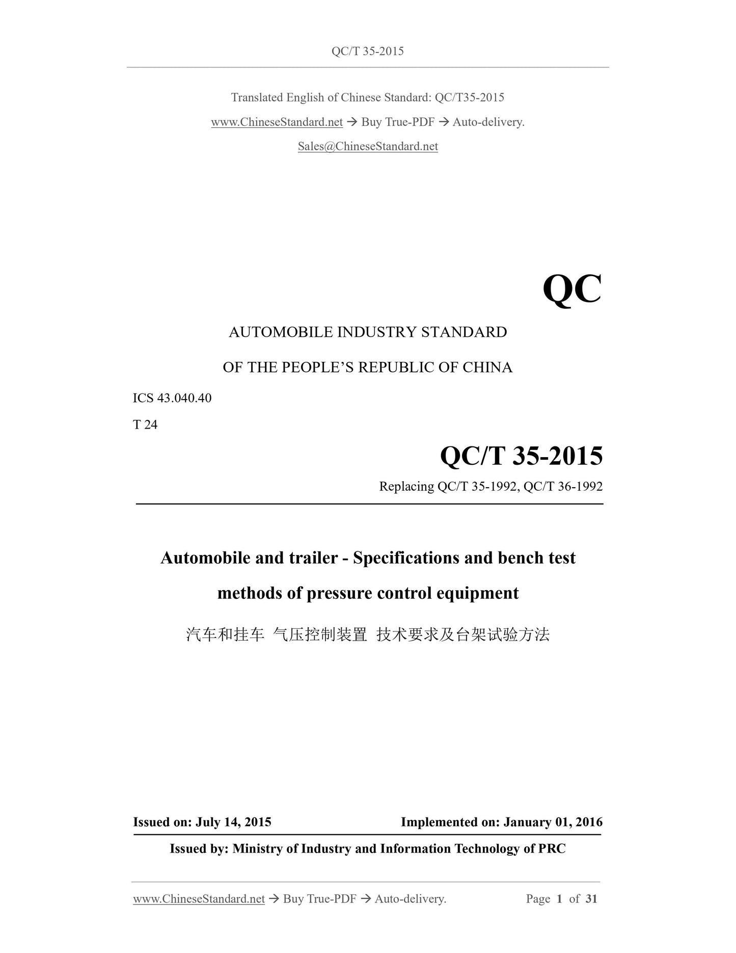
QC/T 35-2015: Automobile and trailer. Specifications and bench test methods of pressure control equipment
QC/T 35-2015
QC
AUTOMOBILE INDUSTRY STANDARD
ICS 43.040.40
T 24
Replacing QC/T 35-1992, QC/T 36-1992
Automobile and trailer - Specifications and bench test
methods of pressure control equipment
ISSUED ON. JULY 14, 2015
IMPLEMENTED ON. JANUARY 01, 2016
Issued by. Ministry of Industry and Information Technology of PRC
Table of Contents
Foreword... 6
1 Scope... 7
2 Normative references... 7
3 Terms and definitions... 7
4 Performance requirements... 9
5 Test-related requirements... 10
6 Test methods... 11
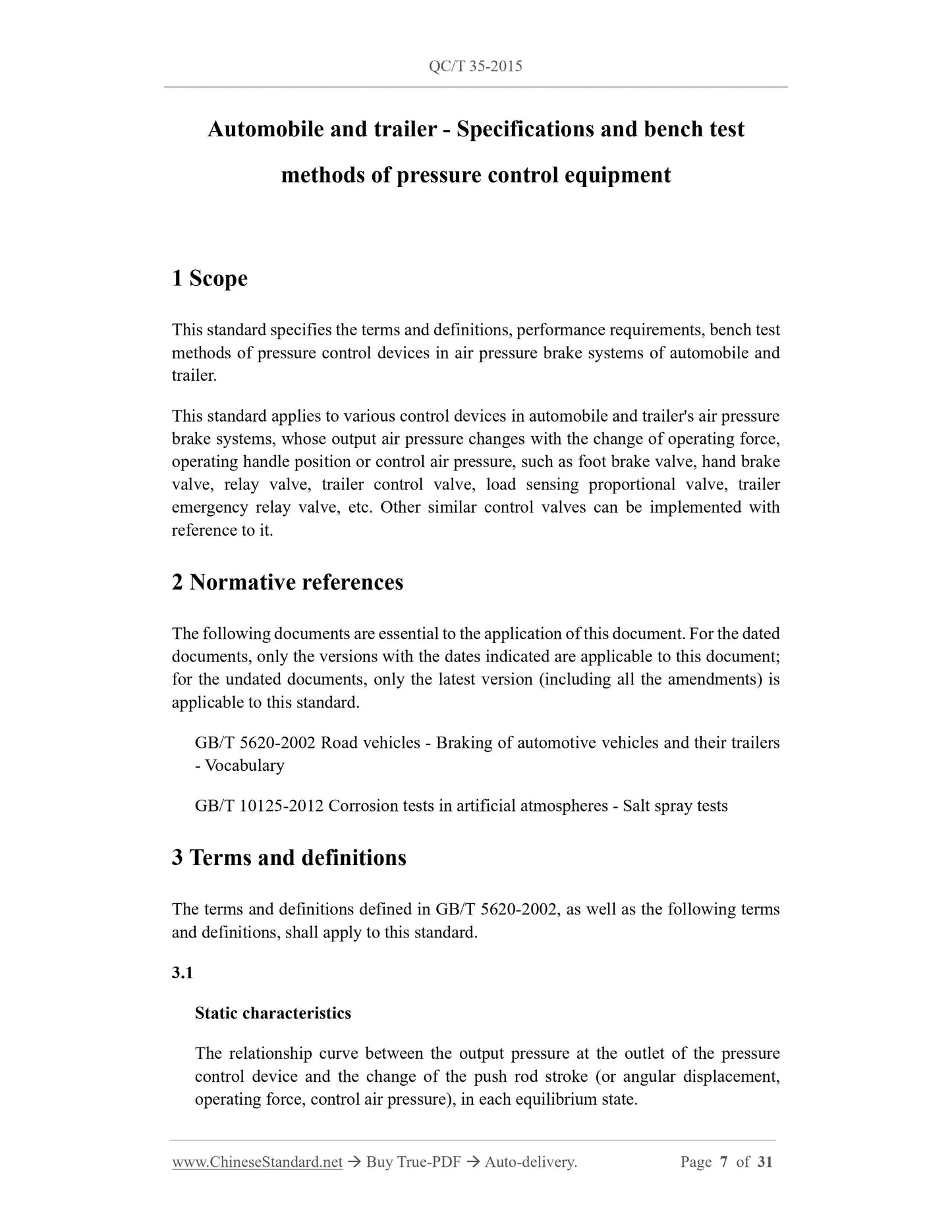
Automobile and trailer - Specifications and bench test
methods of pressure control equipment
1 Scope
This standard specifies the terms and definitions, performance requirements, bench test
methods of pressure control devices in air pressure brake systems of automobile and
trailer.
This standard applies to various control devices in automobile and trailer's air pressure
brake systems, whose output air pressure changes with the change of operating force,
operating handle position or control air pressure, such as foot brake valve, hand brake
valve, relay valve, trailer control valve, load sensing proportional valve, trailer
emergency relay valve, etc. Other similar control valves can be implemented with
reference to it.
2 Normative references
The following documents are essential to the application of this document. For the dated
documents, only the versions with the dates indicated are applicable to this document;
for the undated documents, only the latest version (including all the amendments) is
applicable to this standard.
GB/T 5620-2002 Road vehicles - Braking of automotive vehicles and their trailers
- Vocabulary
GB/T 10125-2012 Corrosion tests in artificial atmospheres - Salt spray tests
3 Terms and definitions
The terms and definitions defined in GB/T 5620-2002, as well as the following terms
and definitions, shall apply to this standard.
3.1
Static characteristics
The relationship curve between the output pressure at the outlet of the pressure
control device and the change of the push rod stroke (or angular displacement,
operating force, control air pressure), in each equilibrium state.
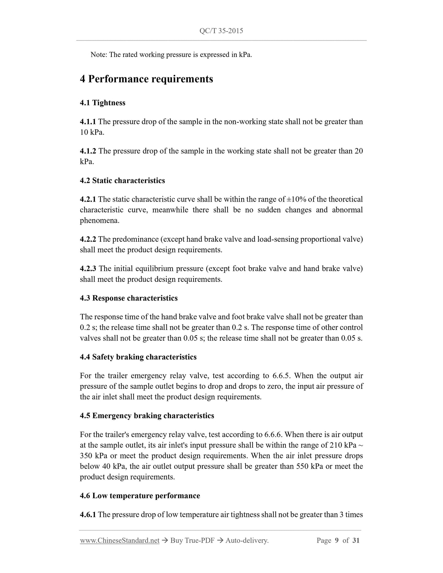
Note. The rated working pressure is expressed in kPa.
4 Performance requirements
4.1 Tightness
4.1.1 The pressure drop of the sample in the non-working state shall not be greater than
10 kPa.
4.1.2 The pressure drop of the sample in the working state shall not be greater than 20
kPa.
4.2 Static characteristics
4.2.1 The static characteristic curve shall be within the range of ±10% of the theoretical
characteristic curve, meanwhile there shall be no sudden changes and abnormal
phenomena.
4.2.2 The predominance (except hand brake valve and load-sensing proportional valve)
shall meet the product design requirements.
4.2.3 The initial equilibrium pressure (except foot brake valve and hand brake valve)
shall meet the product design requirements.
4.3 Response characteristics
The response time of the hand brake valve and foot brake valve shall not be greater than
0.2 s; the release time shall not be greater than 0.2 s. The response time of other control
valves shall not be greater than 0.05 s; the release time shall not be greater than 0.05 s.
4.4 Safety braking characteristics
For the trailer emergency relay valve, test according to 6.6.5.When the output air
pressure of the sample outlet begins to drop and drops to zero, the input air pressure of
the air inlet shall meet the product design requirements.
4.5 Emergency braking characteristics
For the trailer's emergency relay valve, test according to 6.6.6.When there is air output
at the sample outlet, its air inlet's input pressure shall be within the range of 210 kPa ~
350 kPa or meet the product design requirements. When the air inlet pressure drops
below 40 kPa, the air outlet output pressure shall be greater than 550 kPa or meet the
product design requirements.
4.6 Low temperature performance
4.6.1 The pressure drop of low temperature air tightness shall not be greater than 3 times
the value specified in 4.1.
4.6.2 The low temperature static characteristic curve shall be within the range of ±12%
of the theoretical characteristic curve; there shall be no sudden changes and abnormal
phenomena.
4.7 High temperature performance
4.7.1 High temperature air tightness shall meet the requirements of 4.1.
4.7.2 High temperature static characteristics shall meet the requirements of 4.2.1.
4.8 Working durability
4.8.1 During the working durability test, the moving parts shall not be blocked or stuck;
the connecting parts shall not be loose; the parts shall not be deformed or damaged to
endanger the function.
4.8.2 After the working durability test, the pressure drop during the tightness test shall
not be greater than 3 times the value specified in 4.1; the static characteristic curve shall
be within the range of ±12% of the theoretical characteristic curve; there shall be no
sudden changes and abnormal phenomena.
4.9 Pressure resistance
All parts shall be free of deformation and damage that endangers the function.
4.10 Vibration resistance
After the vibration resistance test, all parts shall not be deformed or damaged to
endanger the function; all connectors shall not be loose. The pressure drop during the
sealing test shall meet the requirements of 4.1; the static characteristics shall meet the
requirements of 4.2.
4.11 Corrosion resistance
After the corrosion resistance test, no more than one corrosion point with a diameter
greater than 2 mm shall be generated within any 100 cm2 of the outer surface of the
sample. Small and scattered corrosion points are allowed, but the total corrosion area
shall not exceed 5 cm2.
5 Test-related requirements
5.1 Test equipment
5.1.1 The instruments and equipment used in the test shall meet the test conditions of
the relevant items and shall not have an adverse effect on the function of the test sample.
The accuracy level of all instruments and meters recording parameters in the
performance test shall not be lower than level 0.5.
5.1.2 The total volume of the auxiliary pipeline in a single test loop shall not be greater
than 0.15 L; the inner diameter of the pipeline shall not be less than 8 mm.
5.2 Test conditions
5.2.1 Unless otherwise specified, the sample shall be operated 5 times before testing.
5.2.2 Unless otherwise specified, the ambient temperature during the test is 8 °C ~ 38 °C.
5.2.3 During low temperature test, the dew point temperature of the compressed air at
the test pressure shall be lower than -40 °C.
5.3 Test sequence and sample requirements
5.3.1 The samples used for durability test shall be tested in the order of tightness, static
characteristics, low temperature performance, high temperature performance, working
durability; meanwhile the same sample shall be used to complete all the above items.
5.3.2 Pressure resistance, vibration resistance, corrosion resistance tests should be
carried out using different samples.
6 Test methods
6.1 Foot brake valve
6.1.1 Test principle diagram.
The test principle diagram is as shown in Figure 1.
6.1.2 Tightness.
6.1.2.1 Tightness in non-working state.
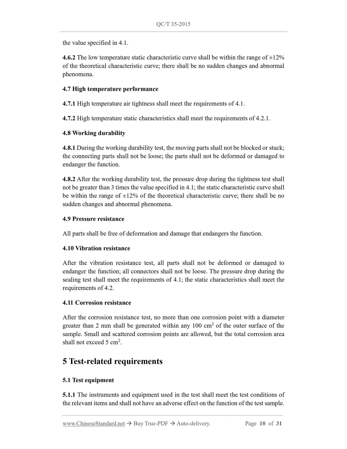
Place control valves A11 and A12 in the inflation position. Inflate from sample air inlets
11 and 12 to. Then place c...
Share
