1
/
of
12
PayPal, credit cards. Download editable-PDF & invoice in 1 second!
QC/T 626-2019 English PDF (QCT626-2019)
QC/T 626-2019 English PDF (QCT626-2019)
Regular price
$325.00 USD
Regular price
Sale price
$325.00 USD
Unit price
/
per
Shipping calculated at checkout.
Couldn't load pickup availability
Delivery: 3 seconds. Download true-PDF + Invoice.
Get QUOTATION in 1-minute: Click QC/T 626-2019
Historical versions: QC/T 626-2019
Preview True-PDF (Reload/Scroll if blank)
QC/T 626-2019: Motor vehicles - Window regulator
QC/T 626-2019
QC
AUTOMOBILE INDUSTRY STANDARD
OF THE PEOPLE’S REPUBLIC OF CHINA
ICS 43.040.60
T 26
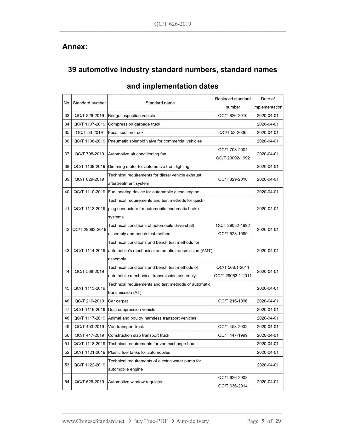
Replacing QC/T 626-2008, QC/T 636-2014
Motor vehicles - Window regulator
ISSUED ON: NOVEMBER 11, 2019
IMPLEMENTED ON: APRIL 01, 2020
Issued by: Ministry of Industry and Information Technology of PRC
Table of Contents
Foreword ... 7
1 Scope ... 9
2 Normative references ... 9
3 Terms and definitions ... 9
4 Requirements ... 10
5 Test method ... 15
6 Inspection rules ... 27
7 Marking, packaging, transportation, storage ... 29
Motor vehicles - Window regulator
1 Scope
This standard specifies the terms and definitions, requirements, test methods, inspection
rules, signs, packaging, transportation, storage of window regulator for motor vehicles.
This standard applies to the manual window regulator AND electric window regulator,
which has a nominal voltage of 12 V and 24 V, as used on motor vehicles. Its structure
form relates to a rope type window regulator and a gear arm window regulator. The
window regulator, in other structural forms, may refer to this standard for
implementation.
2 Normative references
The following documents are essential to the application of this document. For the dated
documents, only the versions with the dates indicated are applicable to this document;
for the undated documents, only the latest version (including all the amendments) is
applicable to this standard.
GB/T 4942.1-2006 Degrees of protection provided by the integral design of rotating
electrical machined (IP code) - Classification
GB/T 10125 Corrosion tests in artificial atmospheres - Salt spray tests (ISO
9227:2006, IDT)
GB/T 30512 Requirements for prohibited substances on automobiles
GB 34660 Road vehicles - Requirements and test methods of electromagnetic
compatibility
ISO 12103-1 Road vehicles - Test contaminants for filter evaluation - Part 1: Arizona
test dust
3 Terms and definitions
The following terms and definitions apply to this document.
3.1
Window regulator
The device, which can make the vehicle's window glass rise or fall along the window
glass channel, OR stop at any position (hereinafter referred to as regulator).
3.2
Window glass channel
A component, which guide the glass, when the vehicle's window glass is moved up
and down (hereinafter referred to as the guide channel).
3.3
Travel speed
The ratio -- of the travel of the vehicle window glass from the upper stop point
(lower stop point) to the lower stop point (upper stop point) TO the time to cover
such travel.
3.4
Slid-up excess force
When the vehicle's window glass rises, the force, which is obtained, by subtracting
the resistance (glass gravity, sliding resistance, etc.) from the raising force.
4 Requirements
4.1 The regulator shall comply with the requirements of this standard. It shall be
manufactured, in accordance with the product patterns and design documents, as
approved by the provisions.
4.2 The coating and plating and the chemical treatment layer of the metal parts of the
regulator shall be uniform AND have no obvious defect.
4.3 The surface of the plastic parts of the regulator shall be flat, no cracks, injection
molding defects, or deformation which affects use.
4.4 In the regulator, the content of prohibition material, such as lead, mercury, cadmium,
polybrominated biphenyls (PBBs), polybrominated diphenyl ether (PBDES), shall
comply with the provisions of GB/T 30512.
4.5 The electric regulator, which has a nominal voltage of 12 V, shall operate smoothly,
within the operating voltage range of 9 ~ 16 V. The electric regulator, which has a
nominal voltage of 24 V, shall operate smoothly, within the operating voltage range of
18 ~ 32 V.
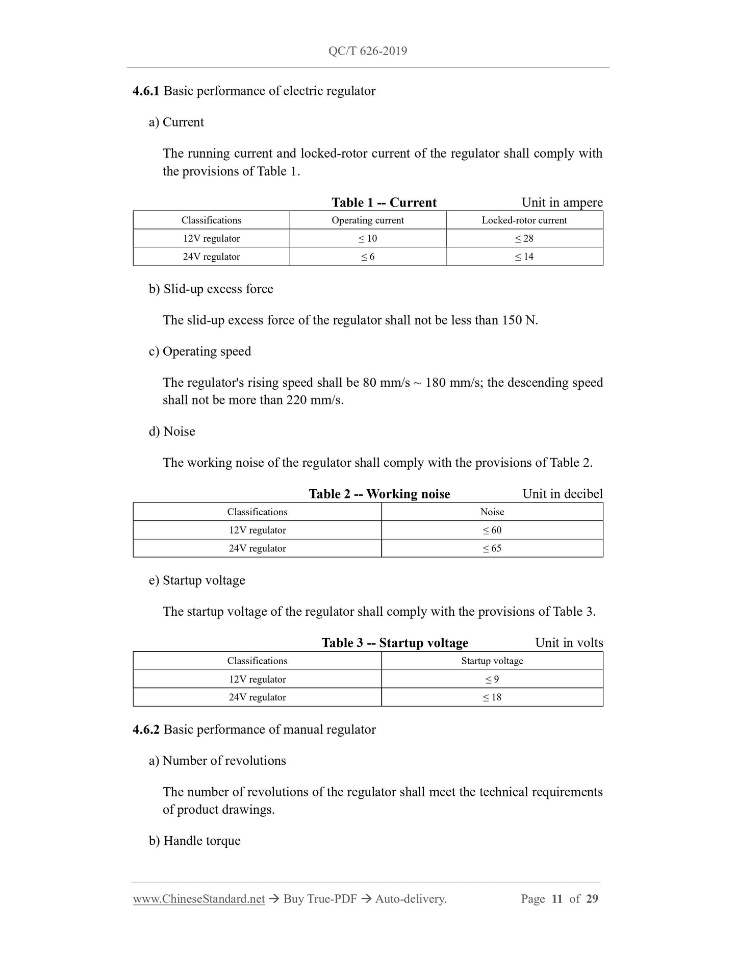
4.6 Basic performance
The maximum static handle torque of the regulator shall be no more than 1.8 N·m.
c) Glass decreasing
When the regulator rises to any position, after the handle torque is removed, the
decrease, in the midpoint of the window glass bottom, is not more than 3 mm.
d) Movement parallelism
The movement parallelism of the regulator, to any position, shall not be more than
0.3 mm/100 mm (for the gear single arm type and the rope type, it shall not be
more than 0.5 mm/100 mm).
4.7 Self-locking
The regulator shall be able to self-lock, in any position, in the window glass stroke.
When a 600 N load is applied on the regulator's glass bracket, the decrease of glass
bracket shall be not more than 5 mm, AND the regulator shall not be damaged.
4.8 Rotational gap of glass bracket
After the test in 5.8, the rotational gap of glass bracket shall not be more than 20 mm.
4.9 Vibration resistance
After the test in 5.9, each component shall not have unfavorable phenomenon which
may affects use, such as cracking, looseness, deformation, etc. The performance shall
comply with the provisions of 4.6.
4.10 Corrosion resistance
After the test in 5.10, it allows its performance in 4.6 to deviate for ± 20%; the main
surface of the metal parts has no substrate corrosion.
4.11 Durability
The regulator shall be able to withstand durability test. After the test, the function is
functioning; the operation is stable; there is no abnormal phenomenon, such as
abnormal sound, tooth slippage, slipping, jamming. The components of the regulator
shall have no crack or deformation, which may affect the use.
4.11.1 Durability of electric regulator
After the test in 5.11.1, it allows its performance in 4.6.1 and 4.7 to deviate by ± 20%,
as compared with that before the test.
Number of cycles:
a) Front door: 10000 cycles;
b) Back door: 7000 cycles.
4.11.2 Durability of manual regulator
After the test in 5.11.2, it allows its performance in 4.6.2 and 4.7 to deviate by ± 20%,
as compared with that before the test.
Number of cycles:
a) Front door: 5000 cycles;
b) Back door: 3000 cycles.
4.12 Overload strength
4.12.1 Overload strength of electric regulator
After the test in 5.12.1, its performance shall comply with the provisions of 4.6.1.
4.12.2 Overload strength of manual regulator
After the test in 5.12.2, the part shall have no cracks and permanent deformation; the
transmission mechanism shall have no gear out; its performance shall comply with the
provisions of 4.6.2.
4.13 Electric regulator other requirements
4.13.1 High-temperature resistance
After the test in 5.13.1, the elevator performance shall comply with the provisions of
Table 4.
4.13.2 Low-temperature resistance
After the test in 5.13.2, the performance of the regulator shall comply with the
provisions of Table 5.
e) Measurement of startup voltage: Install the regulator on the simulated tooling, to
block the glass bracket at the upper stop point, under the test voltage. Adjust the
supply voltage, under the unload conditions, run the regulator to drop the glass
bracket. Record the startup voltage value, when the bracket is falling.
5.6.2 Test of basic performance of manual regulator
a) Measurement of number of revolutions: Install the regulator on the simulated
tooling. Record the number of revolutions of the shaft of the window glass bracket,
when it moves from the lower stop point to the upper stop point.
b) Measurement of handle torque: Install the regulator on the simulated tooling.
Under the load conditions, rotate the handle in the clockwise or counterclockwise
direction, so that the regulator can move freely. In the travel of the reg...
Get QUOTATION in 1-minute: Click QC/T 626-2019
Historical versions: QC/T 626-2019
Preview True-PDF (Reload/Scroll if blank)
QC/T 626-2019: Motor vehicles - Window regulator
QC/T 626-2019
QC
AUTOMOBILE INDUSTRY STANDARD
OF THE PEOPLE’S REPUBLIC OF CHINA
ICS 43.040.60
T 26
Replacing QC/T 626-2008, QC/T 636-2014
Motor vehicles - Window regulator
ISSUED ON: NOVEMBER 11, 2019
IMPLEMENTED ON: APRIL 01, 2020
Issued by: Ministry of Industry and Information Technology of PRC
Table of Contents
Foreword ... 7
1 Scope ... 9
2 Normative references ... 9
3 Terms and definitions ... 9
4 Requirements ... 10
5 Test method ... 15
6 Inspection rules ... 27
7 Marking, packaging, transportation, storage ... 29
Motor vehicles - Window regulator
1 Scope
This standard specifies the terms and definitions, requirements, test methods, inspection
rules, signs, packaging, transportation, storage of window regulator for motor vehicles.
This standard applies to the manual window regulator AND electric window regulator,
which has a nominal voltage of 12 V and 24 V, as used on motor vehicles. Its structure
form relates to a rope type window regulator and a gear arm window regulator. The
window regulator, in other structural forms, may refer to this standard for
implementation.
2 Normative references
The following documents are essential to the application of this document. For the dated
documents, only the versions with the dates indicated are applicable to this document;
for the undated documents, only the latest version (including all the amendments) is
applicable to this standard.
GB/T 4942.1-2006 Degrees of protection provided by the integral design of rotating
electrical machined (IP code) - Classification
GB/T 10125 Corrosion tests in artificial atmospheres - Salt spray tests (ISO
9227:2006, IDT)
GB/T 30512 Requirements for prohibited substances on automobiles
GB 34660 Road vehicles - Requirements and test methods of electromagnetic
compatibility
ISO 12103-1 Road vehicles - Test contaminants for filter evaluation - Part 1: Arizona
test dust
3 Terms and definitions
The following terms and definitions apply to this document.
3.1
Window regulator
The device, which can make the vehicle's window glass rise or fall along the window
glass channel, OR stop at any position (hereinafter referred to as regulator).
3.2
Window glass channel
A component, which guide the glass, when the vehicle's window glass is moved up
and down (hereinafter referred to as the guide channel).
3.3
Travel speed
The ratio -- of the travel of the vehicle window glass from the upper stop point
(lower stop point) to the lower stop point (upper stop point) TO the time to cover
such travel.
3.4
Slid-up excess force
When the vehicle's window glass rises, the force, which is obtained, by subtracting
the resistance (glass gravity, sliding resistance, etc.) from the raising force.
4 Requirements
4.1 The regulator shall comply with the requirements of this standard. It shall be
manufactured, in accordance with the product patterns and design documents, as
approved by the provisions.
4.2 The coating and plating and the chemical treatment layer of the metal parts of the
regulator shall be uniform AND have no obvious defect.
4.3 The surface of the plastic parts of the regulator shall be flat, no cracks, injection
molding defects, or deformation which affects use.
4.4 In the regulator, the content of prohibition material, such as lead, mercury, cadmium,
polybrominated biphenyls (PBBs), polybrominated diphenyl ether (PBDES), shall
comply with the provisions of GB/T 30512.
4.5 The electric regulator, which has a nominal voltage of 12 V, shall operate smoothly,
within the operating voltage range of 9 ~ 16 V. The electric regulator, which has a
nominal voltage of 24 V, shall operate smoothly, within the operating voltage range of
18 ~ 32 V.
4.6 Basic performance
The maximum static handle torque of the regulator shall be no more than 1.8 N·m.
c) Glass decreasing
When the regulator rises to any position, after the handle torque is removed, the
decrease, in the midpoint of the window glass bottom, is not more than 3 mm.
d) Movement parallelism
The movement parallelism of the regulator, to any position, shall not be more than
0.3 mm/100 mm (for the gear single arm type and the rope type, it shall not be
more than 0.5 mm/100 mm).
4.7 Self-locking
The regulator shall be able to self-lock, in any position, in the window glass stroke.
When a 600 N load is applied on the regulator's glass bracket, the decrease of glass
bracket shall be not more than 5 mm, AND the regulator shall not be damaged.
4.8 Rotational gap of glass bracket
After the test in 5.8, the rotational gap of glass bracket shall not be more than 20 mm.
4.9 Vibration resistance
After the test in 5.9, each component shall not have unfavorable phenomenon which
may affects use, such as cracking, looseness, deformation, etc. The performance shall
comply with the provisions of 4.6.
4.10 Corrosion resistance
After the test in 5.10, it allows its performance in 4.6 to deviate for ± 20%; the main
surface of the metal parts has no substrate corrosion.
4.11 Durability
The regulator shall be able to withstand durability test. After the test, the function is
functioning; the operation is stable; there is no abnormal phenomenon, such as
abnormal sound, tooth slippage, slipping, jamming. The components of the regulator
shall have no crack or deformation, which may affect the use.
4.11.1 Durability of electric regulator
After the test in 5.11.1, it allows its performance in 4.6.1 and 4.7 to deviate by ± 20%,
as compared with that before the test.
Number of cycles:
a) Front door: 10000 cycles;
b) Back door: 7000 cycles.
4.11.2 Durability of manual regulator
After the test in 5.11.2, it allows its performance in 4.6.2 and 4.7 to deviate by ± 20%,
as compared with that before the test.
Number of cycles:
a) Front door: 5000 cycles;
b) Back door: 3000 cycles.
4.12 Overload strength
4.12.1 Overload strength of electric regulator
After the test in 5.12.1, its performance shall comply with the provisions of 4.6.1.
4.12.2 Overload strength of manual regulator
After the test in 5.12.2, the part shall have no cracks and permanent deformation; the
transmission mechanism shall have no gear out; its performance shall comply with the
provisions of 4.6.2.
4.13 Electric regulator other requirements
4.13.1 High-temperature resistance
After the test in 5.13.1, the elevator performance shall comply with the provisions of
Table 4.
4.13.2 Low-temperature resistance
After the test in 5.13.2, the performance of the regulator shall comply with the
provisions of Table 5.
e) Measurement of startup voltage: Install the regulator on the simulated tooling, to
block the glass bracket at the upper stop point, under the test voltage. Adjust the
supply voltage, under the unload conditions, run the regulator to drop the glass
bracket. Record the startup voltage value, when the bracket is falling.
5.6.2 Test of basic performance of manual regulator
a) Measurement of number of revolutions: Install the regulator on the simulated
tooling. Record the number of revolutions of the shaft of the window glass bracket,
when it moves from the lower stop point to the upper stop point.
b) Measurement of handle torque: Install the regulator on the simulated tooling.
Under the load conditions, rotate the handle in the clockwise or counterclockwise
direction, so that the regulator can move freely. In the travel of the reg...
Share