1
/
of
12
PayPal, credit cards. Download editable-PDF & invoice in 1 second!
YY 0592-2016 English PDF
YY 0592-2016 English PDF
Regular price
$165.00 USD
Regular price
Sale price
$165.00 USD
Unit price
/
per
Shipping calculated at checkout.
Couldn't load pickup availability
Delivery: 3 seconds. Download true-PDF + Invoice.
Get Quotation: Click YY 0592-2016 (Self-service in 1-minute)
Historical versions (Master-website): YY 0592-2016
Preview True-PDF (Reload/Scroll-down if blank)
YY 0592-2016: High intensity focused ultrasound therapy system
YY 0592-2016
High intensity focused ultrasound therapy system
ICS 11.040.50
C41
People's Republic of China pharmaceutical industry standards
Replacing YY 0592-2005
High-intensity focused ultrasound (HIFU) treatment system
2016-01-26 release
2018-01-01 implementation
State Food and Drug Administration released
Directory
Preface Ⅰ
1 range 1
2 Normative references 1
3 Terms and definitions 1
4 Categories 2
5 Requirements 3
6 test method 5
7 inspection rules 8
8 logo, packaging, transportation, storage 9
Foreword
This standard was drafted in accordance with the rules given in GB/T 1.1-2009.
Compared with YY 0592-2005, this standard in addition to editorial changes outside the main technical changes are as follows.
This standard replaces YY 0592-2005 "high intensity focused ultrasound (HIFU) treatment system."
--- Removed some of the terms and definitions repeated with other reference standards (2005 edition 3.2,3.3,3.4,3.5,3.6,3.7);
--- Increased vertical positioning accuracy requirements (see 5.5.2);
--- Increasing the relevant requirements of electromagnetic compatibility (see 5.11);
--- Removed the.2005 edition of Appendix A.
This standard proposed by the State Food and Drug Administration.
This standard by the National Medical Standardization Technical Committee Medical Ultrasound Equipment Standardization Technical Committee (SAC/TC10/SC2)
Focused.
This standard was drafted. Hubei State Administration of Food and Drug Quality Supervision, Inspection and Testing Center, Chongqing Haifu Medical Technology Unit
Co., Ltd., Wuxi Haiying Electronic Medical System Co., Ltd.
The main drafters of this standard. Jiang Shilin, Ye Fangwei, Wang Guoying, Li Tao.
This standard was first released in December.2005.
High-intensity focused ultrasound (HIFU) treatment system
1 Scope
This standard specifies the terms and definitions High-intensity focused ultrasound (HIFU) treatment system, classification, requirements, test methods, test rules to
And logo, packaging, transportation and storage.
This standard applies to in vitro focused high intensity focused ultrasound (HIFU) treatment system (hereinafter referred to as HIFU treatment system). System use
In vitro high intensity focused ultrasound ablation.
2 Normative references
The following documents for the application of this document is essential. For dated references, only the dated version applies to this article
Pieces. For undated references, the latest edition (including all amendments) applies to this document.
GB/T 191 Packaging - Pictorial signs
GB/T 3947-1996 Acoustics terminology
Medical electrical equipment - Part 1. General requirements for safety
GB/T 14710 medical appliances environmental requirements and test methods
GB/T 19890-2005 Acoustic high-intensity focused ultrasound (HIFU) measurement of sound power and sound field characteristics
YY/T 0162.1-2009 Medical ultrasound equipment grade series - Part 1. B ultrasound diagnostic equipment
YY 0505 Medical electrical equipment Part 1-2. General requirements for safety Collateral standards. EMC requirements and tests
3 Terms and definitions
GB/T 3947-1996 and GB/T 19890-2005 and the following terms and definitions apply to this document.
3.1
The focused ultrasound source, which is made up of unit transducers or multiple transducer arrays, emits ultrasound through the sound-transmitting medium to the normal human group
Weave Acceptable sound intensity through the body surface, the energy accumulation in the target tissue, causing its coagulation necrosis (or inactivated) treatment system.
3.2
Acoustical pressure field Acousticpressurefocalregion
Focal domain
The volume of space enclosed by the focal point that contains the sound pressure and whose sound pressure level is 6dB below the peak sound pressure (0dB).
3.3
Acoustic pressure focal area Acousticpressurefocalarea
The area enclosed by the sound pressure focal plane, which surrounds the focal point of sound pressure and whose sound pressure level is 6 dB below the peak sound pressure (0 dB).
Unit. square millimeter, mm2.
3.4
Focal domain horizontal size transversesizeoffocalregion
On a sound pressure focal plane, the distance between two points where the straight line passing through the peak of the sound pressure crosses the focal field interface.
Unit. mm, mm.
Note. In GB/T 19890-2005, the horizontal and vertical focal lengths are referred to as "-6 dB focal length (FWHM)".
3.5
Focal length vertical size longitudinalsizeoffocalregion
Distance between two points where the beam axis intersects the focal field interface.
Unit. mm, mm.
3.6
Mainlobe majorlobe (mainlobe)
The pressure profile on the sound pressure focal plane contains the lobe of the maximum square integral of the pulse sound pressure.
3.7
Sidelobe sidelobe
Acoustic pressure in the plane of the sound pressure distribution, in addition to the main lobe all the other lobes.
3.8
Axial submaximal pressure secondarymaximumacousticpressureonbeamaxis
The maximum sound pressure outside the acoustic pressure range of the sound beam axis.
Unit. Pa, Pa.
3.9
Location device localizationdevice
Medical imaging equipment and related devices for determining the spatial location of target tissue and monitoring during treatment.
3.10
Target location targetlocation
The manufacturer prescribes a target tissue location to the operator with some sort of positioning indicia.
3.11
Positioning device positioningdevice
By adjusting the position of the patient or the location of the ultrasound source (or ultrasound beam), the target tissue coincides with the target location.
3.12
Treatment head treatmenthead
Components made up of transducers and related parts that apply ultrasound to the patient's body.
4 categories
4.1 Product Classification
4.1.1 Press the ultrasonic output waveform, divided into continuous wave, pulse modulation and pulse wave.
4.1.2 Focusing transducer structure, divided into cell focus and multi-focus.
4.2 product composition
HIFU treatment system generally consists of the following devices (or parts).
a) Treatment of head and acoustic coupling device;
b) ultrasonic power generator;
c) positioning device;
d) Positioning device;
e) control device;
f) Patient carrying device;
g) water treatment and water temperature control device;
h) Software.
5 requirements
5.1 sound field characteristics
5.1.1 Sound pressure focusing area (horizontal focal region size)
Should not be more than the nominal value announced by the manufacturer. Sound pressure focusing area is given as follows.
Select the direction containing the maximum focal length of the horizontal direction of the X-axis, perpendicular to the direction of the Y-axis; with these two axial Faraway transverse ruler
Inch multiplication formula to represent.
5.1.2 Focal length of the vertical area
Should not be more than the nominal value announced by the manufacturer.
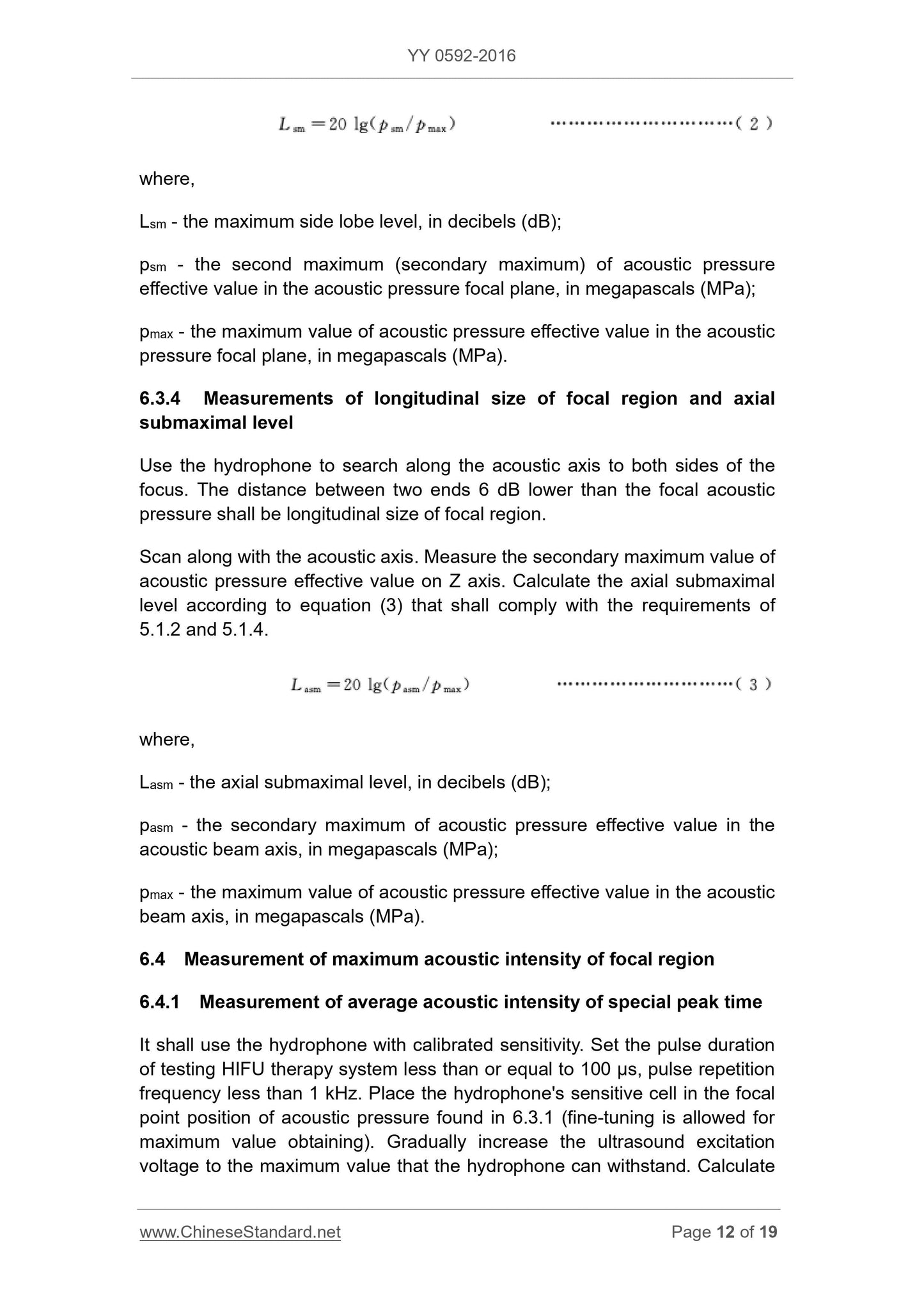
5.1.3 Maximum side-lobe level
The side lobe amplitude at the sound pressure focal plane should be 8 dB above the main lobe amplitude (focal sound pressure).
5.1.4 Axial submaximal level
Axial submaximal pressure should be lower than the focal sound pressure 8dB above.
5.1.5 Focal area maximum sound intensity
The spatial peak time average sound intensity (Ispta) should not be less than 1000W/cm2. Manufacturers should publish the maximum output sound power under the conditions of coke
Field maximum intensity and deviation.
Note. In the test conditions are not allowed (especially continuous wave ultrasonic output device), -6dB sound beam area can be used within the time-average spatial intensity of the spatial average
(ISAL) instead of space peak time average sound intensity.
5.2 sound frequency deviation
The manufacturer shall publish the nominal operating frequency of the transducer sound. The maximum deviation of sound operating frequency should not exceed ± 15% of the nominal value.
5.3 Ultrasound power and control
5.3.1 The manufacturer shall publish the maximum output sound power and deviation.
5.3.2 The HIFU treatment system must have ultrasonic output energy control to reduce the sound intensity or sound power in the focal region to the maximum
Less than 20%.
5.4 positioning device
5.4.1 If using ultrasound imaging equipment as a positioning device, the main technical performance requirements are as follows.
a) Image resolution, geometric position accuracy, blind area should reach YY/T 0162.1-2009 B file or A file corresponding provisions;
b) The detection depth should not be less than the distance from the probe end to the far end of the focal length.
5.4.2 If the use of other medical imaging equipment as a positioning device, its technical performance should meet the HIFU treatment system positioning requirements.
5.4.3 monitoring function. During the treatment, the positioning device should be able to real-time or near real-time manner on the target tissue size, shape, patient position into
Line monitoring.
Note. The standard "quasi real-time" refers to the treatment of ultrasound in order to avoid the impact on the monitoring images, the use of ultrasound imaging of the gap for imaging
Discontinuous instant images.
5.5 Positioning device
5.5.1 range of motion and error
Positioning device (head or patient support device) the maximum axial travel, the cumulative error and the treatment of head, ultrasound imaging equipment
Moving angle should be consistent with the manufacturer's rules.
5.5.2 Positioning accuracy
The deviation of the target mark from the actual focus should be no more than 3 mm in the XY plane and no more than 5 mm in the Z (longitudinal) axis.
5.6 treatment effect evaluation function
HIFU treatment system should be given for the evaluation of the treatment effect (that is, tissue coagulation necrosis) reference information, manufacturers should be given every
Reference information for assessing the effect of treatment before and after sonication.
5.7 Information to be published by the manufacturer
For each treatment head/transducer, the manufacturer shall publish the following parameters in the accompanying document.
a) maximum output sound power;
b) sound working frequency;
c) sound focal length;
d) Focal area horizontal size, focal length vertical size;
e) the maximum sound intensity and deviation of the focal region under the maximum output sound power;
f) the maximum sidelobe level and its position relative to the focal field;
g) Axial sub-maximal level and its position relative to the focal field.
5.8 Appearance and structure
5.8.1 Appearance should be neat, uniform color, no scars, scratches and other defects.
5.8.2 Control and adjustment agencies should be flexible and reliable, no loose fastening parts.
5.8.3 rubber, plastic parts should be no blistering, cracking, deformation phenomenon.
5.8.4 Sinks, water bags and water connections should be no media leakage phenomenon.
5.9 water treatment device
The media water temperature control, degassing device HIFU treatment system, the effect of the treatment requirements are as follows.
a) The control range and error of water temperature should meet the requirements of the manufacturer;
b) Degassing water oxygen dissolved no more than 4mg/L.
5.10 Electrical Safety Requirements
Shall comply with GB 9706.1-2007 and other applicable parallel or special safety standards related requirements.
5.11 Electromagnetic compatibility
Should comply with the relevant requirements YY 0505.
5.12 environmental test requirements
HIFU treatment system environmental test conditions should be GB/T 14710 requirements, by the manufacturer in the enterprise product standards to determine the appropriate
Of the test group and test items. When the overall environmental test is not feasible, the climatic environmental test and the mechanical environmental test under the working conditions can
Not carried out, only the key components (such as ultrasonic power source, control part) for storage test, and then check the assembly after the work is normal.
6 test methods
6.1 Test environment
6.1.1 Ambient temperature 10 ℃ ~ 40 ℃, relative humidity 30% ~ 75%, atmospheric pressure range. 700hPa ~ 1060hPa, water-cooled set
Prepared water inlet temperature is not higher than 25 ℃.
6.1.2 Test should avoid external vibration, electromagnetic fields and other interference.
6.2 Measurement System Requirements
Shall comply with the provisions of Chapter 5 GB/T 19890-2005.
Note. The electrical power stability of the HIFU treatment system under test is changed from 10%/4h as specified in GB/T 19890-2005 to 15%/4h.
6.3 Measurement of sound field distribution characteristics
Sound field distribution characterization test Since only the relative sound pressure level is required, water with uncalibrated sensitivity but less than 10% nonlinear distortion can be used
Listener. Ultrasound output power should be set in the hydrophone without damage under the premise of the larger value to try to truly reflect the sound field distribution. Specific test
Test methods can refer to GB/T 19890-2005 Chapter 7.
6.3.1 Measurement of sound pressure focal point position
Repeatedly adjust the azimuth pitch angle of the 3D scanning mechanism and the hydrophone and adjust the two directional angles of the focusing transducer (if adjustable) to make the water
The acoustic axis of the listener is acoustically coaxial with the major acoustic axis of the focusing transducer or transducer array and also requires that the common acoustic axis and the hydrophone be moved
A coordinate axis (such as the Z axis) parallel. Move the hydrophone along the common acoustic axis to find the focal point of the sound pressure of the HIFU treatment system under test
Set, record the sound pressure pmax.
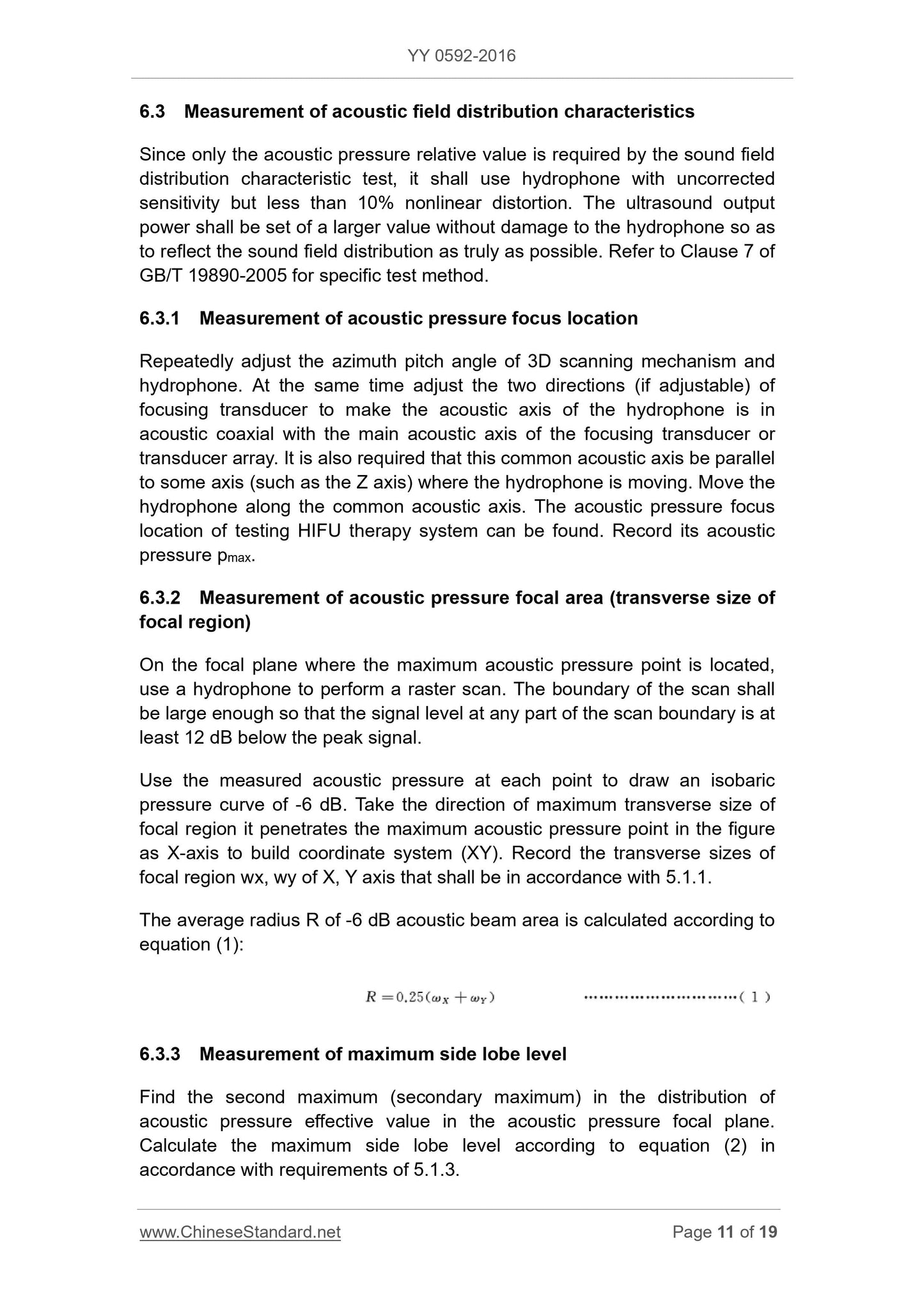
6.3.2 Measurement of sound pressure focal area (transverse dimension of the focal region)
In the focal plane where the maximum pressure point is located, a hydrophone is used to perform the grid scanning. The boundary of the scanning should be large enough to allow scanning beyond the boundary
What part of the signal level at least 12dB below t...
Get Quotation: Click YY 0592-2016 (Self-service in 1-minute)
Historical versions (Master-website): YY 0592-2016
Preview True-PDF (Reload/Scroll-down if blank)
YY 0592-2016: High intensity focused ultrasound therapy system
YY 0592-2016
High intensity focused ultrasound therapy system
ICS 11.040.50
C41
People's Republic of China pharmaceutical industry standards
Replacing YY 0592-2005
High-intensity focused ultrasound (HIFU) treatment system
2016-01-26 release
2018-01-01 implementation
State Food and Drug Administration released
Directory
Preface Ⅰ
1 range 1
2 Normative references 1
3 Terms and definitions 1
4 Categories 2
5 Requirements 3
6 test method 5
7 inspection rules 8
8 logo, packaging, transportation, storage 9
Foreword
This standard was drafted in accordance with the rules given in GB/T 1.1-2009.
Compared with YY 0592-2005, this standard in addition to editorial changes outside the main technical changes are as follows.
This standard replaces YY 0592-2005 "high intensity focused ultrasound (HIFU) treatment system."
--- Removed some of the terms and definitions repeated with other reference standards (2005 edition 3.2,3.3,3.4,3.5,3.6,3.7);
--- Increased vertical positioning accuracy requirements (see 5.5.2);
--- Increasing the relevant requirements of electromagnetic compatibility (see 5.11);
--- Removed the.2005 edition of Appendix A.
This standard proposed by the State Food and Drug Administration.
This standard by the National Medical Standardization Technical Committee Medical Ultrasound Equipment Standardization Technical Committee (SAC/TC10/SC2)
Focused.
This standard was drafted. Hubei State Administration of Food and Drug Quality Supervision, Inspection and Testing Center, Chongqing Haifu Medical Technology Unit
Co., Ltd., Wuxi Haiying Electronic Medical System Co., Ltd.
The main drafters of this standard. Jiang Shilin, Ye Fangwei, Wang Guoying, Li Tao.
This standard was first released in December.2005.
High-intensity focused ultrasound (HIFU) treatment system
1 Scope
This standard specifies the terms and definitions High-intensity focused ultrasound (HIFU) treatment system, classification, requirements, test methods, test rules to
And logo, packaging, transportation and storage.
This standard applies to in vitro focused high intensity focused ultrasound (HIFU) treatment system (hereinafter referred to as HIFU treatment system). System use
In vitro high intensity focused ultrasound ablation.
2 Normative references
The following documents for the application of this document is essential. For dated references, only the dated version applies to this article
Pieces. For undated references, the latest edition (including all amendments) applies to this document.
GB/T 191 Packaging - Pictorial signs
GB/T 3947-1996 Acoustics terminology
Medical electrical equipment - Part 1. General requirements for safety
GB/T 14710 medical appliances environmental requirements and test methods
GB/T 19890-2005 Acoustic high-intensity focused ultrasound (HIFU) measurement of sound power and sound field characteristics
YY/T 0162.1-2009 Medical ultrasound equipment grade series - Part 1. B ultrasound diagnostic equipment
YY 0505 Medical electrical equipment Part 1-2. General requirements for safety Collateral standards. EMC requirements and tests
3 Terms and definitions
GB/T 3947-1996 and GB/T 19890-2005 and the following terms and definitions apply to this document.
3.1
The focused ultrasound source, which is made up of unit transducers or multiple transducer arrays, emits ultrasound through the sound-transmitting medium to the normal human group
Weave Acceptable sound intensity through the body surface, the energy accumulation in the target tissue, causing its coagulation necrosis (or inactivated) treatment system.
3.2
Acoustical pressure field Acousticpressurefocalregion
Focal domain
The volume of space enclosed by the focal point that contains the sound pressure and whose sound pressure level is 6dB below the peak sound pressure (0dB).
3.3
Acoustic pressure focal area Acousticpressurefocalarea
The area enclosed by the sound pressure focal plane, which surrounds the focal point of sound pressure and whose sound pressure level is 6 dB below the peak sound pressure (0 dB).
Unit. square millimeter, mm2.
3.4
Focal domain horizontal size transversesizeoffocalregion
On a sound pressure focal plane, the distance between two points where the straight line passing through the peak of the sound pressure crosses the focal field interface.
Unit. mm, mm.
Note. In GB/T 19890-2005, the horizontal and vertical focal lengths are referred to as "-6 dB focal length (FWHM)".
3.5
Focal length vertical size longitudinalsizeoffocalregion
Distance between two points where the beam axis intersects the focal field interface.
Unit. mm, mm.
3.6
Mainlobe majorlobe (mainlobe)
The pressure profile on the sound pressure focal plane contains the lobe of the maximum square integral of the pulse sound pressure.
3.7
Sidelobe sidelobe
Acoustic pressure in the plane of the sound pressure distribution, in addition to the main lobe all the other lobes.
3.8
Axial submaximal pressure secondarymaximumacousticpressureonbeamaxis
The maximum sound pressure outside the acoustic pressure range of the sound beam axis.
Unit. Pa, Pa.
3.9
Location device localizationdevice
Medical imaging equipment and related devices for determining the spatial location of target tissue and monitoring during treatment.
3.10
Target location targetlocation
The manufacturer prescribes a target tissue location to the operator with some sort of positioning indicia.
3.11
Positioning device positioningdevice
By adjusting the position of the patient or the location of the ultrasound source (or ultrasound beam), the target tissue coincides with the target location.
3.12
Treatment head treatmenthead
Components made up of transducers and related parts that apply ultrasound to the patient's body.
4 categories
4.1 Product Classification
4.1.1 Press the ultrasonic output waveform, divided into continuous wave, pulse modulation and pulse wave.
4.1.2 Focusing transducer structure, divided into cell focus and multi-focus.
4.2 product composition
HIFU treatment system generally consists of the following devices (or parts).
a) Treatment of head and acoustic coupling device;
b) ultrasonic power generator;
c) positioning device;
d) Positioning device;
e) control device;
f) Patient carrying device;
g) water treatment and water temperature control device;
h) Software.
5 requirements
5.1 sound field characteristics
5.1.1 Sound pressure focusing area (horizontal focal region size)
Should not be more than the nominal value announced by the manufacturer. Sound pressure focusing area is given as follows.
Select the direction containing the maximum focal length of the horizontal direction of the X-axis, perpendicular to the direction of the Y-axis; with these two axial Faraway transverse ruler
Inch multiplication formula to represent.
5.1.2 Focal length of the vertical area
Should not be more than the nominal value announced by the manufacturer.
5.1.3 Maximum side-lobe level
The side lobe amplitude at the sound pressure focal plane should be 8 dB above the main lobe amplitude (focal sound pressure).
5.1.4 Axial submaximal level
Axial submaximal pressure should be lower than the focal sound pressure 8dB above.
5.1.5 Focal area maximum sound intensity
The spatial peak time average sound intensity (Ispta) should not be less than 1000W/cm2. Manufacturers should publish the maximum output sound power under the conditions of coke
Field maximum intensity and deviation.
Note. In the test conditions are not allowed (especially continuous wave ultrasonic output device), -6dB sound beam area can be used within the time-average spatial intensity of the spatial average
(ISAL) instead of space peak time average sound intensity.
5.2 sound frequency deviation
The manufacturer shall publish the nominal operating frequency of the transducer sound. The maximum deviation of sound operating frequency should not exceed ± 15% of the nominal value.
5.3 Ultrasound power and control
5.3.1 The manufacturer shall publish the maximum output sound power and deviation.
5.3.2 The HIFU treatment system must have ultrasonic output energy control to reduce the sound intensity or sound power in the focal region to the maximum
Less than 20%.
5.4 positioning device
5.4.1 If using ultrasound imaging equipment as a positioning device, the main technical performance requirements are as follows.
a) Image resolution, geometric position accuracy, blind area should reach YY/T 0162.1-2009 B file or A file corresponding provisions;
b) The detection depth should not be less than the distance from the probe end to the far end of the focal length.
5.4.2 If the use of other medical imaging equipment as a positioning device, its technical performance should meet the HIFU treatment system positioning requirements.
5.4.3 monitoring function. During the treatment, the positioning device should be able to real-time or near real-time manner on the target tissue size, shape, patient position into
Line monitoring.
Note. The standard "quasi real-time" refers to the treatment of ultrasound in order to avoid the impact on the monitoring images, the use of ultrasound imaging of the gap for imaging
Discontinuous instant images.
5.5 Positioning device
5.5.1 range of motion and error
Positioning device (head or patient support device) the maximum axial travel, the cumulative error and the treatment of head, ultrasound imaging equipment
Moving angle should be consistent with the manufacturer's rules.
5.5.2 Positioning accuracy
The deviation of the target mark from the actual focus should be no more than 3 mm in the XY plane and no more than 5 mm in the Z (longitudinal) axis.
5.6 treatment effect evaluation function
HIFU treatment system should be given for the evaluation of the treatment effect (that is, tissue coagulation necrosis) reference information, manufacturers should be given every
Reference information for assessing the effect of treatment before and after sonication.
5.7 Information to be published by the manufacturer
For each treatment head/transducer, the manufacturer shall publish the following parameters in the accompanying document.
a) maximum output sound power;
b) sound working frequency;
c) sound focal length;
d) Focal area horizontal size, focal length vertical size;
e) the maximum sound intensity and deviation of the focal region under the maximum output sound power;
f) the maximum sidelobe level and its position relative to the focal field;
g) Axial sub-maximal level and its position relative to the focal field.
5.8 Appearance and structure
5.8.1 Appearance should be neat, uniform color, no scars, scratches and other defects.
5.8.2 Control and adjustment agencies should be flexible and reliable, no loose fastening parts.
5.8.3 rubber, plastic parts should be no blistering, cracking, deformation phenomenon.
5.8.4 Sinks, water bags and water connections should be no media leakage phenomenon.
5.9 water treatment device
The media water temperature control, degassing device HIFU treatment system, the effect of the treatment requirements are as follows.
a) The control range and error of water temperature should meet the requirements of the manufacturer;
b) Degassing water oxygen dissolved no more than 4mg/L.
5.10 Electrical Safety Requirements
Shall comply with GB 9706.1-2007 and other applicable parallel or special safety standards related requirements.
5.11 Electromagnetic compatibility
Should comply with the relevant requirements YY 0505.
5.12 environmental test requirements
HIFU treatment system environmental test conditions should be GB/T 14710 requirements, by the manufacturer in the enterprise product standards to determine the appropriate
Of the test group and test items. When the overall environmental test is not feasible, the climatic environmental test and the mechanical environmental test under the working conditions can
Not carried out, only the key components (such as ultrasonic power source, control part) for storage test, and then check the assembly after the work is normal.
6 test methods
6.1 Test environment
6.1.1 Ambient temperature 10 ℃ ~ 40 ℃, relative humidity 30% ~ 75%, atmospheric pressure range. 700hPa ~ 1060hPa, water-cooled set
Prepared water inlet temperature is not higher than 25 ℃.
6.1.2 Test should avoid external vibration, electromagnetic fields and other interference.
6.2 Measurement System Requirements
Shall comply with the provisions of Chapter 5 GB/T 19890-2005.
Note. The electrical power stability of the HIFU treatment system under test is changed from 10%/4h as specified in GB/T 19890-2005 to 15%/4h.
6.3 Measurement of sound field distribution characteristics
Sound field distribution characterization test Since only the relative sound pressure level is required, water with uncalibrated sensitivity but less than 10% nonlinear distortion can be used
Listener. Ultrasound output power should be set in the hydrophone without damage under the premise of the larger value to try to truly reflect the sound field distribution. Specific test
Test methods can refer to GB/T 19890-2005 Chapter 7.
6.3.1 Measurement of sound pressure focal point position
Repeatedly adjust the azimuth pitch angle of the 3D scanning mechanism and the hydrophone and adjust the two directional angles of the focusing transducer (if adjustable) to make the water
The acoustic axis of the listener is acoustically coaxial with the major acoustic axis of the focusing transducer or transducer array and also requires that the common acoustic axis and the hydrophone be moved
A coordinate axis (such as the Z axis) parallel. Move the hydrophone along the common acoustic axis to find the focal point of the sound pressure of the HIFU treatment system under test
Set, record the sound pressure pmax.
6.3.2 Measurement of sound pressure focal area (transverse dimension of the focal region)
In the focal plane where the maximum pressure point is located, a hydrophone is used to perform the grid scanning. The boundary of the scanning should be large enough to allow scanning beyond the boundary
What part of the signal level at least 12dB below t...
Share