1
/
of
12
PayPal, credit cards. Download editable-PDF & invoice in 1 second!
YY 0775-2010 English PDF
YY 0775-2010 English PDF
Regular price
$150.00 USD
Regular price
Sale price
$150.00 USD
Unit price
/
per
Shipping calculated at checkout.
Couldn't load pickup availability
Delivery: 3 seconds. Download true-PDF + Invoice.
Get Quotation: Click YY 0775-2010 (Self-service in 1-minute)
Historical versions (Master-website): YY 0775-2010
Preview True-PDF (Reload/Scroll-down if blank)
YY 0775-2010: Teleradiotherapy treatment planning system accuracy of dosimetric calculation and test methods for high energy X(γ) beam
YY 0775-2010
Teleradiotherapy treatment planning system accuracy of dosimetric calculation and test methods for high energy X (γ) beam
ICS 11.040.60
C43
People's Republic of China pharmaceutical industry standards
Distance radiation treatment planning system
High Energy X (γ) beam dose calculation accuracy
Requirements and test methods
ofdosimetriccalculationandtestmethodsforhighenergyX (γ) beam
Issued on. 2010-12-27
2012-06-01 implementation
State Food and Drug Administration issued
Table of Contents
Introduction Ⅲ
1 Scope 1
2 Normative references 1
3 Terms and definitions
4 Requirements 1
4.1 Simple geometry 1
4.2 complex geometry 2
4.3 condition combination of complex geometry 2
4.4 outer edge of the radiation field 2
4.5 radiation field edge, the complex geometry and the central axis is blocked 2
5 Test Method 2
5.1 General test conditions 2
5.2 Test Example 4
5.3 simple geometry 4
4 5.4 complex geometry
5.5 condition combination of complex geometry 4
5.6 outer edge of the radiation field 4
5.7 radiation field edge, the complex geometry and the central axis is blocked 5
Appendix A (normative) Test Data 6
Appendix B (normative) Test Example 7
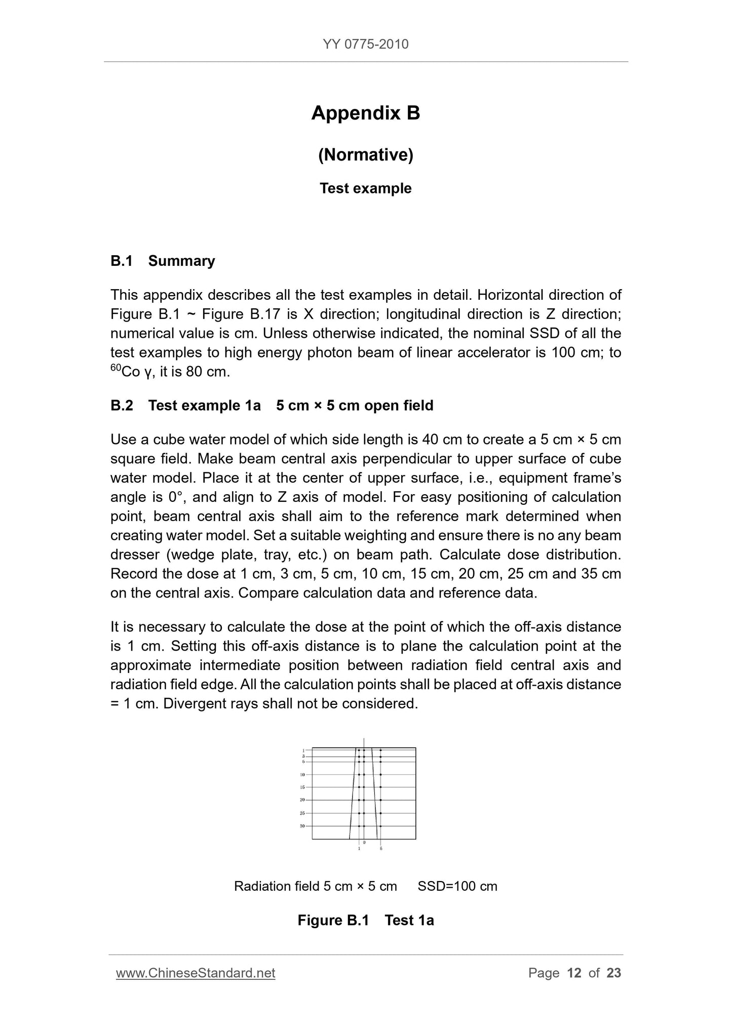
Figure B.1 Test 1a 7
Figure B.2 Test 1b 8
Figure B.3 Test 1c 8
Figure B.4 Test 2a 9
Figure B.5 Test 2b 9
Figure B.6 Test 310
Figure B.7 Test 410
Figure B.8 Test 511
Figure B.9 Test 611
Figure B.10 Test 712
Figure B.11 Test 8a 13
Figure B.12 Test 8b 13
Figure B.13 Test 8c 14
Figure B.14 Test 914
Figure B.15 Test 10a 15
Figure B.16 Test 10b 15
Figure B.17 test 11 and test 12 16
References 17
Foreword
All the technical contents of this standard is mandatory.
This standard was drafted in accordance with GB/T 1.1-2009 given rules.
Standard test data and test cases with Technical Report No. IAEA1540 test data (machine configuration data) and test
Test cases.
Please note that some of the content of this document may involve patents. Release mechanism of the present document does not assume responsibility for the identification of these patents.
The national standard therapy, nuclear medicine Standardization Technical Committee of Standardization Technical Committee appliances Medical radiation and radiation dosimetry equipment
(SAC/TC10/SC3) and focal points.
This standard was drafted. State Food and Drug Administration, Beijing Medical Device Quality Supervision, Inspection, Shenzhen Science and Technology Co., Haibo
the company.
The main drafters. Zhang Xin, Zhang Zhao Park, Xu Yan, Hu Jia, Qing Hou.
Distance radiation treatment planning system
High Energy X (γ) beam dose calculation accuracy
Requirements and test methods
1 Scope
This standard specifies the distance radiation treatment planning system (RadiotherapyTreatmentPlanningSystems, hereinafter referred to as
Accuracy requirements and test methods RTPS) dose calculation.
This standard applies to medical high-energy X-ray (4MV ~ 25MV), 60Coγ ray photon radiation having a long-distance radiotherapy dosimeter
Operator display RTPS function.
This standard does not apply to stereotactic radiotherapy and intensity modulated radiation therapy (IMRT) or other specialized radiotherapy techniques make
Radiation treatment planning systems, but application developers are encouraged to develop and use this as a validation standard dose calculation algorithm reference standard.
The standard test packets can not be used in clinical treatment planning.
2 Normative references
The following documents for the application of this document is essential. For dated references, only the dated version suitable for use herein
Member. For undated references, the latest edition (including any amendments) applies to this document.
GB/T 17857-1999 Medical imaging academic language (radiotherapy, nuclear medicine and radiation dosimetry equipment)
GB/T 18987-2003 Radiotherapy equipment Coordinates, movements and scales (IEC 61217.1996, IDT)
3 Terms and Definitions
GB/T 17857-1999 define the following terms and definitions apply to this document.
3.1
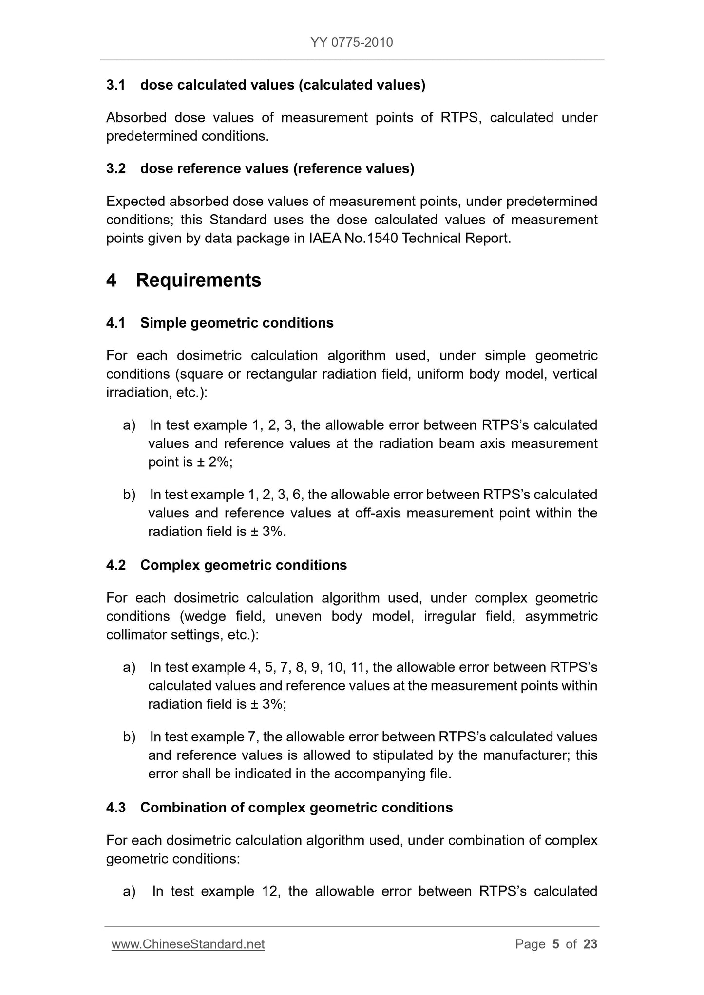
Dose calculated value (referred to as the calculated value) dosecalculatedvalues (calculatedvalues)
Absorbent magnitude RTPS calculated under predetermined conditions measuring point.
3.2
Dose reference value (referred to as the reference value) dosereferencevalues (referencevalues)
Measuring point under predetermined conditions absorbed dose expectation, this standard by measuring IAEA1540 Technical Report No. packets given
Point dose measurements.
4 Requirements
4.1 simple geometry
For each dose calculation algorithm used in (a square or rectangular portal, uniform phantom, vertical irradiation) simple geometry.
a) Test Example 1, 2, a beam of radiation tolerance of ± 2% RTPS dose calculated and reference values on-axis measurement point;
b) test cases allows RTPS dose calculated value and the reference value in the off-axis measurement point within the radiation field 1,2,3,6 error ± 3%.
4.2 complex geometry
For each dose calculation algorithms used in complex geometry (wedge field inhomogeneity phantom, wild irregular, asymmetric quasi
Collimator settings, etc.).
a) tolerance of RTPS dose calculated value and the reference value between the measurement points in the radiation field within the test cases 4,5,7,8,9,10,11
± 3%;
b) For the test of Example 7, allowing manufacturers otherwise specified tolerances RTPS dose calculated value and reference value, and should be random
This document explains the error.
4.3 condition combination of complex geometry
For each dose calculation algorithm, the complex geometry in combination.
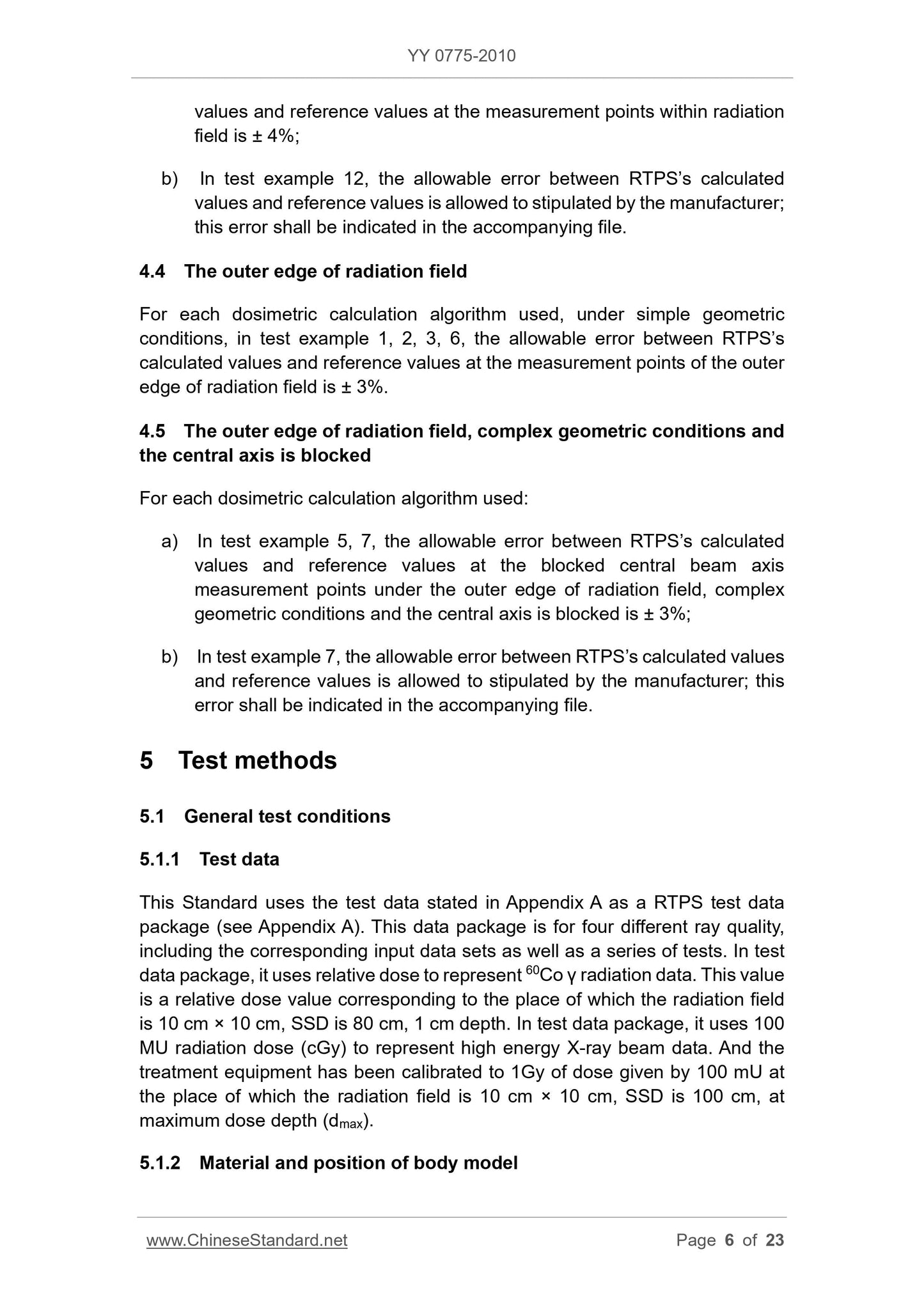
a) Test Example 12, the radiation field within the tolerance of the measuring point RTPS dose calculated value and a reference value of ± 4%;
b) For the 12 test cases, allowing manufacturers otherwise specified tolerances RTPS dose calculated value and reference value, and should follow
This document describes machine error.
4.4 portal outer edge
For each dose calculation algorithm used in the simple geometry, test cases 1,2,3,6 in the radiation field outside the measurement point on the edge
RTPS dose calculated values and the reference values of allowable error of ± 3%.
4.5 radiation field edge, the complex geometry and the central axis is blocked
For each dose calculation algorithm.
a) 5,7 test case in the radiation field outside the edge of the complex geometry and the central axis is blocked conditions, it obscured the central beam axis measurement point
Allow the RTPS dose calculated values and the reference values of error of ± 3%;
b) For the test of Example 7, allowing manufacturers otherwise specified tolerances RTPS dose calculated value and reference value, and should be random
This document explains the error.
5 Test methods
5.1 General test conditions
5.1.1 Test Data
Appendix A of this standard in the test data as a RTPS test packet (see Appendix A), the packet is not for the four
With ray quality, it contains the corresponding input data sets as well as a series of tests. Test packets of data relative 60Coγ radiation dose table
Shown, the value is relative to the radiation field is 10cm × 10cm, SSD is 80cm, the relative dose values 1cm depth (dref) at. Test Data
Package of high-energy X radiation beam data 100MU dose (cGy), said this time the treatment device has been calibrated to the size of the radiation field
10cm × 10cm, SSD is 100cm, the maximum dose depth (dmax) at a dose of irradiation 100MU given 1Gy.
Material and location 5.1.2 motif
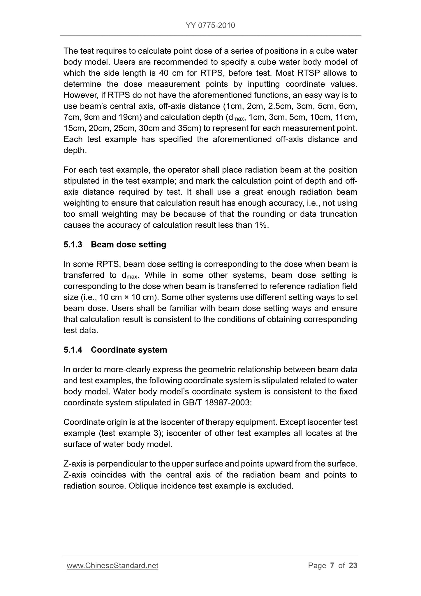
Test requirements to calculate a cube-point dose range of water mold body position. Recommends that users RTPS requirements before starting the test
A side length of 40cm cube water phantom. Most RTPS allows enter coordinates to determine dose calculation point. However, if the
RTPS does not have these features, a convenient practice is for each test point with the beam central axis, off-axis distance (1cm, 2cm,
2.5cm, 3cm, 5cm, 6cm, 7cm, 9cm and 19cm) and calculated depth (dmax, 1cm, 3cm, 5cm, 10cm, 11cm,
15cm, 20cm, 25cm, 30cm and 35cm) to represent. Each test case are provided for off-axis distance and depth of the need.
For each test case, the operator should be placed in the position of the radiation beam test cases specified, and identifies the required test depth and from wheelbase
From the calculation point. Use a large enough radiation beam weights to ensure there is enough calculation accuracy, ie without using weights is too small
Because it may result due to rounding or data truncation dose calculation accuracy of less than 1%.
5.1.3 beam dose setting
In some RPTS, the beam corresponding to the beam passing the dose setting dmax dose, while in other systems, the beam dose setting
Corresponding to the reference beam is transmitted to the radiation field size (ie 10cm × 10cm) at a dose dmax. There are other systems with various other ways provided
Fixed beam dose. Users should be familiar with the way the beam dose setting and to ensure that the results of and access to test data corresponding to the conditions of the same.
5.1.4 Coordinate System
In order to more clearly express beam geometry data and test cases, the following coordinate system is relative to the water phantom regulations. Water mold
Coordinate system consistent with GB/T 18987-2003 predetermined fixed coordinate system.
Coordinate origin at the center of treatment equipment and so on. In addition to other central test case (Test Example 3), all other test cases, and other centers are located in water
Phantom surface.
Z-axis perpendicular to the surface of the water surface by a phantom point on, the Z-axis and the radiation beam axle center consolidation point source of radiation, measured obliquely incident
Except test cases.
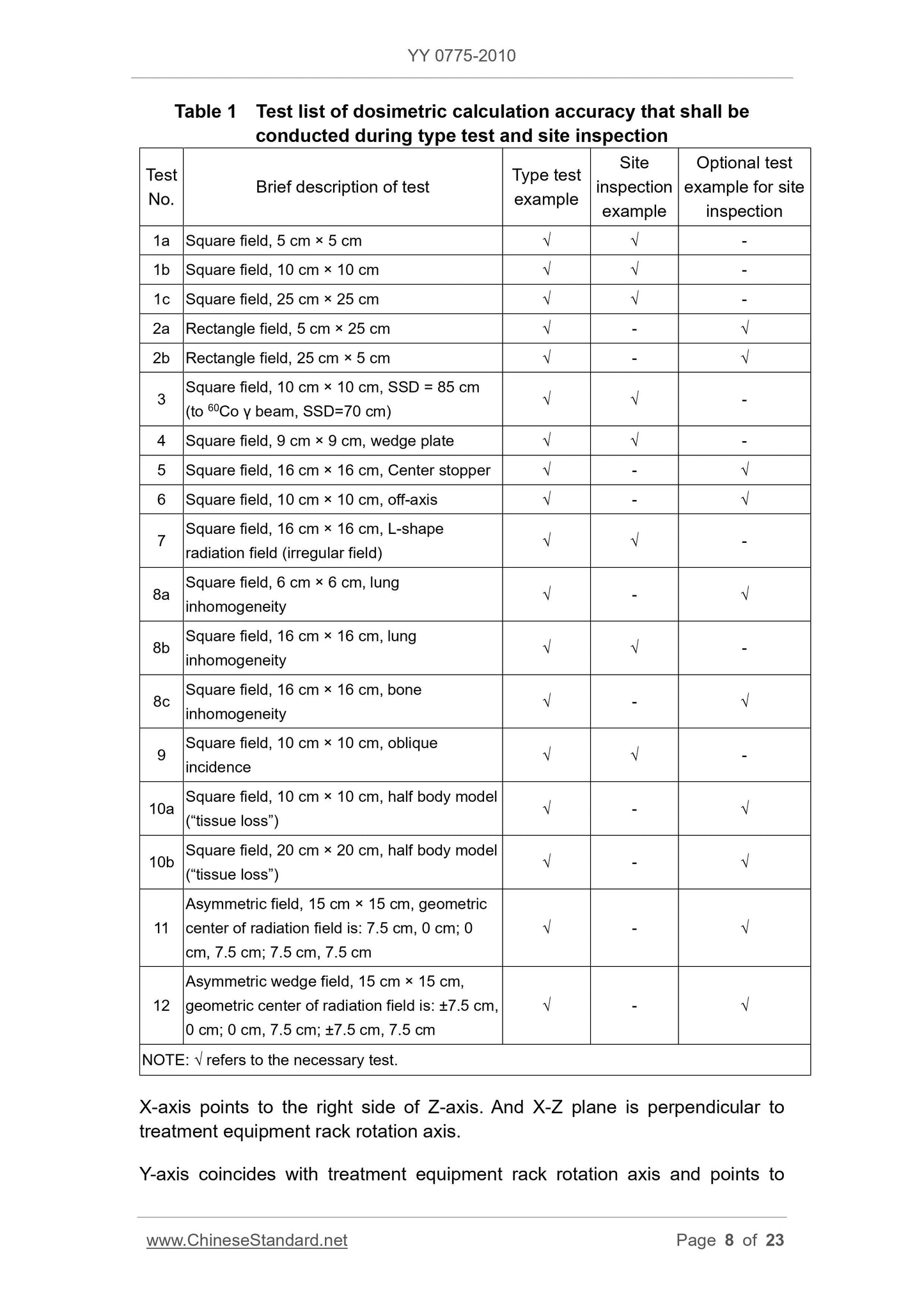
Type 1 dose calculation during the test and field test the accuracy of the test should be Table List
A brief description of test ID test
Type Test
Test Example
Site Inspection
Test Example
Site Inspection
Optional test case
1a wild side, 5cm × 5cm √ √ -
1b wild side, 10cm × 10cm √ √ -
1c wild side, 25cm × 25cm √ √ -
2a rectangular field, 5cm × 25cm √ - √
2b rectangle wild, 25cm × 5cm √ - √
Wild side, 10cm × 10cm, SSD = 85cm (for 60Coγ beam,
SSD = 70cm)
√ √ -
4 Wild side, 9cm × 9cm, wedge √ √ -
5 wild side, 16cm × 16cm, the center stopper √ - √
6 Wild side, 10cm × 10cm, off-axis √ - √
7 Wild side, 16cm × 16cm, L-shaped radiation field (irregular wild) √ √ -
8a wild side, 6cm × 6cm, lung inhomogeneity √ - √
8b wild side, 16cm × 16cm, lung inhomogeneity √ √ -
8c wild side, 16cm × 16cm, bone unevenness √ - √
9 Wild side, 10cm × 10cm, oblique incident √ √ -
10a Wild side, 10cm × 10cm, half phantom ( "lack of organization") √ - √
10b wild side, 20cm × 20cm, half phantom ( "lack of organization") √ - √
Asymmetric wild, 15cm × 15cm, the geometric center of the radiation field is located.
7.5cm, 0cm; 0cm, 7.5cm; 7.5cm, 7.5cm
√ - √
Asymmetric wedge wild, 15cm × 15cm, the geometric center of the radiation field is located.
± 7.5cm, 0cm; 0cm, 7.5cm; ± 7.5cm, 7.5cm
√ - √
Notes. √ indicates the need for the test.
The right side of the X-axis points in the Z-axis, XZ plane and perpendicular to the axis of the treatment device gantry rotation.
Y-axis and gantry rotation axis coincides treatment device and point Rack, 9 cases in which the test is a special case. All the points are calculated in the XZ
A plane (Y = 0).
5.1.5 Test source skin distance (SSD)
Unless otherwise indicated, all test cases the nominal SSD for high-energy photon beam linear accelerator is 100cm; beam is on 60Coγ
80cm.
5.2 Test Cases
Test test case described in detail in Appendix B.
Dosage form and site inspection during the test should be carried out to calculate the accuracy of the test are shown in Table 1.
High-energy X-ray beam should perform the test examples 1 to 12, the beam should perform a test on 60Coγ Examples 1 to 9.
5.3 simple geometry
Test cases and error calculation simple geometry executed as follows.
a) test point on the central axis of the radiation field measurements should be performed test cases 1, 2, according to the formula (1) calculation error.
Relative error. the same point with respect to a reference value, i.e.,
δ1 = 100 × (Dc-Dr)/Dr (1)
Where.
Relative error δ1 --- radiation field within the measurement point,%;
Dc --- calc;
Dr --- reference value.
b) Test off-axis measurement point within the radiation field should be performed on the test cases 1,2,3,6 according to formula (1) calculation errors.
Test results shall meet the requirements of 4.1.
5.4 complex geometry
The test shall be executed test case 4,5,7,8,9,10,11 according to formula (1) calculation errors.
Test results shall meet the requirements of 4.2.
5.5 condition combination of complex geometry
Test should be performed 12 test cases, according to the formula (1) calculation errors.
Test results shall meet the requirements of 4.3.
5.6 portal outer edge
Test the edge on the outer measurement point shot noo 1,2,3,6 test case is executed, the error is calculated, see equation (2).
Normalized relative error. the radiation beam axis with respect to the reference value at the same depth, namely
δ2 = 100 × (Dc-Dr)/Da (2)
Where.
δ2 --- radiation field outside the edge of simple geometric normalization condition measuring points on a relative error,%;
Dc --- calc;
Dr --- reference value;
Da --- radiation beam axis at the same depth reference value.
Test results shall meet the requirements of 4.4.
5.7 radiation field edge, the complex geometry and the central axis is blocked
Complex geometry and the central axis is blocked conditions, test the outer edge of the central beam axis measurement point on the radiation field should perform the test cases 5,7, press
Equation (3) calculation error.
Relative normalized error. When the radiation beam axis is blocked, with respect to an open field at the same depth reference value, ie
δ3 = 100 × (Dc-Dr)/Do (3)
Where.
δ3 --- radiation field edge, the complex geometry and the central ax...
Get Quotation: Click YY 0775-2010 (Self-service in 1-minute)
Historical versions (Master-website): YY 0775-2010
Preview True-PDF (Reload/Scroll-down if blank)
YY 0775-2010: Teleradiotherapy treatment planning system accuracy of dosimetric calculation and test methods for high energy X(γ) beam
YY 0775-2010
Teleradiotherapy treatment planning system accuracy of dosimetric calculation and test methods for high energy X (γ) beam
ICS 11.040.60
C43
People's Republic of China pharmaceutical industry standards
Distance radiation treatment planning system
High Energy X (γ) beam dose calculation accuracy
Requirements and test methods
ofdosimetriccalculationandtestmethodsforhighenergyX (γ) beam
Issued on. 2010-12-27
2012-06-01 implementation
State Food and Drug Administration issued
Table of Contents
Introduction Ⅲ
1 Scope 1
2 Normative references 1
3 Terms and definitions
4 Requirements 1
4.1 Simple geometry 1
4.2 complex geometry 2
4.3 condition combination of complex geometry 2
4.4 outer edge of the radiation field 2
4.5 radiation field edge, the complex geometry and the central axis is blocked 2
5 Test Method 2
5.1 General test conditions 2
5.2 Test Example 4
5.3 simple geometry 4
4 5.4 complex geometry
5.5 condition combination of complex geometry 4
5.6 outer edge of the radiation field 4
5.7 radiation field edge, the complex geometry and the central axis is blocked 5
Appendix A (normative) Test Data 6
Appendix B (normative) Test Example 7
Figure B.1 Test 1a 7
Figure B.2 Test 1b 8
Figure B.3 Test 1c 8
Figure B.4 Test 2a 9
Figure B.5 Test 2b 9
Figure B.6 Test 310
Figure B.7 Test 410
Figure B.8 Test 511
Figure B.9 Test 611
Figure B.10 Test 712
Figure B.11 Test 8a 13
Figure B.12 Test 8b 13
Figure B.13 Test 8c 14
Figure B.14 Test 914
Figure B.15 Test 10a 15
Figure B.16 Test 10b 15
Figure B.17 test 11 and test 12 16
References 17
Foreword
All the technical contents of this standard is mandatory.
This standard was drafted in accordance with GB/T 1.1-2009 given rules.
Standard test data and test cases with Technical Report No. IAEA1540 test data (machine configuration data) and test
Test cases.
Please note that some of the content of this document may involve patents. Release mechanism of the present document does not assume responsibility for the identification of these patents.
The national standard therapy, nuclear medicine Standardization Technical Committee of Standardization Technical Committee appliances Medical radiation and radiation dosimetry equipment
(SAC/TC10/SC3) and focal points.
This standard was drafted. State Food and Drug Administration, Beijing Medical Device Quality Supervision, Inspection, Shenzhen Science and Technology Co., Haibo
the company.
The main drafters. Zhang Xin, Zhang Zhao Park, Xu Yan, Hu Jia, Qing Hou.
Distance radiation treatment planning system
High Energy X (γ) beam dose calculation accuracy
Requirements and test methods
1 Scope
This standard specifies the distance radiation treatment planning system (RadiotherapyTreatmentPlanningSystems, hereinafter referred to as
Accuracy requirements and test methods RTPS) dose calculation.
This standard applies to medical high-energy X-ray (4MV ~ 25MV), 60Coγ ray photon radiation having a long-distance radiotherapy dosimeter
Operator display RTPS function.
This standard does not apply to stereotactic radiotherapy and intensity modulated radiation therapy (IMRT) or other specialized radiotherapy techniques make
Radiation treatment planning systems, but application developers are encouraged to develop and use this as a validation standard dose calculation algorithm reference standard.
The standard test packets can not be used in clinical treatment planning.
2 Normative references
The following documents for the application of this document is essential. For dated references, only the dated version suitable for use herein
Member. For undated references, the latest edition (including any amendments) applies to this document.
GB/T 17857-1999 Medical imaging academic language (radiotherapy, nuclear medicine and radiation dosimetry equipment)
GB/T 18987-2003 Radiotherapy equipment Coordinates, movements and scales (IEC 61217.1996, IDT)
3 Terms and Definitions
GB/T 17857-1999 define the following terms and definitions apply to this document.
3.1
Dose calculated value (referred to as the calculated value) dosecalculatedvalues (calculatedvalues)
Absorbent magnitude RTPS calculated under predetermined conditions measuring point.
3.2
Dose reference value (referred to as the reference value) dosereferencevalues (referencevalues)
Measuring point under predetermined conditions absorbed dose expectation, this standard by measuring IAEA1540 Technical Report No. packets given
Point dose measurements.
4 Requirements
4.1 simple geometry
For each dose calculation algorithm used in (a square or rectangular portal, uniform phantom, vertical irradiation) simple geometry.
a) Test Example 1, 2, a beam of radiation tolerance of ± 2% RTPS dose calculated and reference values on-axis measurement point;
b) test cases allows RTPS dose calculated value and the reference value in the off-axis measurement point within the radiation field 1,2,3,6 error ± 3%.
4.2 complex geometry
For each dose calculation algorithms used in complex geometry (wedge field inhomogeneity phantom, wild irregular, asymmetric quasi
Collimator settings, etc.).
a) tolerance of RTPS dose calculated value and the reference value between the measurement points in the radiation field within the test cases 4,5,7,8,9,10,11
± 3%;
b) For the test of Example 7, allowing manufacturers otherwise specified tolerances RTPS dose calculated value and reference value, and should be random
This document explains the error.
4.3 condition combination of complex geometry
For each dose calculation algorithm, the complex geometry in combination.
a) Test Example 12, the radiation field within the tolerance of the measuring point RTPS dose calculated value and a reference value of ± 4%;
b) For the 12 test cases, allowing manufacturers otherwise specified tolerances RTPS dose calculated value and reference value, and should follow
This document describes machine error.
4.4 portal outer edge
For each dose calculation algorithm used in the simple geometry, test cases 1,2,3,6 in the radiation field outside the measurement point on the edge
RTPS dose calculated values and the reference values of allowable error of ± 3%.
4.5 radiation field edge, the complex geometry and the central axis is blocked
For each dose calculation algorithm.
a) 5,7 test case in the radiation field outside the edge of the complex geometry and the central axis is blocked conditions, it obscured the central beam axis measurement point
Allow the RTPS dose calculated values and the reference values of error of ± 3%;
b) For the test of Example 7, allowing manufacturers otherwise specified tolerances RTPS dose calculated value and reference value, and should be random
This document explains the error.
5 Test methods
5.1 General test conditions
5.1.1 Test Data
Appendix A of this standard in the test data as a RTPS test packet (see Appendix A), the packet is not for the four
With ray quality, it contains the corresponding input data sets as well as a series of tests. Test packets of data relative 60Coγ radiation dose table
Shown, the value is relative to the radiation field is 10cm × 10cm, SSD is 80cm, the relative dose values 1cm depth (dref) at. Test Data
Package of high-energy X radiation beam data 100MU dose (cGy), said this time the treatment device has been calibrated to the size of the radiation field
10cm × 10cm, SSD is 100cm, the maximum dose depth (dmax) at a dose of irradiation 100MU given 1Gy.
Material and location 5.1.2 motif
Test requirements to calculate a cube-point dose range of water mold body position. Recommends that users RTPS requirements before starting the test
A side length of 40cm cube water phantom. Most RTPS allows enter coordinates to determine dose calculation point. However, if the
RTPS does not have these features, a convenient practice is for each test point with the beam central axis, off-axis distance (1cm, 2cm,
2.5cm, 3cm, 5cm, 6cm, 7cm, 9cm and 19cm) and calculated depth (dmax, 1cm, 3cm, 5cm, 10cm, 11cm,
15cm, 20cm, 25cm, 30cm and 35cm) to represent. Each test case are provided for off-axis distance and depth of the need.
For each test case, the operator should be placed in the position of the radiation beam test cases specified, and identifies the required test depth and from wheelbase
From the calculation point. Use a large enough radiation beam weights to ensure there is enough calculation accuracy, ie without using weights is too small
Because it may result due to rounding or data truncation dose calculation accuracy of less than 1%.
5.1.3 beam dose setting
In some RPTS, the beam corresponding to the beam passing the dose setting dmax dose, while in other systems, the beam dose setting
Corresponding to the reference beam is transmitted to the radiation field size (ie 10cm × 10cm) at a dose dmax. There are other systems with various other ways provided
Fixed beam dose. Users should be familiar with the way the beam dose setting and to ensure that the results of and access to test data corresponding to the conditions of the same.
5.1.4 Coordinate System
In order to more clearly express beam geometry data and test cases, the following coordinate system is relative to the water phantom regulations. Water mold
Coordinate system consistent with GB/T 18987-2003 predetermined fixed coordinate system.
Coordinate origin at the center of treatment equipment and so on. In addition to other central test case (Test Example 3), all other test cases, and other centers are located in water
Phantom surface.
Z-axis perpendicular to the surface of the water surface by a phantom point on, the Z-axis and the radiation beam axle center consolidation point source of radiation, measured obliquely incident
Except test cases.
Type 1 dose calculation during the test and field test the accuracy of the test should be Table List
A brief description of test ID test
Type Test
Test Example
Site Inspection
Test Example
Site Inspection
Optional test case
1a wild side, 5cm × 5cm √ √ -
1b wild side, 10cm × 10cm √ √ -
1c wild side, 25cm × 25cm √ √ -
2a rectangular field, 5cm × 25cm √ - √
2b rectangle wild, 25cm × 5cm √ - √
Wild side, 10cm × 10cm, SSD = 85cm (for 60Coγ beam,
SSD = 70cm)
√ √ -
4 Wild side, 9cm × 9cm, wedge √ √ -
5 wild side, 16cm × 16cm, the center stopper √ - √
6 Wild side, 10cm × 10cm, off-axis √ - √
7 Wild side, 16cm × 16cm, L-shaped radiation field (irregular wild) √ √ -
8a wild side, 6cm × 6cm, lung inhomogeneity √ - √
8b wild side, 16cm × 16cm, lung inhomogeneity √ √ -
8c wild side, 16cm × 16cm, bone unevenness √ - √
9 Wild side, 10cm × 10cm, oblique incident √ √ -
10a Wild side, 10cm × 10cm, half phantom ( "lack of organization") √ - √
10b wild side, 20cm × 20cm, half phantom ( "lack of organization") √ - √
Asymmetric wild, 15cm × 15cm, the geometric center of the radiation field is located.
7.5cm, 0cm; 0cm, 7.5cm; 7.5cm, 7.5cm
√ - √
Asymmetric wedge wild, 15cm × 15cm, the geometric center of the radiation field is located.
± 7.5cm, 0cm; 0cm, 7.5cm; ± 7.5cm, 7.5cm
√ - √
Notes. √ indicates the need for the test.
The right side of the X-axis points in the Z-axis, XZ plane and perpendicular to the axis of the treatment device gantry rotation.
Y-axis and gantry rotation axis coincides treatment device and point Rack, 9 cases in which the test is a special case. All the points are calculated in the XZ
A plane (Y = 0).
5.1.5 Test source skin distance (SSD)
Unless otherwise indicated, all test cases the nominal SSD for high-energy photon beam linear accelerator is 100cm; beam is on 60Coγ
80cm.
5.2 Test Cases
Test test case described in detail in Appendix B.
Dosage form and site inspection during the test should be carried out to calculate the accuracy of the test are shown in Table 1.
High-energy X-ray beam should perform the test examples 1 to 12, the beam should perform a test on 60Coγ Examples 1 to 9.
5.3 simple geometry
Test cases and error calculation simple geometry executed as follows.
a) test point on the central axis of the radiation field measurements should be performed test cases 1, 2, according to the formula (1) calculation error.
Relative error. the same point with respect to a reference value, i.e.,
δ1 = 100 × (Dc-Dr)/Dr (1)
Where.
Relative error δ1 --- radiation field within the measurement point,%;
Dc --- calc;
Dr --- reference value.
b) Test off-axis measurement point within the radiation field should be performed on the test cases 1,2,3,6 according to formula (1) calculation errors.
Test results shall meet the requirements of 4.1.
5.4 complex geometry
The test shall be executed test case 4,5,7,8,9,10,11 according to formula (1) calculation errors.
Test results shall meet the requirements of 4.2.
5.5 condition combination of complex geometry
Test should be performed 12 test cases, according to the formula (1) calculation errors.
Test results shall meet the requirements of 4.3.
5.6 portal outer edge
Test the edge on the outer measurement point shot noo 1,2,3,6 test case is executed, the error is calculated, see equation (2).
Normalized relative error. the radiation beam axis with respect to the reference value at the same depth, namely
δ2 = 100 × (Dc-Dr)/Da (2)
Where.
δ2 --- radiation field outside the edge of simple geometric normalization condition measuring points on a relative error,%;
Dc --- calc;
Dr --- reference value;
Da --- radiation beam axis at the same depth reference value.
Test results shall meet the requirements of 4.4.
5.7 radiation field edge, the complex geometry and the central axis is blocked
Complex geometry and the central axis is blocked conditions, test the outer edge of the central beam axis measurement point on the radiation field should perform the test cases 5,7, press
Equation (3) calculation error.
Relative normalized error. When the radiation beam axis is blocked, with respect to an open field at the same depth reference value, ie
δ3 = 100 × (Dc-Dr)/Do (3)
Where.
δ3 --- radiation field edge, the complex geometry and the central ax...
Share