1
/
of
12
PayPal, credit cards. Download editable-PDF & invoice in 1 second!
YY 0950-2015 English PDF
YY 0950-2015 English PDF
Regular price
$170.00 USD
Regular price
Sale price
$170.00 USD
Unit price
/
per
Shipping calculated at checkout.
Couldn't load pickup availability
Delivery: 3 seconds. Download true-PDF + Invoice.
Get Quotation: Click YY 0950-2015 (Self-service in 1-minute)
Historical versions (Master-website): YY 0950-2015
Preview True-PDF (Reload/Scroll-down if blank)
YY 0950-2015: Extracorporeal pressure wave therapy devices by compressed air
YY 0950-2015
Extracorporeal pressure wave therapy devices by compressed air
ICS 11.040.60
C42
People's Republic of China pharmaceutical industry standards
Pneumatic lithotripsy extracorporeal pressure wave treatment device
Issued on. 2015-03-02
2017-01-01 implementation
China Food and Drug Administration released
Foreword
This standard was drafted in accordance with GB/T 1.1-2009 given rules.
The standard safety requirements for full implementation of the GB 9706.1-2007 "Medical Electrical Equipment Part 1. General requirements for safety," the
content.
Please note that some of the content of this document may involve patents. Release mechanism of the present document does not assume responsibility for the identification of these patents.
This standard was proposed by the China Food and Drug Administration.
This standard by the National Technical Committee of Standardization for medical electrical physical therapy equipment at the Technical Committee (SAC/TC10/SC4) centralized.
This standard was drafted. Tianjin, the State Food and Drug Administration Medical Device Quality Supervision and Inspection Center.
The main drafters of this standard. PROCEEDINGS, Sun Huili, Chen Cheng, Wang Ying.
Pneumatic lithotripsy extracorporeal pressure wave treatment device
1 Scope
This standard specifies the pneumatic lithotripsy extracorporeal pressure wave treatment device (hereinafter referred to as the device) terms and definitions, composition, requirements, test side
Method, inspection rules, signs, instructions, packaging, transport and storage.
3.1 This standard applies to equipment regulations.
This standard does not apply to pneumatic ballistic lithotripsy equipment.
2 Normative references
The following documents for the application of this document is essential. For dated references, only the dated version suitable for use herein
Member. For undated references, the latest edition (including any amendments) applies to this document.
GB/T 191-2008 Packaging - Pictorial signs
GB 9706.1-2007 Medical electrical equipment - Part 1. General requirements for safety
GB/T 14710-2009 medical electrical environmental requirements and test methods
GB/T 16886.1 Biological evaluation of medical devices - Part 1. Evaluation of the risk management process and Test
GB/T 16886.5 Biological evaluation of medical devices - Part 5. In vitro cytotoxicity tests
GB/T 16886.10 Biological evaluation of medical devices - Part 10. irritation and delayed-type hypersensitivity test
Corrosion Test Method YY/T 0149-2006 Medical resistant stainless steel
Symbols - Part 1 YY/T 0466.1-2009 medical equipment used with medical device labels, labeling and information. General
Claim
3 Terms and Definitions
GB 9706.1-2007 defined and the following terms and definitions apply to this document.
3.1
Use of compressed air energy generated drive bullet body treatment inside the handle, so that the impact of the bullet body pulsed treatment of head, the use of both elastic
Collision pressure waves, percutaneous device conduction to the painful area of treatment.
3.2
Control handle controlhandle
The operator holds the device, the control body and the treatment of compressed air driven bullet head collisions generate pressure waves.
3.3
Bullet projectile body
Located in the control handle cavity, compressed air driven by elastic collisions with rigid body treatment head.
3.4
Energy converter energytransmitter
Treatment head
Located on the control end of the handle, the contact with the patient's part. Generally rigid material, with the bullet body elastic collisions, the energy transfer
Into a pressure wave in the affected patients.
3.5
Penetration depth depthofpenetration
When the pressure wave through the biological tissue, when the depth of the pressure decayed to 50% at the initial pressure.
4 Composition
Devices typically include. a host control handle (containing bullet body), treatment of head and air compressors (generally included in the host).
5 Requirements
5.1 Working conditions
It shall be specified by the manufacturer. If not specified, shall meet the requirements of GB 9706.1-2007 in Chapter 10.
5.2 Working pressure
5.2.1 The manufacturer shall declare the maximum working pressure of equipment in a random file, the maximum working pressure shall not exceed 600kPa.
5.2.2 The equipment should work pressure display means for displaying the actual value error should not exceed ± 10%.
Air Compressor 5.2.3 1.5 times the maximum output pressure should not exceed the manufacturer's declaration maximum working pressure.
5.3 energy stability
Stability of the pressure wave energy generated by the equipment should be better than ± 20%.
5.4 energy density
The manufacturer shall declare the random file for each device in the treatment of head maximum energy density, the error should not exceed ± 20%.
5.5 penetration depth
The manufacturer shall declare the maximum penetration depth of the device at random file, the error should not exceed ± 20%.
5.6 collision frequency
Bullet body and collision frequency treatment head should be adjustable. Collision frequency error should not exceed ± 10%.
5.7 timer or counter
Equipment should have at least one of the following for a single treatment for counting functions.
a) If the timer device and a display device having a timing error should not exceed ± 5% of the set value.
b) If the equipment has a counter and a display device, counting error should not exceed ± 5% of the set value.
5.8 Pulse Width
The manufacturer shall declare a random file output pulse width of the pressure wave, the error should not exceed ± 10%.
5.9 pressure resistance tubing
Air compressor and pipeline control handle connected devices should be able to withstand the pressure of the air compressor should not be less than the maximum output pressure.
And keeping 1min under this pressure, the pipeline should not be broken, not permanent (plastic) deformation, the connecting pipe joints should not fall off.
5.10 overpressure safety device
5.10.1 The equipment should have overpressure safety device, the safety device should be large enough to release capacity to ensure that when the supply pressure control device
When the failure of the connected system pressure does not exceed 10% of the maximum working pressure.
5.10.2 air compressor should have a pressure relief device, it should meet the requirements in GB 9706.1-2007 requirements of 45.7.
Fatigue Performance 5.11 treatment head
The manufacturer shall declare the life cycle of the equipment (in the number of calculations) in random files and equipment during the entire cycle of output energy density
Shall comply with the requirements of 5.4.
5.12 Corrosion Resistance
The outer surface of the treatment head should have good corrosion resistance. After the corrosion test, should be no traces of corrosion, or by wiping, cleaning that is simple
Slight traces can be removed.
5.13 biocompatibility
5.13.1 Materials
Treatment of head contact with the body of proof should have been made in line with a biocompatible material, or should be prescribed by biological 5.13.2
Compatibility test.
5.13.2 biocompatibility test
5.13.2.1 cytotoxicity test. cytotoxicity should be no more than one stage.
5.13.2.2 skin irritation test. Skin irritation average score is 0 to 0.4, the reaction should be classified as a very slight reaction.
5.13.2.3 sensitization test. There should be no delayed-type hypersensitivity.
5.14 Function
5.14.1 The equipment should have to work pressure, collision frequency, duration of treatment or the number of collisions of the display, set or adjust functions.
5.14.2 insufficient pressure equipment should prompt function.
5.14.3 In addition to counting function device having 5.7 requirements, should also have a separate counter (or counting function) recording bullet body and cure
The total number of collisions treatment head, and the counter can be cleared operated by the manufacturer.
5.15 appearance
The outer surface of the device should be clean and free from mechanical damage, scratches and other defects; tag should be clearly visible, operation and adjustment mechanism should be flexible, reliable, tight
The firmware should be no loose; the screen should display clear, no uneven brightness defects; pipe connectors should be fastened with no loose. Treatment of head and surface should be smooth
Smooth.
5.16 Safety requirements
Equipment shall meet the requirements of GB 9706.1-2007.
5.17 Environmental testing requirements
Environmental testing equipment shall GB/T 14710-2009 regulations.
6 Test methods
6.1 Test Equipment
We recommend the following equipment to or higher than the test apparatus to test the accuracy of the following equipment.
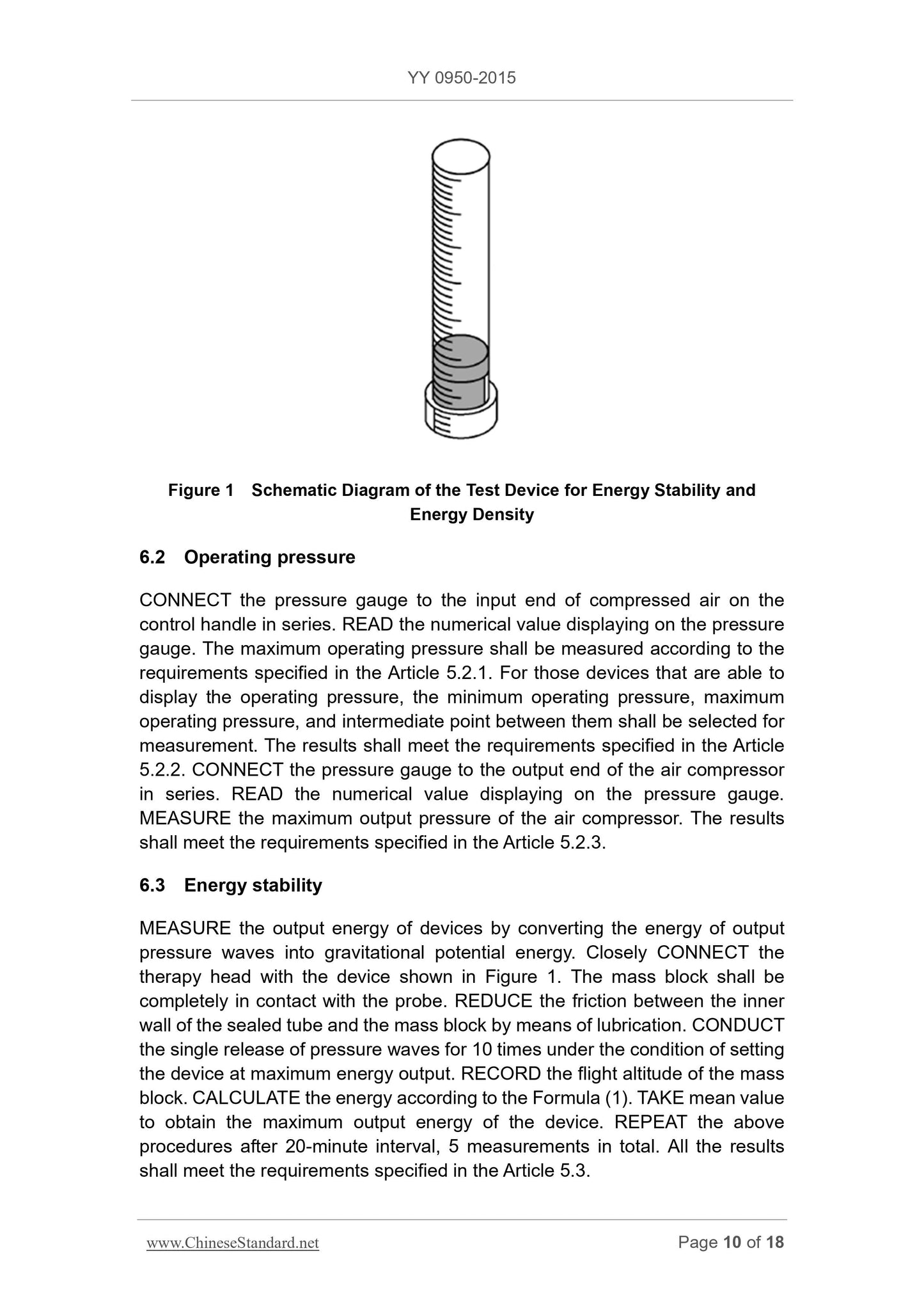
a) energy stability and energy density of the test device. 1, with a scale length of transparent tube, there are mass, transparent tube top
Open section (from security considerations should prevent mass flying stopper).
b) the depth of penetration test. can test device output pressure waves into electrical signals piezoelectric sensor or piezoresistive sensors (if co
Vibration frequency parameter, the parameter is above 50kHz) and display the electrical signal oscilloscope.
c) pipeline pressure resistance test. the ability to provide the requirements of this pressure, and to maintain a predetermined pressure variation does not exceed ± 5% of the gas source, including
Including in the case where the test sample is leaking.
d) pressure gauge (pressure gauge). not less than 0.4.
e) Analog Load. at least two hydrogel pads, the thickness of 15mm ~ 20mm, a diameter of typically 1.2 times the diameter of the treatment head, the Young's modulus
Amount is generally preferably 0.2MPa ~ 0.3MPa.
Figure 1 energy stability and energy density of the test device schematic
6.2 Working pressure
The compressed air pressure gauge in series with the input of the control handle, through the pressure gauge to measure the maximum working pressure shall conform to 5.2.1
Demand; the working pressure can be displayed for the device, select the minimum working pressure, maximum working pressure and an intermediate point between the two measurements, the results should meet
Meets the requirement of 5.2.2; pressure gauge connected in the output of the air compressor, air compressor measured by the maximum output pressure gauge readings,
The results should meet the requirements of 5.2.3.
6.3 energy stability
By transforming the energy output pressure wave is gravitational potential energy method of measuring the energy output device. The treatment head apparatus shown in Fig.
Closely, the mass should be in full contact with the probe, a sealed tube wall should be lubricated to reduce friction with the masses. Set the device at maximum energy
Under the conditions of output to a single release of the pressure wave 10 times, recording the mass flight altitude. (1) calculated using the equation of energy and averaged worthy
Maximum output power of the device. After the interval of 20min, and then repeated for a total of 5 measurements. The results shall comply with 5.3
Claim.
E = m × g × h (1)
Where.
E --- output energy;
Mass m --- the mass (95g recommended quality stainless steel mass, diameter should be slightly smaller than the inner diameter of the transparent tube);
Gravitational acceleration g --- at the trial;
--- Fly height H of the mass.
6.4 energy density
The maximum energy density measurements with a universal measuring the diameter of the treatment of head, calculate the area of the treatment head, the use of formula (2) of the computing device, the result should break
Meets the requirement of 5.4.
ED =
(2)
Where.
The maximum energy density of ED ---;
E --- the maximum output power (see Test Method 6.3);
S --- therapeutic area head.
6.5 penetration depth
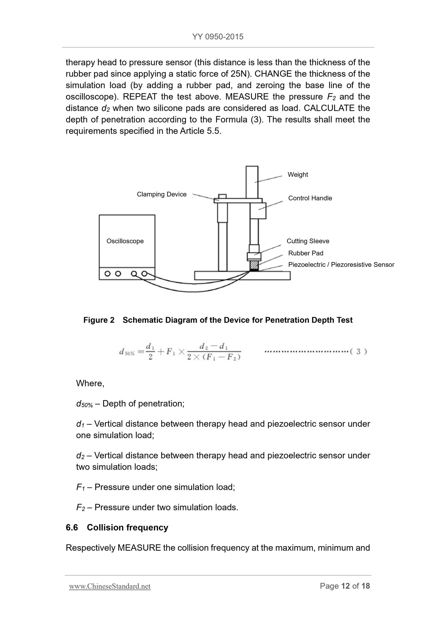
The control handle mounted vertically (upside down treatment), applying a static force of 25N at the top of the control handle (can use about 2.5kg of Fa
Code), the bottom of the treatment head to simulate a load 6.1e), wherein the dummy load is a piezoelectric sensor or directly below the piezoresistive sensors (to connect the oscilloscope
Device). Figure 2 is a schematic diagram of the test apparatus penetration depth. After the device is fixed, the oscilloscope should be zero baseline. So that the device maximum output power
Showing the value of a single release under pressure wave recording oscilloscope and converted to pressure F1, the pressure sensor to measure the treatment of head and vertical distance d1 (the
For applying a static force of 25N, this distance is less than the thickness of the pad). Varying the thickness of dummy load (add a pad, tune the oscilloscope baseline
Zero), repeat the above test. Two measured as a pressure pad of silica gel and the load F2 of the distance d2, by the formula (3) calculate the depth of penetration,
The results should meet the requirements of 5.5.
Figure 2 a schematic view of the depth of penetration test device
d50% =
d1
2 F1 ×
d2-d1
2 × (F1-F2)
(3)
Where.
d50% --- penetration depth;
d1 --- a simulated load, the treatment head to the vertical distance of the piezoelectric sensor;
d2 --- two analog loads, the treatment head to the vertical distance of the piezoelectric sensor.
F1 --- a simulated load under pressure;
F2 --- Two analog pressure under load;
6.6 collision frequency
Select the maximum, minimum and median are three things that the collision frequency measurement. Oscilloscope pressure control solenoid valve is measured knot
Fruit should meet the requirements of 5.6.
6.7 Timers and counters
For timing device with a stopwatch timer measuring the maximum setting value or 30min, whichever is less, shall comply with the timing error 5.7
Requirements. For counting function of the device, the device is set at the maximum collision frequency, measured with a stopwatch 15min or maximum hours of work, take
Smaller, measuring results and the use of 6.6 times the count value is calculated, the result should meet the requirements of 5.7.
6.8 Pulse Width
6.5 pressure waveform during the test oscillosc...
Get Quotation: Click YY 0950-2015 (Self-service in 1-minute)
Historical versions (Master-website): YY 0950-2015
Preview True-PDF (Reload/Scroll-down if blank)
YY 0950-2015: Extracorporeal pressure wave therapy devices by compressed air
YY 0950-2015
Extracorporeal pressure wave therapy devices by compressed air
ICS 11.040.60
C42
People's Republic of China pharmaceutical industry standards
Pneumatic lithotripsy extracorporeal pressure wave treatment device
Issued on. 2015-03-02
2017-01-01 implementation
China Food and Drug Administration released
Foreword
This standard was drafted in accordance with GB/T 1.1-2009 given rules.
The standard safety requirements for full implementation of the GB 9706.1-2007 "Medical Electrical Equipment Part 1. General requirements for safety," the
content.
Please note that some of the content of this document may involve patents. Release mechanism of the present document does not assume responsibility for the identification of these patents.
This standard was proposed by the China Food and Drug Administration.
This standard by the National Technical Committee of Standardization for medical electrical physical therapy equipment at the Technical Committee (SAC/TC10/SC4) centralized.
This standard was drafted. Tianjin, the State Food and Drug Administration Medical Device Quality Supervision and Inspection Center.
The main drafters of this standard. PROCEEDINGS, Sun Huili, Chen Cheng, Wang Ying.
Pneumatic lithotripsy extracorporeal pressure wave treatment device
1 Scope
This standard specifies the pneumatic lithotripsy extracorporeal pressure wave treatment device (hereinafter referred to as the device) terms and definitions, composition, requirements, test side
Method, inspection rules, signs, instructions, packaging, transport and storage.
3.1 This standard applies to equipment regulations.
This standard does not apply to pneumatic ballistic lithotripsy equipment.
2 Normative references
The following documents for the application of this document is essential. For dated references, only the dated version suitable for use herein
Member. For undated references, the latest edition (including any amendments) applies to this document.
GB/T 191-2008 Packaging - Pictorial signs
GB 9706.1-2007 Medical electrical equipment - Part 1. General requirements for safety
GB/T 14710-2009 medical electrical environmental requirements and test methods
GB/T 16886.1 Biological evaluation of medical devices - Part 1. Evaluation of the risk management process and Test
GB/T 16886.5 Biological evaluation of medical devices - Part 5. In vitro cytotoxicity tests
GB/T 16886.10 Biological evaluation of medical devices - Part 10. irritation and delayed-type hypersensitivity test
Corrosion Test Method YY/T 0149-2006 Medical resistant stainless steel
Symbols - Part 1 YY/T 0466.1-2009 medical equipment used with medical device labels, labeling and information. General
Claim
3 Terms and Definitions
GB 9706.1-2007 defined and the following terms and definitions apply to this document.
3.1
Use of compressed air energy generated drive bullet body treatment inside the handle, so that the impact of the bullet body pulsed treatment of head, the use of both elastic
Collision pressure waves, percutaneous device conduction to the painful area of treatment.
3.2
Control handle controlhandle
The operator holds the device, the control body and the treatment of compressed air driven bullet head collisions generate pressure waves.
3.3
Bullet projectile body
Located in the control handle cavity, compressed air driven by elastic collisions with rigid body treatment head.
3.4
Energy converter energytransmitter
Treatment head
Located on the control end of the handle, the contact with the patient's part. Generally rigid material, with the bullet body elastic collisions, the energy transfer
Into a pressure wave in the affected patients.
3.5
Penetration depth depthofpenetration
When the pressure wave through the biological tissue, when the depth of the pressure decayed to 50% at the initial pressure.
4 Composition
Devices typically include. a host control handle (containing bullet body), treatment of head and air compressors (generally included in the host).
5 Requirements
5.1 Working conditions
It shall be specified by the manufacturer. If not specified, shall meet the requirements of GB 9706.1-2007 in Chapter 10.
5.2 Working pressure
5.2.1 The manufacturer shall declare the maximum working pressure of equipment in a random file, the maximum working pressure shall not exceed 600kPa.
5.2.2 The equipment should work pressure display means for displaying the actual value error should not exceed ± 10%.
Air Compressor 5.2.3 1.5 times the maximum output pressure should not exceed the manufacturer's declaration maximum working pressure.
5.3 energy stability
Stability of the pressure wave energy generated by the equipment should be better than ± 20%.
5.4 energy density
The manufacturer shall declare the random file for each device in the treatment of head maximum energy density, the error should not exceed ± 20%.
5.5 penetration depth
The manufacturer shall declare the maximum penetration depth of the device at random file, the error should not exceed ± 20%.
5.6 collision frequency
Bullet body and collision frequency treatment head should be adjustable. Collision frequency error should not exceed ± 10%.
5.7 timer or counter
Equipment should have at least one of the following for a single treatment for counting functions.
a) If the timer device and a display device having a timing error should not exceed ± 5% of the set value.
b) If the equipment has a counter and a display device, counting error should not exceed ± 5% of the set value.
5.8 Pulse Width
The manufacturer shall declare a random file output pulse width of the pressure wave, the error should not exceed ± 10%.
5.9 pressure resistance tubing
Air compressor and pipeline control handle connected devices should be able to withstand the pressure of the air compressor should not be less than the maximum output pressure.
And keeping 1min under this pressure, the pipeline should not be broken, not permanent (plastic) deformation, the connecting pipe joints should not fall off.
5.10 overpressure safety device
5.10.1 The equipment should have overpressure safety device, the safety device should be large enough to release capacity to ensure that when the supply pressure control device
When the failure of the connected system pressure does not exceed 10% of the maximum working pressure.
5.10.2 air compressor should have a pressure relief device, it should meet the requirements in GB 9706.1-2007 requirements of 45.7.
Fatigue Performance 5.11 treatment head
The manufacturer shall declare the life cycle of the equipment (in the number of calculations) in random files and equipment during the entire cycle of output energy density
Shall comply with the requirements of 5.4.
5.12 Corrosion Resistance
The outer surface of the treatment head should have good corrosion resistance. After the corrosion test, should be no traces of corrosion, or by wiping, cleaning that is simple
Slight traces can be removed.
5.13 biocompatibility
5.13.1 Materials
Treatment of head contact with the body of proof should have been made in line with a biocompatible material, or should be prescribed by biological 5.13.2
Compatibility test.
5.13.2 biocompatibility test
5.13.2.1 cytotoxicity test. cytotoxicity should be no more than one stage.
5.13.2.2 skin irritation test. Skin irritation average score is 0 to 0.4, the reaction should be classified as a very slight reaction.
5.13.2.3 sensitization test. There should be no delayed-type hypersensitivity.
5.14 Function
5.14.1 The equipment should have to work pressure, collision frequency, duration of treatment or the number of collisions of the display, set or adjust functions.
5.14.2 insufficient pressure equipment should prompt function.
5.14.3 In addition to counting function device having 5.7 requirements, should also have a separate counter (or counting function) recording bullet body and cure
The total number of collisions treatment head, and the counter can be cleared operated by the manufacturer.
5.15 appearance
The outer surface of the device should be clean and free from mechanical damage, scratches and other defects; tag should be clearly visible, operation and adjustment mechanism should be flexible, reliable, tight
The firmware should be no loose; the screen should display clear, no uneven brightness defects; pipe connectors should be fastened with no loose. Treatment of head and surface should be smooth
Smooth.
5.16 Safety requirements
Equipment shall meet the requirements of GB 9706.1-2007.
5.17 Environmental testing requirements
Environmental testing equipment shall GB/T 14710-2009 regulations.
6 Test methods
6.1 Test Equipment
We recommend the following equipment to or higher than the test apparatus to test the accuracy of the following equipment.
a) energy stability and energy density of the test device. 1, with a scale length of transparent tube, there are mass, transparent tube top
Open section (from security considerations should prevent mass flying stopper).
b) the depth of penetration test. can test device output pressure waves into electrical signals piezoelectric sensor or piezoresistive sensors (if co
Vibration frequency parameter, the parameter is above 50kHz) and display the electrical signal oscilloscope.
c) pipeline pressure resistance test. the ability to provide the requirements of this pressure, and to maintain a predetermined pressure variation does not exceed ± 5% of the gas source, including
Including in the case where the test sample is leaking.
d) pressure gauge (pressure gauge). not less than 0.4.
e) Analog Load. at least two hydrogel pads, the thickness of 15mm ~ 20mm, a diameter of typically 1.2 times the diameter of the treatment head, the Young's modulus
Amount is generally preferably 0.2MPa ~ 0.3MPa.
Figure 1 energy stability and energy density of the test device schematic
6.2 Working pressure
The compressed air pressure gauge in series with the input of the control handle, through the pressure gauge to measure the maximum working pressure shall conform to 5.2.1
Demand; the working pressure can be displayed for the device, select the minimum working pressure, maximum working pressure and an intermediate point between the two measurements, the results should meet
Meets the requirement of 5.2.2; pressure gauge connected in the output of the air compressor, air compressor measured by the maximum output pressure gauge readings,
The results should meet the requirements of 5.2.3.
6.3 energy stability
By transforming the energy output pressure wave is gravitational potential energy method of measuring the energy output device. The treatment head apparatus shown in Fig.
Closely, the mass should be in full contact with the probe, a sealed tube wall should be lubricated to reduce friction with the masses. Set the device at maximum energy
Under the conditions of output to a single release of the pressure wave 10 times, recording the mass flight altitude. (1) calculated using the equation of energy and averaged worthy
Maximum output power of the device. After the interval of 20min, and then repeated for a total of 5 measurements. The results shall comply with 5.3
Claim.
E = m × g × h (1)
Where.
E --- output energy;
Mass m --- the mass (95g recommended quality stainless steel mass, diameter should be slightly smaller than the inner diameter of the transparent tube);
Gravitational acceleration g --- at the trial;
--- Fly height H of the mass.
6.4 energy density
The maximum energy density measurements with a universal measuring the diameter of the treatment of head, calculate the area of the treatment head, the use of formula (2) of the computing device, the result should break
Meets the requirement of 5.4.
ED =
(2)
Where.
The maximum energy density of ED ---;
E --- the maximum output power (see Test Method 6.3);
S --- therapeutic area head.
6.5 penetration depth
The control handle mounted vertically (upside down treatment), applying a static force of 25N at the top of the control handle (can use about 2.5kg of Fa
Code), the bottom of the treatment head to simulate a load 6.1e), wherein the dummy load is a piezoelectric sensor or directly below the piezoresistive sensors (to connect the oscilloscope
Device). Figure 2 is a schematic diagram of the test apparatus penetration depth. After the device is fixed, the oscilloscope should be zero baseline. So that the device maximum output power
Showing the value of a single release under pressure wave recording oscilloscope and converted to pressure F1, the pressure sensor to measure the treatment of head and vertical distance d1 (the
For applying a static force of 25N, this distance is less than the thickness of the pad). Varying the thickness of dummy load (add a pad, tune the oscilloscope baseline
Zero), repeat the above test. Two measured as a pressure pad of silica gel and the load F2 of the distance d2, by the formula (3) calculate the depth of penetration,
The results should meet the requirements of 5.5.
Figure 2 a schematic view of the depth of penetration test device
d50% =
d1
2 F1 ×
d2-d1
2 × (F1-F2)
(3)
Where.
d50% --- penetration depth;
d1 --- a simulated load, the treatment head to the vertical distance of the piezoelectric sensor;
d2 --- two analog loads, the treatment head to the vertical distance of the piezoelectric sensor.
F1 --- a simulated load under pressure;
F2 --- Two analog pressure under load;
6.6 collision frequency
Select the maximum, minimum and median are three things that the collision frequency measurement. Oscilloscope pressure control solenoid valve is measured knot
Fruit should meet the requirements of 5.6.
6.7 Timers and counters
For timing device with a stopwatch timer measuring the maximum setting value or 30min, whichever is less, shall comply with the timing error 5.7
Requirements. For counting function of the device, the device is set at the maximum collision frequency, measured with a stopwatch 15min or maximum hours of work, take
Smaller, measuring results and the use of 6.6 times the count value is calculated, the result should meet the requirements of 5.7.
6.8 Pulse Width
6.5 pressure waveform during the test oscillosc...
Share