1
/
of
12
PayPal, credit cards. Download editable-PDF & invoice in 1 second!
YY 1081-2011 English PDF
YY 1081-2011 English PDF
Regular price
$145.00 USD
Regular price
Sale price
$145.00 USD
Unit price
/
per
Shipping calculated at checkout.
Couldn't load pickup availability
Delivery: 3 seconds. Download true-PDF + Invoice.
Get Quotation: Click YY 1081-2011 (Self-service in 1-minute)
Historical versions (Master-website): YY 1081-2011
Preview True-PDF (Reload/Scroll-down if blank)
YY 1081-2011: Medical endoscopes - Endoscope supply units - Cold light sources
YY 1081-2011
Medical endoscopes-Endoscope supply units-Cold light sources
ICS 11.040.99
C40
People's Republic of China Pharmaceutical Industry Standard
Replacing YY 91081-1999
Medical endoscope
Endoscope function supply device cold light source
2011-12-31 released
2013-06-01 implementation
Issued by the State Food and Drug Administration
Preface
This standard was drafted in accordance with the rules given in GB/T 1.1-2009.
YY 91081-1999 "Cold Light Source for Medical Endoscopes" shall be abolished from the date of implementation of this standard.
Please note that certain contents of this document may involve patents. The issuing agency of this document is not responsible for identifying these patents.
This standard was proposed by the State Food and Drug Administration.
This standard is under the jurisdiction of the National Medical Optics and Instrument Standardization Sub-Technical Committee (SAC/TC103/SC1).
Drafting organizations of this standard. Hangzhou Medical Device Quality Supervision and Inspection Center of the State Food and Drug Administration, Zhejiang Medical Device Inspection
Institute, Hangzhou Haoke Optoelectronic Instrument Co., Ltd.
The main drafters of this standard. Jia Xiaohang, Yan Qinglai, Zhang Weixing, He Tao, Qi Weiming, Chen Shenglai.
The previous versions of the standard replaced by this standard are as follows.
---YY 91081-1999.
Medical endoscope
Endoscope function supply device cold light source
1 Scope
This standard specifies the requirements for cold light sources.
This standard applies to cold light sources used as functional supply devices in endoscopy and surgery. Other cold light sources can be selected according to applicability
use.
2 Normative references
The following documents are indispensable for the application of this document. For dated reference documents, only the dated version applies to this article
For all undated reference documents, the latest version (including all amendments) applies to this document.
GB/T 5702-2003 Light source color rendering evaluation method
GB/T 7922-2008 Method for measuring the color of lighting sources
GB 9706.1-2007 Medical electrical equipment Part 1.General requirements for safety
GB 9706.19-2000 Medical electrical equipment Part 2.Particular requirements for the safety of endoscopic equipment
3 Terms and definitions
The following terms and definitions apply to this document.
3.1
Light input surfaceoftheopticalfibercable
The effective light-transmitting surface of the connecting end of the optical cable and the cold light source.
3.2
Referenceplane
After the cold light source is connected to the adapter cable, the plane coincides with the light entrance surface of the optical cable.
3.3
Reference window referencearea
Located on the reference surface, a circular window with a diameter of D=5mm centered on the center of the light incident surface of the adapter cable.
4 requirements
4.1 Composition
The manufacturer should give the composition of the cold light source in any feasible form, including the characteristics of the applicable bulb, and clarify whether the composition contains
Light guide.
The product provided by the manufacturer should conform to the composition described.
4.2 Spectral performance
4.2.1 Color rendering index
Except for special spectral applications, the cold light source suitable for optical observation glasses should have good color rendering and the color rendering index should not be less than 90.
4.2.2 Correlated color temperature
Except for special spectral uses, it is suitable for cold light sources of optical observation glasses, and the correlated color temperature should be in the range of 3000K to 7000K.
4.2.3 The radiant flux ratio of red, green and blue
For the cold light source that can be used in the camera system, the matching relationship of the spectral response of the corresponding camera system should be given. With 515nm~545nm wavelength
The green light radiant flux ϕeg in the range of
And the nominal value of the ratio of blue light flux ϕeb to ϕeg in the wavelength range of 435nm~465nm, with a tolerance of ±20%.
If the light source claims to be unsuitable for the requirements of the above response section, the distribution and matching ratio of the corresponding response section should be given.
4.2.4 Spectral characteristics of cold light sources for special spectral purposes
For cold light sources for special spectral purposes, the manufacturer shall give the spectral characteristics of the cold light source, including the main peak of the spectrum and the nominal half-width
Value and tolerance. The cold light source should conform to this spectral characteristic.
4.2.5 Infrared cut-off performance
For cold light sources except for special spectral purposes, the ratio of radiant flux to luminous flux in the wavelength range of 300nm~1700nm should not be large
At 6mW/lm.
4.3 Illumination uniformity performance of the reference window
4.3.1 Uniformity of illumination
The manufacturer shall give the nominal value of the light uniformity of the cold light source for the rigid endoscope in the reference window, and the measured value shall not be greater than the nominal value.
1.05 times.
4.3.2 Illumination overrun point
The number of points beyond the limit of illuminance of the cold light source for rigid endoscopes in the reference window should not be greater than 2.
4.4 Radiation performance
4.4.1 Total output luminous flux
The manufacturer should give the nominal value of the total output luminous flux, the tolerance is -10%, and the upper limit is not counted.
4.5 Electrical safety
Should meet the requirements of GB 9706.1-2007 and GB 9706.19-2000.
4.6 Mechanical interface specifications
The manufacturer shall provide the specification of the mechanical interface of the cold light source used to connect the optical cable for lighting, and the cold light source shall meet this specification.
4.7 Safety measures against failure
For cold light sources used in surgery, safety measures should be taken to prevent failures. The method of giving lamp life indication or giving lamp replacement instructions can be adopted.
Style, or use spare bulbs.
5 Test method
5.1 Determination of color rendering index
5.1.1 Device
Spectral radiation measurement system, the spectral measurement range is not less than 380nm~780nm, the wavelength resolution is not more than 1.5nm, relative spectrum
The difference in radiance is not more than 1%.
5.1.2 Procedure
Control the test environment, the dark illumination is not more than 1lx.
The power supply of the control light source remains stable at the nominal voltage value. The voltage should be monitored and the voltage stability should be controlled within ±2%.
The light source should be fully preheated for no less than 30min.
Select the wavelength step of the spectral radiation system to be 5nm.
When the light intensity setting of the cold light source is adjusted to the maximum and the middle value, the relative spectral power distribution S(λ) of the cold light source is measured respectively.
5.1.3 Calculation
It should be carried out in accordance with GB/T 5702-2003 and GB/T 7922-2008.
5.2 Calculation of correlated color temperature
The relative spectral power distribution S(λ) of the cold light source measured in 5.1.2 is calculated according to GB/T 5702-2003 color coordinates u, v,
Then find the corresponding correlated color temperature according to the black body radiation locus in the uv chromaticity coordinate chart.
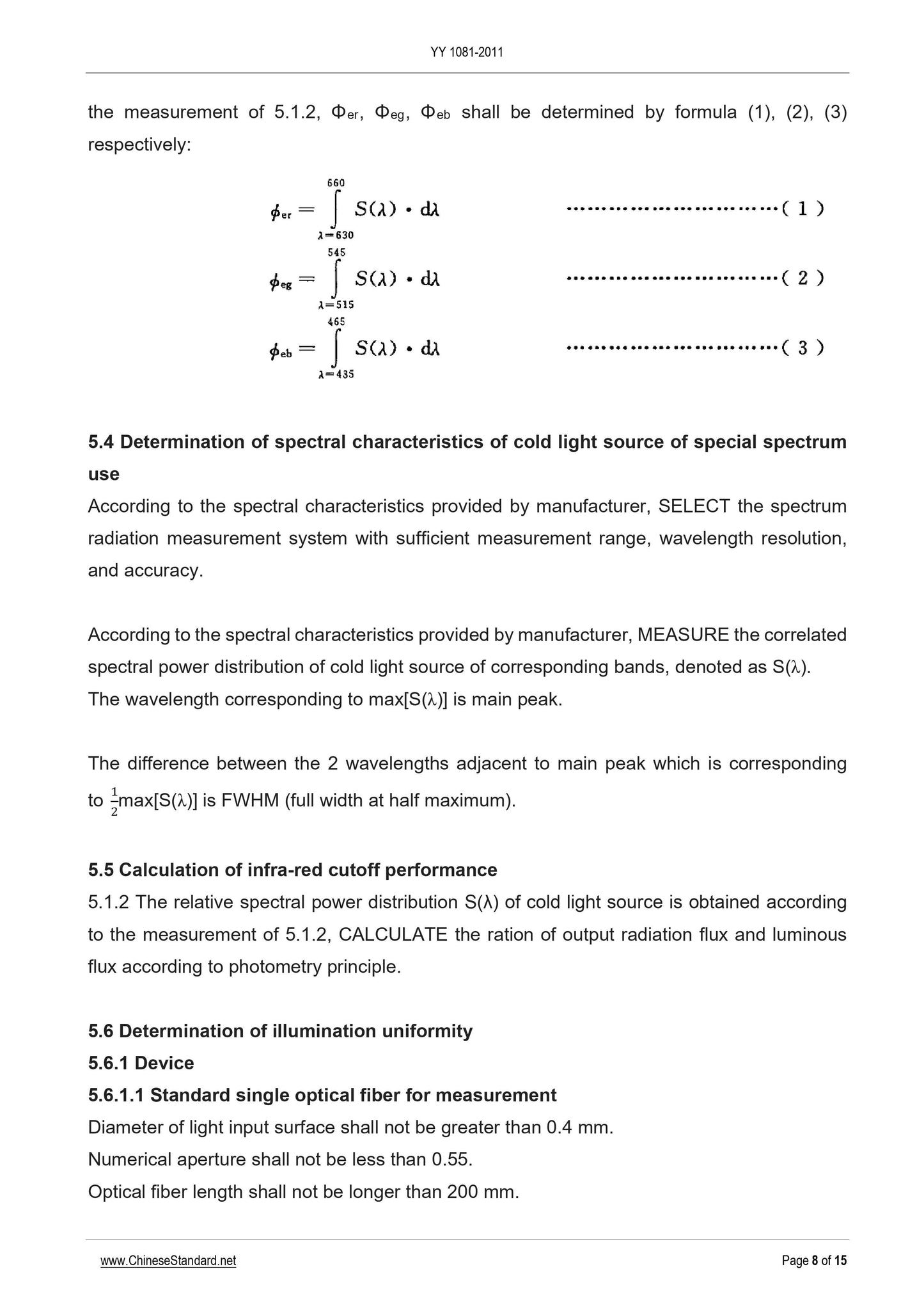
5.3 Calculation of the radiant flux ratio of red, green and blue
According to the relative spectral power distribution S(λ) of the cold light source measured in 5.1.2, ϕer, ϕeg, and ϕeb are respectively represented by equations (1), (2), and (3)
determine.
5.4 Determination of the spectral characteristics of cold light sources for special spectral purposes
According to the spectral characteristics given by the manufacturer, select a spectral radiation measurement system with sufficient measurement range, wavelength resolution and accuracy.
According to the spectral characteristics given by the manufacturer, the relative spectral power distribution of the cold light source in the corresponding band is measured, denoted as S(λ).
The wavelength corresponding to max[S(λ)] is the main peak.
2max
[S(λ)] The difference between the two wavelengths near the main peak corresponding to [S(λ)] is the full width at half maximum.
5.5 Calculation of infrared cut-off performance
The relative spectral power distribution S(λ) of the cold light source measured in 5.1.2 is calculated according to the photometric principle.
The ratio of luminous flux.
5.6 Determination of uniformity of light
5.6.1 Device
5.6.1.1 Standard single fiber for measurement
The diameter of the light incident surface at the light incident end is not greater than 0.4mm.
The numerical aperture is not less than 0.55.
The length of the optical fiber is not more than.200mm.
In the wavelength range of 380nm~780nm, the relative spectral transmittance flatness is not more than ±10%.
The central axis of the single fiber should be perpendicular to the end face of the single fiber.
An aperture should be set after the light exit end, and the aperture angle of the aperture to the center of the light exit end surface of the fiber should be equivalent to the 0.55 numerical aperture.
Note. If different single optical fibers are used for measurement at different measurement positions, the light energy transmission efficiency of each single optical fiber should be corrected to obtain the correction coefficient.
5.6.1.2 Positioning device
The light entrance end of the standard single fiber for measurement can be positioned to ensure that its light entrance surface is located on the reference window of the cold light source and can meet the reference window
The positioning requirements of the measurement location to be selected on the above.
5.6.1.3 Luminous flux meter or equivalent device
The measurement repeatability difference is not more than 1%, and the accuracy level should be equivalent to the secondary illuminance meter that meets the requirements of JB/T 7403-1994.
Measure the luminous flux output from the standard single fiber output end.
5.6.2 Procedure
5.6.2.1 Preparation
Control the test environment, the dark illumination is not more than 1lx.
The power supply for the control test remains stable at the nominal voltage value, the voltage should be monitored, and the voltage stability should be controlled within ±2%.
The light source should be fully preheated for no less than 30min.
Adjust the light intensity setting of the cold light source to maximum.
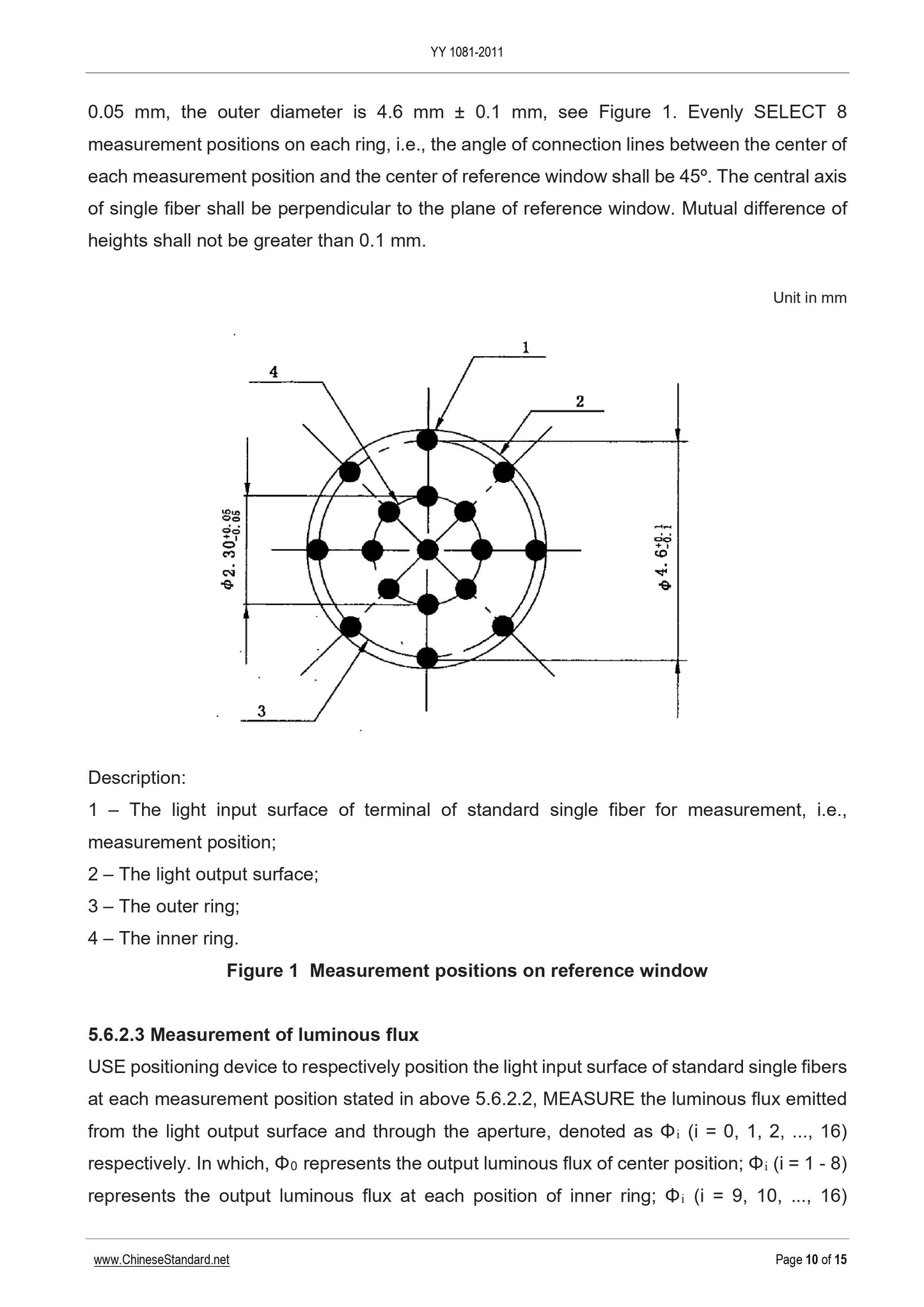
5.6.2.2 Provisions for measurement location
The measurement position on the reference window is shown in Figure 1.The measurement positions are located in the center of the reference window and on the 2 rings respectively. The diameter of the inner ring is
2.3mm±0.05mm, the outer ring diameter is 4.6mm±0.1mm, see Figure 1.8 measurement positions are uniformly selected on each ring, that is, each
The angle between the center of the measurement position and the center of the reference window is 45°. The central axis of the single fiber should be perpendicular to the plane of the reference window.
The difference is not more than 0.1mm.
5.6.2.3 Measuring luminous flux
Use the positioning device to locate the light-incident surface of the standard single optical fiber at each measurement position described in 5.6.2.2, and the measurement standard
The luminous flux output from the light-emitting end of a single fiber after passing through the aperture is denoted as Φi (i=0,1,2,,16). Among them, Φ0 represents the output of the center position
Outgoing luminous flux; Φi (i=1~8) represents the output luminous flux at each position of the inner ring; Φi (i=9,10,,16) represents the output light at each position of the outer ring
Flux.
Note. If different single optical fibers are used for measurement in different measurement positions, the light output of each single optical fiber should be corrected according to the light energy transmission efficiency of each single optical fiber.
The luminous flux output from the terminal is corrected.
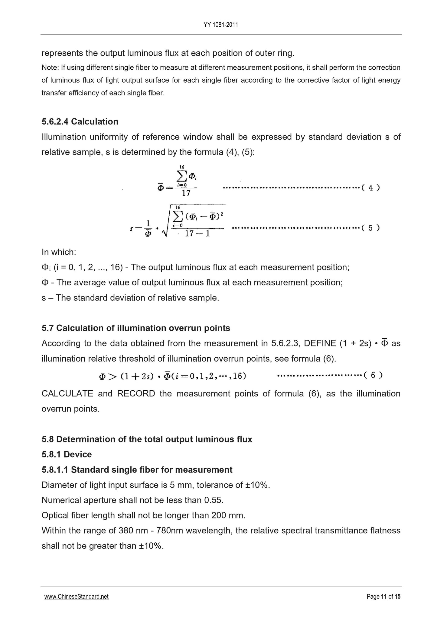
5.6.2.4 Calculation
The illumination uniformity of the reference window is expressed by the relative sample standard deviation s, and s is determined by equations (4) and (5).
i=
5.7 Calculation of the number of points beyond the limit of illuminance
Calculate and record the number of measurement points in formula (6) as the number of points beyond the limit of illuminance.
5.8 Determination of total output luminous flux
5.8.1 Device
5.8.1.1 Standard single fiber for measurement
The diameter of the light incident surface at the light incident end is 5mm, with a tolerance of ±10%.
The numerical aperture is not less than 0.55.
The length of the optical fiber is not more than.200mm.
In the wavelength range of 380nm~780nm, the relative spectral transmittance flatness is not more than ±10%.
The central axis of the single fiber should be perpendicular to the end face of the single fiber.
Known light energy transfer efficiency k, the measurement of light energy transfer efficiency k is carried out in accordance with Appendix A.
5.8.1.2 Positioning device
The light entrance end of the standard single optical fiber for measurement can be positioned to ensure that its light entrance surface is positioned on the reference window of the cold light source, and it is placed in the light entrance surface
The center coincides with the center of the reference window of the cold light source, and the center axis is perpendicular to the plane of the reference window.
5.8.1.3 Luminous flux meter or equivalent device
The measurement repeatability difference is not more than 1%, and the accuracy level should be equivalent to the secondary illuminance meter that meets the requirements of JB/T 7403-1994.
Measure the luminous flux output from the standard single fiber end.
5.8.2 Procedure
5.8.2.1 Preparation
Control the test environment, the dark illumination is not more than 1lx.
The power supply for the contro...
Get Quotation: Click YY 1081-2011 (Self-service in 1-minute)
Historical versions (Master-website): YY 1081-2011
Preview True-PDF (Reload/Scroll-down if blank)
YY 1081-2011: Medical endoscopes - Endoscope supply units - Cold light sources
YY 1081-2011
Medical endoscopes-Endoscope supply units-Cold light sources
ICS 11.040.99
C40
People's Republic of China Pharmaceutical Industry Standard
Replacing YY 91081-1999
Medical endoscope
Endoscope function supply device cold light source
2011-12-31 released
2013-06-01 implementation
Issued by the State Food and Drug Administration
Preface
This standard was drafted in accordance with the rules given in GB/T 1.1-2009.
YY 91081-1999 "Cold Light Source for Medical Endoscopes" shall be abolished from the date of implementation of this standard.
Please note that certain contents of this document may involve patents. The issuing agency of this document is not responsible for identifying these patents.
This standard was proposed by the State Food and Drug Administration.
This standard is under the jurisdiction of the National Medical Optics and Instrument Standardization Sub-Technical Committee (SAC/TC103/SC1).
Drafting organizations of this standard. Hangzhou Medical Device Quality Supervision and Inspection Center of the State Food and Drug Administration, Zhejiang Medical Device Inspection
Institute, Hangzhou Haoke Optoelectronic Instrument Co., Ltd.
The main drafters of this standard. Jia Xiaohang, Yan Qinglai, Zhang Weixing, He Tao, Qi Weiming, Chen Shenglai.
The previous versions of the standard replaced by this standard are as follows.
---YY 91081-1999.
Medical endoscope
Endoscope function supply device cold light source
1 Scope
This standard specifies the requirements for cold light sources.
This standard applies to cold light sources used as functional supply devices in endoscopy and surgery. Other cold light sources can be selected according to applicability
use.
2 Normative references
The following documents are indispensable for the application of this document. For dated reference documents, only the dated version applies to this article
For all undated reference documents, the latest version (including all amendments) applies to this document.
GB/T 5702-2003 Light source color rendering evaluation method
GB/T 7922-2008 Method for measuring the color of lighting sources
GB 9706.1-2007 Medical electrical equipment Part 1.General requirements for safety
GB 9706.19-2000 Medical electrical equipment Part 2.Particular requirements for the safety of endoscopic equipment
3 Terms and definitions
The following terms and definitions apply to this document.
3.1
Light input surfaceoftheopticalfibercable
The effective light-transmitting surface of the connecting end of the optical cable and the cold light source.
3.2
Referenceplane
After the cold light source is connected to the adapter cable, the plane coincides with the light entrance surface of the optical cable.
3.3
Reference window referencearea
Located on the reference surface, a circular window with a diameter of D=5mm centered on the center of the light incident surface of the adapter cable.
4 requirements
4.1 Composition
The manufacturer should give the composition of the cold light source in any feasible form, including the characteristics of the applicable bulb, and clarify whether the composition contains
Light guide.
The product provided by the manufacturer should conform to the composition described.
4.2 Spectral performance
4.2.1 Color rendering index
Except for special spectral applications, the cold light source suitable for optical observation glasses should have good color rendering and the color rendering index should not be less than 90.
4.2.2 Correlated color temperature
Except for special spectral uses, it is suitable for cold light sources of optical observation glasses, and the correlated color temperature should be in the range of 3000K to 7000K.
4.2.3 The radiant flux ratio of red, green and blue
For the cold light source that can be used in the camera system, the matching relationship of the spectral response of the corresponding camera system should be given. With 515nm~545nm wavelength
The green light radiant flux ϕeg in the range of
And the nominal value of the ratio of blue light flux ϕeb to ϕeg in the wavelength range of 435nm~465nm, with a tolerance of ±20%.
If the light source claims to be unsuitable for the requirements of the above response section, the distribution and matching ratio of the corresponding response section should be given.
4.2.4 Spectral characteristics of cold light sources for special spectral purposes
For cold light sources for special spectral purposes, the manufacturer shall give the spectral characteristics of the cold light source, including the main peak of the spectrum and the nominal half-width
Value and tolerance. The cold light source should conform to this spectral characteristic.
4.2.5 Infrared cut-off performance
For cold light sources except for special spectral purposes, the ratio of radiant flux to luminous flux in the wavelength range of 300nm~1700nm should not be large
At 6mW/lm.
4.3 Illumination uniformity performance of the reference window
4.3.1 Uniformity of illumination
The manufacturer shall give the nominal value of the light uniformity of the cold light source for the rigid endoscope in the reference window, and the measured value shall not be greater than the nominal value.
1.05 times.
4.3.2 Illumination overrun point
The number of points beyond the limit of illuminance of the cold light source for rigid endoscopes in the reference window should not be greater than 2.
4.4 Radiation performance
4.4.1 Total output luminous flux
The manufacturer should give the nominal value of the total output luminous flux, the tolerance is -10%, and the upper limit is not counted.
4.5 Electrical safety
Should meet the requirements of GB 9706.1-2007 and GB 9706.19-2000.
4.6 Mechanical interface specifications
The manufacturer shall provide the specification of the mechanical interface of the cold light source used to connect the optical cable for lighting, and the cold light source shall meet this specification.
4.7 Safety measures against failure
For cold light sources used in surgery, safety measures should be taken to prevent failures. The method of giving lamp life indication or giving lamp replacement instructions can be adopted.
Style, or use spare bulbs.
5 Test method
5.1 Determination of color rendering index
5.1.1 Device
Spectral radiation measurement system, the spectral measurement range is not less than 380nm~780nm, the wavelength resolution is not more than 1.5nm, relative spectrum
The difference in radiance is not more than 1%.
5.1.2 Procedure
Control the test environment, the dark illumination is not more than 1lx.
The power supply of the control light source remains stable at the nominal voltage value. The voltage should be monitored and the voltage stability should be controlled within ±2%.
The light source should be fully preheated for no less than 30min.
Select the wavelength step of the spectral radiation system to be 5nm.
When the light intensity setting of the cold light source is adjusted to the maximum and the middle value, the relative spectral power distribution S(λ) of the cold light source is measured respectively.
5.1.3 Calculation
It should be carried out in accordance with GB/T 5702-2003 and GB/T 7922-2008.
5.2 Calculation of correlated color temperature
The relative spectral power distribution S(λ) of the cold light source measured in 5.1.2 is calculated according to GB/T 5702-2003 color coordinates u, v,
Then find the corresponding correlated color temperature according to the black body radiation locus in the uv chromaticity coordinate chart.
5.3 Calculation of the radiant flux ratio of red, green and blue
According to the relative spectral power distribution S(λ) of the cold light source measured in 5.1.2, ϕer, ϕeg, and ϕeb are respectively represented by equations (1), (2), and (3)
determine.
5.4 Determination of the spectral characteristics of cold light sources for special spectral purposes
According to the spectral characteristics given by the manufacturer, select a spectral radiation measurement system with sufficient measurement range, wavelength resolution and accuracy.
According to the spectral characteristics given by the manufacturer, the relative spectral power distribution of the cold light source in the corresponding band is measured, denoted as S(λ).
The wavelength corresponding to max[S(λ)] is the main peak.
2max
[S(λ)] The difference between the two wavelengths near the main peak corresponding to [S(λ)] is the full width at half maximum.
5.5 Calculation of infrared cut-off performance
The relative spectral power distribution S(λ) of the cold light source measured in 5.1.2 is calculated according to the photometric principle.
The ratio of luminous flux.
5.6 Determination of uniformity of light
5.6.1 Device
5.6.1.1 Standard single fiber for measurement
The diameter of the light incident surface at the light incident end is not greater than 0.4mm.
The numerical aperture is not less than 0.55.
The length of the optical fiber is not more than.200mm.
In the wavelength range of 380nm~780nm, the relative spectral transmittance flatness is not more than ±10%.
The central axis of the single fiber should be perpendicular to the end face of the single fiber.
An aperture should be set after the light exit end, and the aperture angle of the aperture to the center of the light exit end surface of the fiber should be equivalent to the 0.55 numerical aperture.
Note. If different single optical fibers are used for measurement at different measurement positions, the light energy transmission efficiency of each single optical fiber should be corrected to obtain the correction coefficient.
5.6.1.2 Positioning device
The light entrance end of the standard single fiber for measurement can be positioned to ensure that its light entrance surface is located on the reference window of the cold light source and can meet the reference window
The positioning requirements of the measurement location to be selected on the above.
5.6.1.3 Luminous flux meter or equivalent device
The measurement repeatability difference is not more than 1%, and the accuracy level should be equivalent to the secondary illuminance meter that meets the requirements of JB/T 7403-1994.
Measure the luminous flux output from the standard single fiber output end.
5.6.2 Procedure
5.6.2.1 Preparation
Control the test environment, the dark illumination is not more than 1lx.
The power supply for the control test remains stable at the nominal voltage value, the voltage should be monitored, and the voltage stability should be controlled within ±2%.
The light source should be fully preheated for no less than 30min.
Adjust the light intensity setting of the cold light source to maximum.
5.6.2.2 Provisions for measurement location
The measurement position on the reference window is shown in Figure 1.The measurement positions are located in the center of the reference window and on the 2 rings respectively. The diameter of the inner ring is
2.3mm±0.05mm, the outer ring diameter is 4.6mm±0.1mm, see Figure 1.8 measurement positions are uniformly selected on each ring, that is, each
The angle between the center of the measurement position and the center of the reference window is 45°. The central axis of the single fiber should be perpendicular to the plane of the reference window.
The difference is not more than 0.1mm.
5.6.2.3 Measuring luminous flux
Use the positioning device to locate the light-incident surface of the standard single optical fiber at each measurement position described in 5.6.2.2, and the measurement standard
The luminous flux output from the light-emitting end of a single fiber after passing through the aperture is denoted as Φi (i=0,1,2,,16). Among them, Φ0 represents the output of the center position
Outgoing luminous flux; Φi (i=1~8) represents the output luminous flux at each position of the inner ring; Φi (i=9,10,,16) represents the output light at each position of the outer ring
Flux.
Note. If different single optical fibers are used for measurement in different measurement positions, the light output of each single optical fiber should be corrected according to the light energy transmission efficiency of each single optical fiber.
The luminous flux output from the terminal is corrected.
5.6.2.4 Calculation
The illumination uniformity of the reference window is expressed by the relative sample standard deviation s, and s is determined by equations (4) and (5).
i=
5.7 Calculation of the number of points beyond the limit of illuminance
Calculate and record the number of measurement points in formula (6) as the number of points beyond the limit of illuminance.
5.8 Determination of total output luminous flux
5.8.1 Device
5.8.1.1 Standard single fiber for measurement
The diameter of the light incident surface at the light incident end is 5mm, with a tolerance of ±10%.
The numerical aperture is not less than 0.55.
The length of the optical fiber is not more than.200mm.
In the wavelength range of 380nm~780nm, the relative spectral transmittance flatness is not more than ±10%.
The central axis of the single fiber should be perpendicular to the end face of the single fiber.
Known light energy transfer efficiency k, the measurement of light energy transfer efficiency k is carried out in accordance with Appendix A.
5.8.1.2 Positioning device
The light entrance end of the standard single optical fiber for measurement can be positioned to ensure that its light entrance surface is positioned on the reference window of the cold light source, and it is placed in the light entrance surface
The center coincides with the center of the reference window of the cold light source, and the center axis is perpendicular to the plane of the reference window.
5.8.1.3 Luminous flux meter or equivalent device
The measurement repeatability difference is not more than 1%, and the accuracy level should be equivalent to the secondary illuminance meter that meets the requirements of JB/T 7403-1994.
Measure the luminous flux output from the standard single fiber end.
5.8.2 Procedure
5.8.2.1 Preparation
Control the test environment, the dark illumination is not more than 1lx.
The power supply for the contro...
Share