1
/
of
12
PayPal, credit cards. Download editable-PDF & invoice in 1 second!
YY/T 0119.1-2014 English PDF (YYT0119.1-2014)
YY/T 0119.1-2014 English PDF (YYT0119.1-2014)
Regular price
$230.00 USD
Regular price
Sale price
$230.00 USD
Unit price
/
per
Shipping calculated at checkout.
Couldn't load pickup availability
Delivery: 3 seconds. Download true-PDF + Invoice.
Get Quotation: Click YY/T 0119.1-2014 (Self-service in 1-minute)
Historical versions (Master-website): YY/T 0119.1-2014
Preview True-PDF (Reload/Scroll-down if blank)
YY/T 0119.1-2014: Spinal implants. Components used in the surgical fixation of the spinal skeletal system. Part 1: General requirements
YY/T 0119.1-2014
Spinal implants.Components used in the surgical fixation of the spinal skeletal system.Part 1.General requirements
ICS 11.040.40
C35
People's Republic of China Pharmaceutical Industry Standards
Partially replace YY 0119-2002, YY 0120-2002
Spinal implant spinal fixation
System components part 1.general requirements
Released on.2014-06-17
2015-07-01 implementation
Issued by the State Food and Drug Administration
Table of contents
Foreword Ⅰ
Introduction Ⅱ
1 Scope 1
2 Normative references 1
3 Terms and definitions 1
4 Significance and application 5
5 Material 6
6 Requirements 6
7 Manufacturing 6
8 Sterilization 6
9 Packaging 6
10 Information provided by the manufacturer 6
Appendix A (informative appendix) Basic principles 8
Appendix B (informative appendix) List of approved method standards for chemical analysis 9
Reference 10
Spinal implant spinal fixation
System components part 1.general requirements
1 Scope
This part of YY/T 0119 specifies the general terms used to describe the dimensions and other physical characteristics of the spinal internal fixation system.
The material, manufacturing, sterilization, packaging, and information provided by the manufacturer of the spinal internal fixation system components are specified.
2 Normative references
The following documents are indispensable for the application of this document. For dated reference documents, only the dated version applies to this article
Pieces. For undated reference documents, the latest version (including all amendments) is applicable to this document.
GB 4234 Stainless steel for surgical implants
GB/T 10623 Terminology for Mechanical Properties Test of Metallic Materials
GB/T 13810 Titanium and titanium alloy processed materials for surgical implants
GB/T 16825.1 Inspection of static uniaxial testing machine Part 1.Inspection and test of force measuring system of tensile and (or) compression testing machine
calibration
GB 23102 Surgical implant metal material Ti-6Al-7Nb alloy processing material
YY/T 0119.2-2014 Spinal implant spinal internal fixation system components Part 2.Metal spinal screws
YY/T 0119.3-2014 Spinal implant spinal internal fixation system components Part 3.Metal spinal plate
YY/T 0119.4-2014 Spinal implants spinal internal fixation system components Part 4.Metal spinal rods
YY/T 0640-2008 General requirements for passive surgical implants
YY/T 0857 Spinal implant test method in vertebral body resection model
YY/T 0961 Static and fatigue performance evaluation method of spinal implant components and connecting devices
ISO 5832-2 Surgical implant metal materials Part 2.Pure titanium (Implantsforsurgery-Metalicmaterials-
Part 2.Unaloyedtitanium)
ISO 5832-3 Surgical implant metal materials Part 3.Forged titanium-6 aluminum-4 vanadium alloy (Implantsforsurgery-
Metalicmaterials-Part 3.Wroughttitanium6-aluminium4-vanadiumaloy)
ASTMF382 standard requirements and test methods for metal bone plates (SpecificationandTestMethodforMetalic
BonePlates)
ASTMF543 Standard requirements and test methods for medical metal bone screws (SpecificationandTestMethodsfor
MetalicMedicalBoneScrews)
ASTMF1582 and spinal implant related terms (TerminologyRelatingtoSpinalImplants)
3 Terms and definitions
Defined by GB/T 10623, YY/T 0857, YY/T 0961, ASTMF382, ASTMF543, ASTMF1582 and the following
The listed terms and definitions apply to this document.
3.1
Expansionheadscrew
The head can be elastically deformed, and it is a threaded anchor that is mechanically connected to other spine structural elements.
3.2
Locking screw
A threaded anchor rigidly connected to the longitudinal elements in the spinal structure.
3.3
Self-locking screw
The threaded anchor is deformed at the end of the screwing process, so as to be locked with the matched spine structural element.
3.4
Shaftscrew
A threaded anchor whose thread diameter is equal to the diameter of its non-threaded rod.
3.5
Rod diameter
The chord length through the center of the rod's cross section.
Note. Expressed in millimeters (mm).
3.6
Rodlength
The total length between the ends of the rod.
Note. Expressed in millimeters (mm).
3.7
0.2% residual displacement 0.2% offsetdisplacement
During the test, a residual displacement equivalent to 0.002 times the test gauge length was generated.
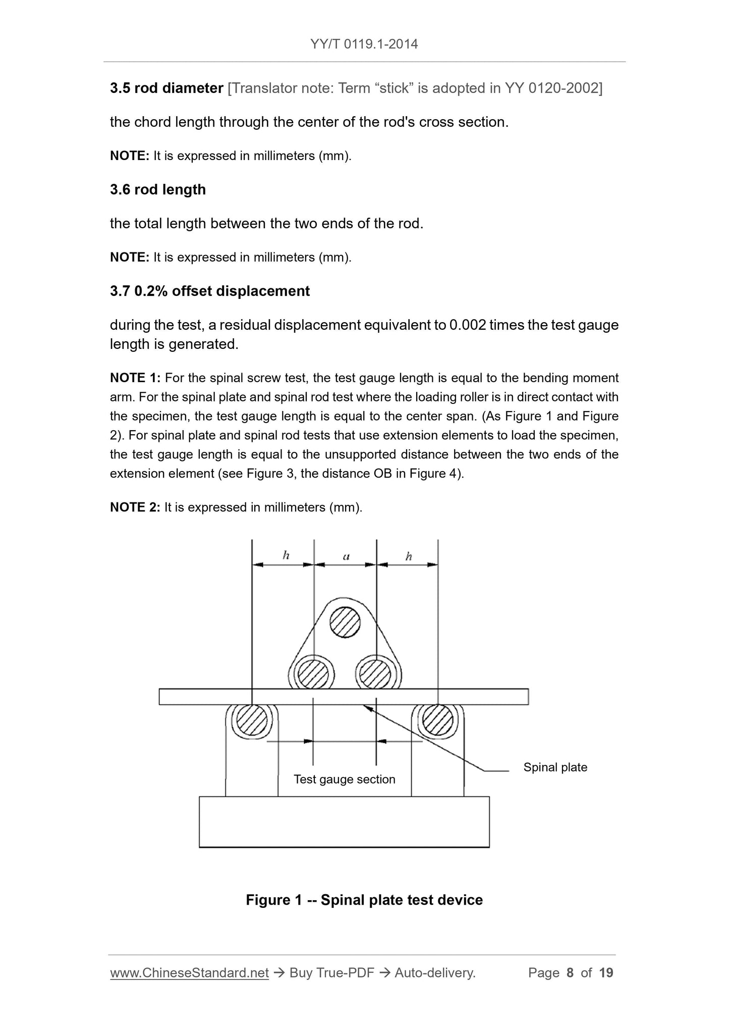
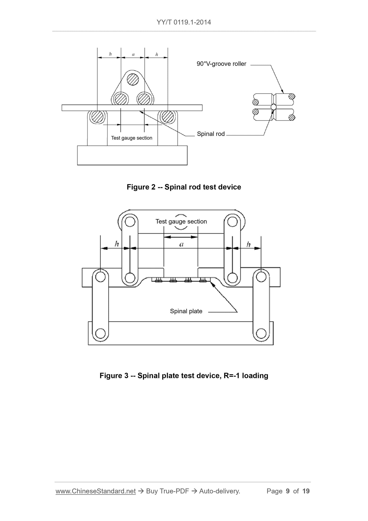
Note 1.For the spinal screw test, the test gauge length is equal to the bending moment arm. For the spinal plate and spinal rod test where the loading roller is in direct contact with the specimen, the test
The gauge length is equal to the center span. (Figure 1 and Figure 2). For spinal plate and spinal rod tests that use extension elements to load the specimen, the test gauge length
The length is equal to the unsupported distance between the two ends of the extension element (as shown in Figure 3, the distance OB in Figure 4).
Note 2.Expressed in millimeters (mm).
3.9
Fatigue end bending moment bendingfatiguerunoutmoment
Under the specified R ratio, all samples of the spine component will not fail after 2.5×10⁶ loading cycles.
Bending moment.
Note. It is expressed in Newton meters (N·m).
3.10
Bending moment arm
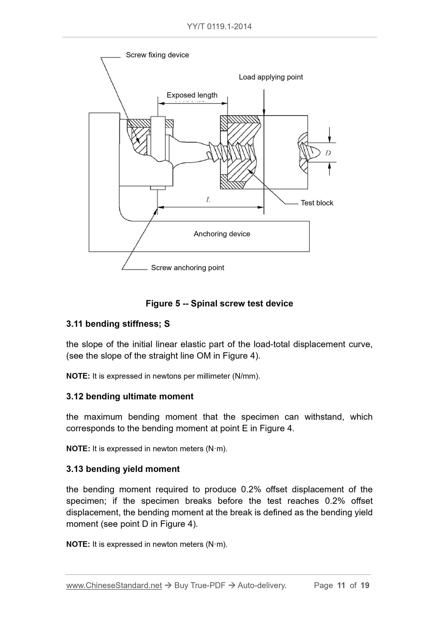
Before the component is deformed, the distance between the line of action of the applied force and the clamping point of the specimen (usually the axis of the longitudinal element) (see Figure 5)
的size L).
Note. Expressed in millimeters (mm).
3.11
Bending stiffness
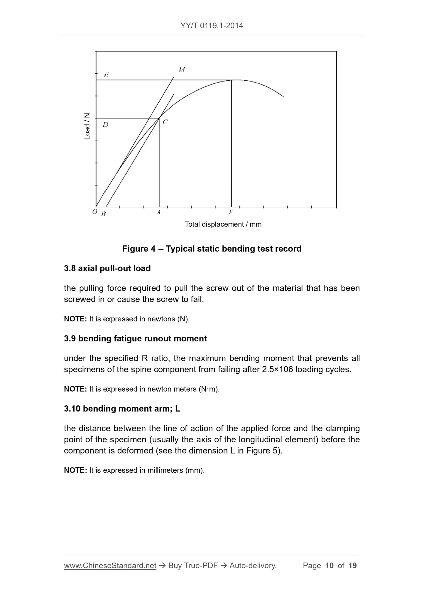
The slope of the initial linear elastic part of the load-total displacement curve, (see the slope of the line OM in Figure 4).
Note. It is expressed in cattle per millimeter (N/mm).
3.12
Ultimate bending moment
The maximum bending moment that the specimen can withstand, which corresponds to the bending moment at point E in Figure 4.
Note. It is expressed in Newton meters (N·m).
3.13
Bending yield moment
The bending moment required to produce 0.2% residual displacement of the specimen. If the sample breaks before the test reaches 0.2% residual displacement, the
The bending moment at fracture is defined as the yield bending moment (see point D in Figure 4).
Note. It is expressed in Newton meters (N·m).
3.14
Exposedlength
The linear distance between the surface of the test block where the screw is embedded and the screw anchoring position on the test fixture (usually the axis of the longitudinal element)
(See Figure 5).
Note. Expressed in millimeters (mm).
3.15
Grossfailure
Residual displacement caused by fracture or plastic deformation that exceeds the yield displacement and can lead to failure of spinal components.
3.16
Insertiondepth
The linear distance between the position of the screw in the test block and its position on the outer surface of the test block before the test.
Note. Expressed in millimeters (mm).
3.17
Median fatigue bending moment after N cycles medianbendingfatiguemomentatNcycles
Under the specified R ratio, 50% of the samples in a given sample can be expected to withstand the maximum bending moment of N loading cycles.
Note. It is expressed in Newton meters (N·m).
3.18
Permanent displacement
When the load is removed, the total displacement remaining on the test sample.
3.19
Yield torque
The torque applied when the screw reaches its proportional limit.
Note 1.The value is measured by the offset method, and the offset angle is 2°.
Note 2.It is expressed in Newton meters (N·m).
3.20
Total displacement
The zero load intercept of the loading point relative to the initial linear part of the load-displacement curve (see point O in Figure 4) moves in the loading direction
Moving distance.
Note. Expressed in millimeters (mm).
3.21
Yield displacement
The total displacement corresponding to the bending yield strength (distance OA in Figure 4).
Note. Expressed in millimeters (mm).
4 Significance and application
4.1 The spinal implant system usually consists of several components. Screws, plates, and rods are part of many spinal implant structures. These ministries
The piece is designed to transfer loads between the bone and the longitudinal and/or transverse elements. This part makes provisions for these components and defines standards, etc.
Effectiveness test method, used to evaluate different types of components.
4.2 Since the loading method of the spine components in the body may be different from the loading method of the loading device explained in this section, use this section
The results obtained in the sub-test may not be able to predict the in vivo performance of the component or structure as a whole. However, these tests can be used to compare different types
The mechanical properties of the type components.
4.3 The mechanical characteristics related to the performance of the spinal components measured in this section can be used to predict similar functions and indications, but different types.
Mechanical properties of components.
5 materials
5.1 The manufacturer is responsible for ensuring that the materials used to manufacture spinal components are suitable for implantation in the human body. The suitability of the material can be in accordance with YY/T 0640
Method for verification.
5.2 When choosing a material, the manufacturer should also consider the materials of other components in the spinal implant structure. Not in the spinal implant structure
When mixed with materials, unacceptable corrosion should be prevented.
5.3 Some materials that have been used as spinal components are given below.
---Pure titanium (ISO 5832-2);
---Ti-6Al-4V alloy (ISO 5832-3);
---Stainless steel (see GB 4234);
---Ti-6Al-7Nb alloy (see GB 23102).
6 requirements
6.1 Metal spine screws
Should meet the requirements of YY/T 0119.2-2014.
6.2 Metal spine board
Should meet the requirements of YY/T 0119.3-2014.
6.3 Metal spine rod
Should meet the requirements of YY/T 0119.4-2014.
7 Manufacturing
It should meet the requirements of Chapter 8 of YY/T 0640-2008.
8 Sterilization
It should meet the requirements of Chapter 9 of YY/T 0640-2008.
9 Packaging
It should meet the requirements of Chapter 10 of YY/T 0640-2008.
10 Information provided by the manufacturer
10.1 Marks on spinal components
Should comply with the provisions of Chapter 11 of YY/T 0640-2008, and include the following information.
---Material.
10.2 Label
Should comply with YY/T 0640-2008 Chapter 11, and include the following information.
---Material;
---Sterilization state.
10.3 Manual
It should meet the requirements of Chapter 11 of YY/T 0640-2008.
Appendix A
(Informative appendix)
Fundamental
A.1 This section aims to provide practical and unified information related to the application of terminology, performance, test methods, and the application of spinal structural components.
interest. This section provides the geometric definition, size, classification and terminology, material and performance definitions of spine structural components.
A.2 Surgeons should have the ability to select spinal instruments suitable for the indications of patients with indications. To achieve this, the doctor should be sure that the implant
The naming of the size and its supporting tools has specific and recognized meanings, no matter what the manufacturer or type is different, these namings can be measured
And reliable. Regardless of the manufacturer or type, the mechanics and material properties should also be described in a reliable and recognized way.
In order to ensure the consistency of naming, the terminology, size, mechanics and material properties used should be standardized.
A.3 Since the current level of knowledge is not enough to predict the effects of specific spinal implant types and assembly components, this section is not intended to be used.
To define the performance level of spinal implants.
A.4 This section includes test methods for evaluating static and dynamic mechanical properties of spinal components used as anchoring elements or longitudinal elements in spinal structures.
Law. Spinal implants are used to provide short-term stable fixation during arthrodesis. This section does not involve long-term mechanical issues of spinal components.
The question does not involve the performance of non-fusion spinal implants.
A.5 One of the purposes of this section is to provide a consistent standard test method for evaluating the spine at a meaningful number of cycles.
The fatigue strength of the piece. It is generally believed that the average time for bone fusion is about 12 months, during which the implant undergoes about 1×10⁶ in the body.
2.5×10⁶ cycles. If the number of cycles is doubled from 2.5×10⁶ times to 5×10⁶ times, the safety factor can be improved, but in fact only
It increases the cost of testing and does not provide more meaningful data. Even if the failure occurs in the 2.5×10⁶~5×10⁶ cycle area
It also usually occurs below the horizontal part of the curve and does not significantly affect the curve itself. Therefore, take 2.5×10⁶ times as a loop
End limit.
A.6 Simulated body fluids or saline may affect the relative performance of the tested spinal components. The performance tests specified in this section are specifically for experiments
Room room temperature conditions, thereby reducing the difference in results. Researchers can also consider more evaluations of simulated body fluids, saline or water to study
The influence of environmental factors.
Get Quotation: Click YY/T 0119.1-2014 (Self-service in 1-minute)
Historical versions (Master-website): YY/T 0119.1-2014
Preview True-PDF (Reload/Scroll-down if blank)
YY/T 0119.1-2014: Spinal implants. Components used in the surgical fixation of the spinal skeletal system. Part 1: General requirements
YY/T 0119.1-2014
Spinal implants.Components used in the surgical fixation of the spinal skeletal system.Part 1.General requirements
ICS 11.040.40
C35
People's Republic of China Pharmaceutical Industry Standards
Partially replace YY 0119-2002, YY 0120-2002
Spinal implant spinal fixation
System components part 1.general requirements
Released on.2014-06-17
2015-07-01 implementation
Issued by the State Food and Drug Administration
Table of contents
Foreword Ⅰ
Introduction Ⅱ
1 Scope 1
2 Normative references 1
3 Terms and definitions 1
4 Significance and application 5
5 Material 6
6 Requirements 6
7 Manufacturing 6
8 Sterilization 6
9 Packaging 6
10 Information provided by the manufacturer 6
Appendix A (informative appendix) Basic principles 8
Appendix B (informative appendix) List of approved method standards for chemical analysis 9
Reference 10
Spinal implant spinal fixation
System components part 1.general requirements
1 Scope
This part of YY/T 0119 specifies the general terms used to describe the dimensions and other physical characteristics of the spinal internal fixation system.
The material, manufacturing, sterilization, packaging, and information provided by the manufacturer of the spinal internal fixation system components are specified.
2 Normative references
The following documents are indispensable for the application of this document. For dated reference documents, only the dated version applies to this article
Pieces. For undated reference documents, the latest version (including all amendments) is applicable to this document.
GB 4234 Stainless steel for surgical implants
GB/T 10623 Terminology for Mechanical Properties Test of Metallic Materials
GB/T 13810 Titanium and titanium alloy processed materials for surgical implants
GB/T 16825.1 Inspection of static uniaxial testing machine Part 1.Inspection and test of force measuring system of tensile and (or) compression testing machine
calibration
GB 23102 Surgical implant metal material Ti-6Al-7Nb alloy processing material
YY/T 0119.2-2014 Spinal implant spinal internal fixation system components Part 2.Metal spinal screws
YY/T 0119.3-2014 Spinal implant spinal internal fixation system components Part 3.Metal spinal plate
YY/T 0119.4-2014 Spinal implants spinal internal fixation system components Part 4.Metal spinal rods
YY/T 0640-2008 General requirements for passive surgical implants
YY/T 0857 Spinal implant test method in vertebral body resection model
YY/T 0961 Static and fatigue performance evaluation method of spinal implant components and connecting devices
ISO 5832-2 Surgical implant metal materials Part 2.Pure titanium (Implantsforsurgery-Metalicmaterials-
Part 2.Unaloyedtitanium)
ISO 5832-3 Surgical implant metal materials Part 3.Forged titanium-6 aluminum-4 vanadium alloy (Implantsforsurgery-
Metalicmaterials-Part 3.Wroughttitanium6-aluminium4-vanadiumaloy)
ASTMF382 standard requirements and test methods for metal bone plates (SpecificationandTestMethodforMetalic
BonePlates)
ASTMF543 Standard requirements and test methods for medical metal bone screws (SpecificationandTestMethodsfor
MetalicMedicalBoneScrews)
ASTMF1582 and spinal implant related terms (TerminologyRelatingtoSpinalImplants)
3 Terms and definitions
Defined by GB/T 10623, YY/T 0857, YY/T 0961, ASTMF382, ASTMF543, ASTMF1582 and the following
The listed terms and definitions apply to this document.
3.1
Expansionheadscrew
The head can be elastically deformed, and it is a threaded anchor that is mechanically connected to other spine structural elements.
3.2
Locking screw
A threaded anchor rigidly connected to the longitudinal elements in the spinal structure.
3.3
Self-locking screw
The threaded anchor is deformed at the end of the screwing process, so as to be locked with the matched spine structural element.
3.4
Shaftscrew
A threaded anchor whose thread diameter is equal to the diameter of its non-threaded rod.
3.5
Rod diameter
The chord length through the center of the rod's cross section.
Note. Expressed in millimeters (mm).
3.6
Rodlength
The total length between the ends of the rod.
Note. Expressed in millimeters (mm).
3.7
0.2% residual displacement 0.2% offsetdisplacement
During the test, a residual displacement equivalent to 0.002 times the test gauge length was generated.
Note 1.For the spinal screw test, the test gauge length is equal to the bending moment arm. For the spinal plate and spinal rod test where the loading roller is in direct contact with the specimen, the test
The gauge length is equal to the center span. (Figure 1 and Figure 2). For spinal plate and spinal rod tests that use extension elements to load the specimen, the test gauge length
The length is equal to the unsupported distance between the two ends of the extension element (as shown in Figure 3, the distance OB in Figure 4).
Note 2.Expressed in millimeters (mm).
3.9
Fatigue end bending moment bendingfatiguerunoutmoment
Under the specified R ratio, all samples of the spine component will not fail after 2.5×10⁶ loading cycles.
Bending moment.
Note. It is expressed in Newton meters (N·m).
3.10
Bending moment arm
Before the component is deformed, the distance between the line of action of the applied force and the clamping point of the specimen (usually the axis of the longitudinal element) (see Figure 5)
的size L).
Note. Expressed in millimeters (mm).
3.11
Bending stiffness
The slope of the initial linear elastic part of the load-total displacement curve, (see the slope of the line OM in Figure 4).
Note. It is expressed in cattle per millimeter (N/mm).
3.12
Ultimate bending moment
The maximum bending moment that the specimen can withstand, which corresponds to the bending moment at point E in Figure 4.
Note. It is expressed in Newton meters (N·m).
3.13
Bending yield moment
The bending moment required to produce 0.2% residual displacement of the specimen. If the sample breaks before the test reaches 0.2% residual displacement, the
The bending moment at fracture is defined as the yield bending moment (see point D in Figure 4).
Note. It is expressed in Newton meters (N·m).
3.14
Exposedlength
The linear distance between the surface of the test block where the screw is embedded and the screw anchoring position on the test fixture (usually the axis of the longitudinal element)
(See Figure 5).
Note. Expressed in millimeters (mm).
3.15
Grossfailure
Residual displacement caused by fracture or plastic deformation that exceeds the yield displacement and can lead to failure of spinal components.
3.16
Insertiondepth
The linear distance between the position of the screw in the test block and its position on the outer surface of the test block before the test.
Note. Expressed in millimeters (mm).
3.17
Median fatigue bending moment after N cycles medianbendingfatiguemomentatNcycles
Under the specified R ratio, 50% of the samples in a given sample can be expected to withstand the maximum bending moment of N loading cycles.
Note. It is expressed in Newton meters (N·m).
3.18
Permanent displacement
When the load is removed, the total displacement remaining on the test sample.
3.19
Yield torque
The torque applied when the screw reaches its proportional limit.
Note 1.The value is measured by the offset method, and the offset angle is 2°.
Note 2.It is expressed in Newton meters (N·m).
3.20
Total displacement
The zero load intercept of the loading point relative to the initial linear part of the load-displacement curve (see point O in Figure 4) moves in the loading direction
Moving distance.
Note. Expressed in millimeters (mm).
3.21
Yield displacement
The total displacement corresponding to the bending yield strength (distance OA in Figure 4).
Note. Expressed in millimeters (mm).
4 Significance and application
4.1 The spinal implant system usually consists of several components. Screws, plates, and rods are part of many spinal implant structures. These ministries
The piece is designed to transfer loads between the bone and the longitudinal and/or transverse elements. This part makes provisions for these components and defines standards, etc.
Effectiveness test method, used to evaluate different types of components.
4.2 Since the loading method of the spine components in the body may be different from the loading method of the loading device explained in this section, use this section
The results obtained in the sub-test may not be able to predict the in vivo performance of the component or structure as a whole. However, these tests can be used to compare different types
The mechanical properties of the type components.
4.3 The mechanical characteristics related to the performance of the spinal components measured in this section can be used to predict similar functions and indications, but different types.
Mechanical properties of components.
5 materials
5.1 The manufacturer is responsible for ensuring that the materials used to manufacture spinal components are suitable for implantation in the human body. The suitability of the material can be in accordance with YY/T 0640
Method for verification.
5.2 When choosing a material, the manufacturer should also consider the materials of other components in the spinal implant structure. Not in the spinal implant structure
When mixed with materials, unacceptable corrosion should be prevented.
5.3 Some materials that have been used as spinal components are given below.
---Pure titanium (ISO 5832-2);
---Ti-6Al-4V alloy (ISO 5832-3);
---Stainless steel (see GB 4234);
---Ti-6Al-7Nb alloy (see GB 23102).
6 requirements
6.1 Metal spine screws
Should meet the requirements of YY/T 0119.2-2014.
6.2 Metal spine board
Should meet the requirements of YY/T 0119.3-2014.
6.3 Metal spine rod
Should meet the requirements of YY/T 0119.4-2014.
7 Manufacturing
It should meet the requirements of Chapter 8 of YY/T 0640-2008.
8 Sterilization
It should meet the requirements of Chapter 9 of YY/T 0640-2008.
9 Packaging
It should meet the requirements of Chapter 10 of YY/T 0640-2008.
10 Information provided by the manufacturer
10.1 Marks on spinal components
Should comply with the provisions of Chapter 11 of YY/T 0640-2008, and include the following information.
---Material.
10.2 Label
Should comply with YY/T 0640-2008 Chapter 11, and include the following information.
---Material;
---Sterilization state.
10.3 Manual
It should meet the requirements of Chapter 11 of YY/T 0640-2008.
Appendix A
(Informative appendix)
Fundamental
A.1 This section aims to provide practical and unified information related to the application of terminology, performance, test methods, and the application of spinal structural components.
interest. This section provides the geometric definition, size, classification and terminology, material and performance definitions of spine structural components.
A.2 Surgeons should have the ability to select spinal instruments suitable for the indications of patients with indications. To achieve this, the doctor should be sure that the implant
The naming of the size and its supporting tools has specific and recognized meanings, no matter what the manufacturer or type is different, these namings can be measured
And reliable. Regardless of the manufacturer or type, the mechanics and material properties should also be described in a reliable and recognized way.
In order to ensure the consistency of naming, the terminology, size, mechanics and material properties used should be standardized.
A.3 Since the current level of knowledge is not enough to predict the effects of specific spinal implant types and assembly components, this section is not intended to be used.
To define the performance level of spinal implants.
A.4 This section includes test methods for evaluating static and dynamic mechanical properties of spinal components used as anchoring elements or longitudinal elements in spinal structures.
Law. Spinal implants are used to provide short-term stable fixation during arthrodesis. This section does not involve long-term mechanical issues of spinal components.
The question does not involve the performance of non-fusion spinal implants.
A.5 One of the purposes of this section is to provide a consistent standard test method for evaluating the spine at a meaningful number of cycles.
The fatigue strength of the piece. It is generally believed that the average time for bone fusion is about 12 months, during which the implant undergoes about 1×10⁶ in the body.
2.5×10⁶ cycles. If the number of cycles is doubled from 2.5×10⁶ times to 5×10⁶ times, the safety factor can be improved, but in fact only
It increases the cost of testing and does not provide more meaningful data. Even if the failure occurs in the 2.5×10⁶~5×10⁶ cycle area
It also usually occurs below the horizontal part of the curve and does not significantly affect the curve itself. Therefore, take 2.5×10⁶ times as a loop
End limit.
A.6 Simulated body fluids or saline may affect the relative performance of the tested spinal components. The performance tests specified in this section are specifically for experiments
Room room temperature conditions, thereby reducing the difference in results. Researchers can also consider more evaluations of simulated body fluids, saline or water to study
The influence of environmental factors.
Share