1
/
of
12
PayPal, credit cards. Download editable-PDF & invoice in 1 second!
YY/T 0681.13-2014 English PDF (YY/T0681.13-2014)
YY/T 0681.13-2014 English PDF (YY/T0681.13-2014)
Regular price
$175.00 USD
Regular price
Sale price
$175.00 USD
Unit price
/
per
Shipping calculated at checkout.
Couldn't load pickup availability
Delivery: 3 seconds. Download true-PDF + Invoice.
Get Quotation: Click YY/T 0681.13-2014 (Self-service in 1-minute)
Historical versions (Master-website): YY/T 0681.13-2014
Preview True-PDF (Reload/Scroll-down if blank)
YY/T 0681.13-2014: Test methods for sterile medical device package. Part 13: Slow rate penetration resistance of flexible barrier films and laminates
YY/T 0681.13-2014
Test methods for sterile medical device package.Part 13. Slow rate penetration resistance of flexible barrier films and laminates
ICS 11.080.040
C31
People's Republic of China Pharmaceutical Industry Standard
Test methods for sterile medical device packaging
Part 13. Flexible barrier films and composite films
Resistance to slow puncture
Part 13. Slowratepenetrationresistanceofflexiblebarrierfilmsandlaminates
2014-06-17 release
2015-07-01 Implementation
Published by the State Food and Drug Administration
Foreword
YY/T 0681 `` Test method for packaging of sterile medical devices ' is divided into the following parts.
--- Part 1. Guidelines for accelerated aging tests;
--- Part 2. Seal strength of soft barrier materials;
--- Part 3. Unrestrained packaging resistance to internal pressure damage;
--- Part 4. Determination of leaking seals in breathable packaging by the penetrating dyeing method;
--- Part 5. Detection of coarse leaks by internal pressure method (bubble method);
--- Part 6. Evaluation of chemical resistance of printing inks and coatings on flexible packaging materials;
--- Part 7. Evaluation of the adhesion of printing ink or coating on flexible packaging materials with tape;
--- Part 8. Determination of the weight of the coated layer;
--- Part 9. Bursting test of the flexible package sealing by air pressure method inside the restraint plate;
--- Part 10. Grading test of microbial barrier against breathable packaging materials;
--- Part 11. visual inspection of medical packaging seal integrity;
--- Part 12. Soft barrier film rub resistance;
--- Part 13. Soft barrier film and composite film resistance to slow penetration.
This part is Part 13 of YY/T 0681.
This section is drafted in accordance with the rules given in GB/T 1.1-2009.
This section is formulated with reference to ASTMF1306-1990 "Slow Puncture Resistance of Flexible Barrier Films and Composite Films".
Please note that some elements of this document may involve patents. The issuer of this document is not responsible for identifying these patents.
This section is under the jurisdiction of the National Technical Committee for Standardization of Medical Infusion Devices (SAC/TC106).
This section was drafted. Shandong Medical Device Product Quality Inspection Center.
This section participated in the drafting unit. Shandong Xinhua Medical Devices Co., Ltd.
The main drafters of this section. Zhang Jing, Dong Dandan, Chen Fang, Yu Xiaohui, Wang Hongmin.
Test methods for sterile medical device packaging
Part 13. Flexible barrier films and composite films
Resistance to slow puncture
1 Scope
This part of YY/T 0681 is suitable for measuring the puncture resistance of the flexible barrier film and the composite film anti-drive probe. This test starts at room temperature.
A biaxial stress is applied to the material at a constant test rate until puncture occurs, and the force, energy, and elongation before perforation are measured.
Note. Appendix A gives the precision and bias of the test methods specified in this section.
2 Normative references
The following documents are essential for the application of this document. For dated references, only the dated version applies to this article
Pieces. For undated references, the latest version (including all amendments) applies to this document.
GB/T 2918 Standard environment for conditioning and testing of plastic specimens (GB/T 2918-1998, idt ISO 291..1997)
3 Terminology
The following terms and definitions apply to this document.
3.1
Elongation
The elastic/plastic deformation of the driving probe when it penetrates the flexible film.
3.2
Puncture resistance
The flexible membrane is capable of withstanding the ability to drive the probe to stretch and/or penetrate.
3.3
Perforation
Formation of visible cracks across the barrier film during piercing.
3.4
Probe penetration depth probepenetration
The moving distance of the probe from contact with the film to the momentary decrease in load when observed on a universal tester recorder.
3.5
Penetrate puncture
The flexible membrane showed brittle elastic failure after being punctured by the driving probe.
4 Significance and application
The puncture resistance of the film is an important end-use property, and sharp-edged products will destroy the integrity of the barrier packaging. This will make gas, odor
And harmful contamination into and out of the package, resulting in product damage and reduced shelf life. The puncture resistance of a material is affected by many factors, such as
Film thickness, modulus of elasticity, penetration rate, temperature, shape and type of probe, etc. Therefore, the penetration of the material can be observed with this method.
The stretch response was quantified. Although a combination of experimental factors can be designed and used to simulate a specific end application,
The recommended conditions of the method should be followed in order to make the materials comparable.
5 instruments
5.1 Universal testing machine with recording device.
5.2 Pressure sensor.
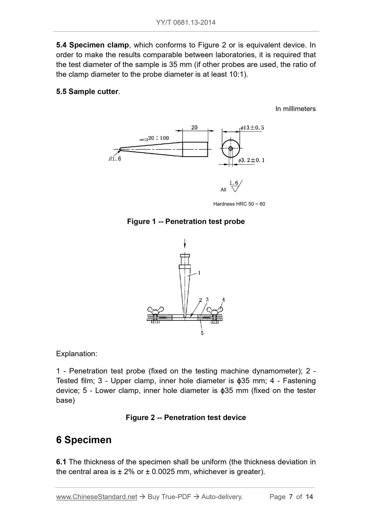
5.3 Puncture test probe, in accordance with Figure 1. For general applications, a hemispherical probe with a diameter of 3.2mm (biaxial stress) is recommended to make the material
Laboratory results are comparable by standard.
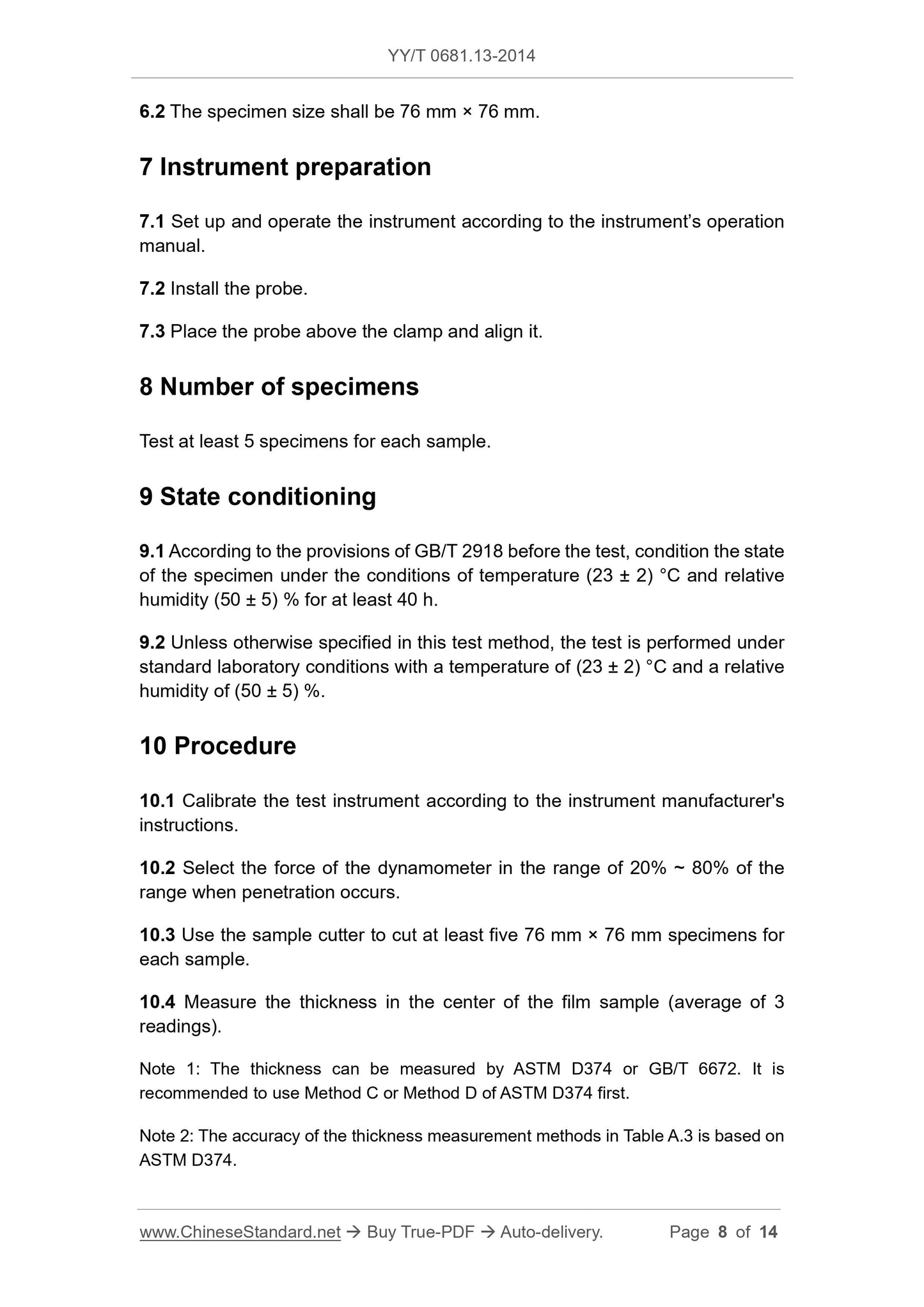
5.4 Specimen holder, conform to Figure 2 or equivalent device. In order to make the results comparable between laboratories, the test diameter of the sample is required to be 35mm
(If using other probes, the ratio of fixture diameter to probe diameter is at least 10. 1).
5.5 Sample cutter.
In millimeters
Figure 1 Puncture test probe
Explanation.
1 --- pierce test probe (fixed on the test machine force gauge);
2 --- test film;
3--upper fixture, inner hole diameter is ϕ35mm;
4--fastening device;
5 --- The lower fixture, the inner hole diameter is ϕ35mm (fixed on the tester abutment).
Figure 2 Penetration test device
6 sample
6.1 The thickness of the sample shall be uniform (the thickness deviation in the central area is ± 2% or ± 0.0025mm, whichever is greater).
6.2 The sample size shall be 76mm × 76mm.
7 Instrument preparation
7.1 Set up and operate the instrument according to the instrument operation manual.
7.2 Install the probe.
7.3 Place the probe above and center it.
8 Number of samples
Test at least 5 specimens for each sample.
9 State adjustment
9.1 Before the test, according to GB/T 2918, adjust the state of the sample at a temperature of (23 ± 2) ° C and a relative humidity of (50 ± 5)%.
Festival at least 40h.
9.2 Unless otherwise specified in this test method, the test is performed at standard laboratory conditions at a temperature of (23 ± 2) ° C and a relative humidity of (50 ± 5)%
Carry on.
10 Procedure
10.1 Calibrate the test instrument according to the instrument manufacturer's instructions.
10.2 Select the force of the dynamometer in the range of 20% ~ 80% of the range when penetration occurs.
10.3 Use a sample cutter to cut at least 5 specimens of 76mm × 76mm for each sample.
10.4 Measure the thickness in the center of the film sample (mean of 3 readings).
Note 1. Thickness can be measured by ASTMD374 or GB/T 6672, and it is recommended to use Method C or Method D of ASTMD374 first.
Note 2. The accuracy of the thickness measurement methods in Table A.3 is based on ASTM D374.
10.5 Adjust the moving speed of the testing machine to 25mm/min.
10.6 Clamp the film sample in the fixture, place the fixture under the probe, align the probe with the center of the film sample, and move it down as much as possible, but not with it
Phase contact.
10.7 Set appropriate stop and return bits for the test machine and clear the data acquisition device to zero, if appropriate.
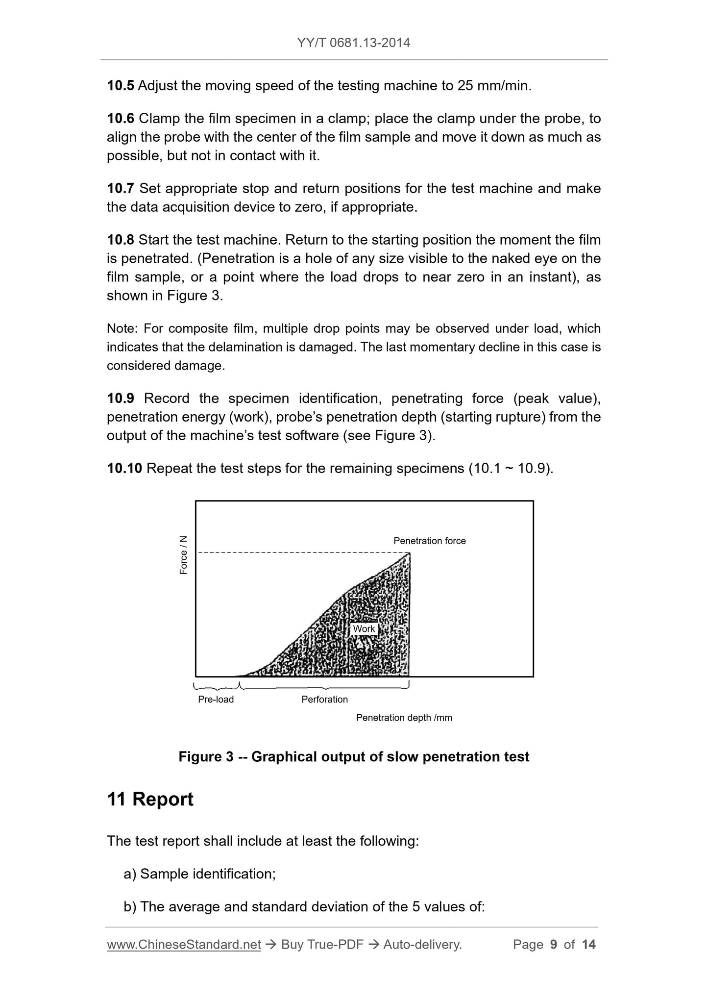
10.8 Start the test machine. Return to the starting position the moment the membrane is punctured. (A puncture is a hole of any size visible to the naked eye on a membrane sample, or
The load momentarily drops to a point near zero), see Figure 3.
Note. For composite membranes, multiple drop points may be observed under load, which indicates that the delamination is damaged. The last instant drop in this case is
Think of destruction.
10.9 Record the sample identification, penetration (peak), penetration energy (work), and probe penetration depth (beginning to break) from the machine test software output
(See Figure 3).
10.10 Repeat the test steps for the remaining samples (10.1 ~ 10.9).
Figure 3 Graphical output of slow puncture test
11 Report
The test report should include at least the following.
a) sample identification;
b) The mean and standard deviation of the five values of.
--- Penetration (N);
--- Penetration energy (J);
--- Probe depth (mm);
--- Thickness (3 values) (mm) of each sample film sample.
Appendix A
(Informative appendix)
Precision and bias
A.1 Precision
A.1.1 Precision data
Table A.1 and Table A.2 were performed by ASTM in 6 laboratories in 1988 ~ 1989 on 6 materials according to ASTME691.
Findings of a collaborative laboratory test. All samples of each material are from the same source, but the samples are in each of the participating experiments
Prepared in the chamber. Each test result is an independently measured test value. Each laboratory obtains 5 test results for each material. each
The laboratory conducts two parallel tests on each material, and treats them as independent materials.
Tables A.3 and A.4 are based on the collaborative experiments of the above laboratories. when using it
It should be noted that the amount of data is relatively small.
Note. The following (A.1.2) explanations of r and R are only intended to give the concept of the approximate precision of this test method. Tables A.1 and A.3 should not be used strictly
Acceptance or rejection of materials, as these data are only for materials that participate in verification and do not represent other batches, conditions, materials, or laboratories. This test party
Users of the method should obtain data for specific laboratories and materials or between specific laboratories. An explanation of these data is given in A.1.2.
A.1.2 Concepts of r and R
A.1.2.1 If Sr is obtained from enough data, the same material is obtained by the same operator, using the same equipment and on the same day
The difference between the two test results exceeds the repeatability limit (r) of the material, and it should be judged that the two test results are not equal.
A.1.2.2 If the SR is obtained from sufficient data, different operators, different equipment, and
The two test results obtained in the laboratory exceed the reproducibility limit (R) of the material, and it should be determined that the two test results are not equal.
A.1.2.3 According to A.1.2.1 and A.1.2.2, the correct probability is about 95% (0.95).
A.2 Bias
There are no accepted standards for estimating the bias of this test method.
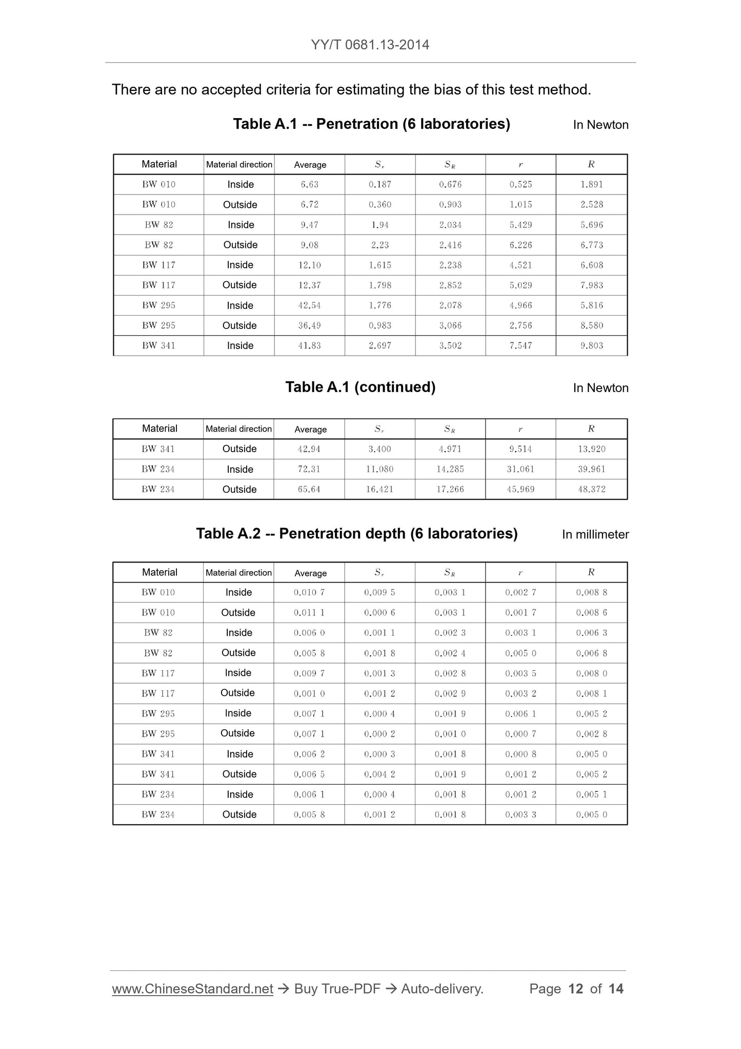
Table A.1 Penetration (6 laboratories) Unit is Newton
Material material direction mean Sr SR r R
BW010 Inner 6.63 0.187 0.676 0.525 1.891
BW010 outer 6.72 0.360 0.903 1.015 2.528
BW82 inside 9.47 1.94 2.034 5.429 5.696
BW82 outside 9.08 2.23 2.416 6.226 6.773
BW117 inside 12.10 1.615 2.238 4.521 6.608
BW117 outside 12.37 1.798 2.852 5.029 7.983
BW295 inner 42.54 1.776 2.078 4.966 5.816
BW295 outside 36.49 0.983 3.066 2.756 8.580
BW341 inside 41.83 2.697 3.502 7.547 9.803
Table A.1 (continued) Unit is Newton
Material material direction mean Sr SR r R
BW341 outside 42.94 3.400 4.971 9.514 13.920
BW234 inside 72.31 11.080 14.285 31.061 39.961
BW234 65.64 16.421 17.266 45.969 48.372
Table A.2 Penetration depth (6 laboratories) Unit is mm
Material material direction mean Sr SR r R
BW010 Inside 0.0107 0.0095 0.0031 0.0027 0.0088
BW010 outside 0.0111 0.0006 0.0031 0.0017 0.0086
BW82 inside 0.0060 0.0011 0.0023 0.0031 0.0063
BW82 outside 0.0058 0.0018 0.0024 0.0050 0.0068
BW117 inside 0.0097 0.0013 0.0028 0.0035 0.0080
BW117 outside 0.0010 0.0012 0.0029 0.0032 0.0081
BW295 inside 0.0071 0.0004 0.0019 0.0061 0.0052
BW295 outside 0.0071 0.0002 0.0010 0.0007 0.0028
BW341 inside 0.0062 0.0003 0.0018 0.0008 0.0050
BW341 outside 0.0065 0.0042 0.0019 0.0012 0.0052
BW234 inside 0.0061 0.0004 0.0018 0.0012 0.0051
BW234 outside 0.0058 0.0012 0.0018 0.0033 0.0050
Table A.3 Material thickness (3 laboratories) Unit is mm
Material material direction mean Sr SR r R
BW010 Inside 0.050 0.0011 0.0012 0.0030 0.0034
BW010 outside 0.049 0.0019 0.0026 0.0052 0.0074
BW82 inside 0.020 0.0006 0.0008 0.0018 0.0023
BW82 outside 0.020 0.0009 0.0015 0.0025 0.0043
BW117 inside 0.013 0.0009 0.0010 0.0025 0.0028
BW117 outside 0.012 0.0012 0.0012 0.0032 0.0034
BW295 inside 0.113 0.0024 0.0029 0.0069 0.0080
BW295 outside 0.113 0.0018 0.0024 0.0050 0.0034
BW341 inside 0.031 0.0015 0.0015 0.0042 0.0042
BW341 outside 0.031 0.0019 0.0024 0.0053 0.0068
BW234 inside 0.210 0.0168 0.0168 0.0470 0.0470
BW234 outside 0.211 0.0160 0.0207 0.0047 0.0579
Table A.4 Penetration energy (4 laboratories) Unit is Joule
Material material direction mean Sr SR r R
BW010 inside 0.0490 0.0042 0.0101 0.0118 0.0292
BW010 outside 0.0502 0.0039 0.0071 0.0109 0.0197
BW82 inside 0.0270 0.0104 0.0115 0.0290 0.0323
BW82 outside 0.0268 0.0091 0.0123 0.0254 0.0343
BW117 inside 0.0599 0.0143 0.0166 0.0379 0.0464
BW117 outside 0.0597 0.0176 0.0242 0.0494 0.0679
BW295 inside 0.1374 0.0111 0.0111 0.0311 0.0311
BW295 outside 0.0926 0.0172 0.0258 0.0481 0.0722
BW341 inside 0.1077 0.0113 0.0178 0.0317 0.0500
BW341 outside 0.1177 0.0125 0.0232 0.0348 0.0649
BW234 inside 0.1839 0.0384 0.0503 0.1074 0.1158
BW234 outside 0.1459 0.0465 0.0586 0.1302 0.1642
references
[1] GB/T 6672 Determination of plastic film and sheet thickness by mechanical measurement
[2] ASTMD374 StandardTestMethods forThicknessofSolidElectricalInsulation
[3] ASTME691 PracticeforConductinganInterlaboratoryStudytoDeterminethePrecision
ofaTestMethod
4102-
31 1860
T /
Get Quotation: Click YY/T 0681.13-2014 (Self-service in 1-minute)
Historical versions (Master-website): YY/T 0681.13-2014
Preview True-PDF (Reload/Scroll-down if blank)
YY/T 0681.13-2014: Test methods for sterile medical device package. Part 13: Slow rate penetration resistance of flexible barrier films and laminates
YY/T 0681.13-2014
Test methods for sterile medical device package.Part 13. Slow rate penetration resistance of flexible barrier films and laminates
ICS 11.080.040
C31
People's Republic of China Pharmaceutical Industry Standard
Test methods for sterile medical device packaging
Part 13. Flexible barrier films and composite films
Resistance to slow puncture
Part 13. Slowratepenetrationresistanceofflexiblebarrierfilmsandlaminates
2014-06-17 release
2015-07-01 Implementation
Published by the State Food and Drug Administration
Foreword
YY/T 0681 `` Test method for packaging of sterile medical devices ' is divided into the following parts.
--- Part 1. Guidelines for accelerated aging tests;
--- Part 2. Seal strength of soft barrier materials;
--- Part 3. Unrestrained packaging resistance to internal pressure damage;
--- Part 4. Determination of leaking seals in breathable packaging by the penetrating dyeing method;
--- Part 5. Detection of coarse leaks by internal pressure method (bubble method);
--- Part 6. Evaluation of chemical resistance of printing inks and coatings on flexible packaging materials;
--- Part 7. Evaluation of the adhesion of printing ink or coating on flexible packaging materials with tape;
--- Part 8. Determination of the weight of the coated layer;
--- Part 9. Bursting test of the flexible package sealing by air pressure method inside the restraint plate;
--- Part 10. Grading test of microbial barrier against breathable packaging materials;
--- Part 11. visual inspection of medical packaging seal integrity;
--- Part 12. Soft barrier film rub resistance;
--- Part 13. Soft barrier film and composite film resistance to slow penetration.
This part is Part 13 of YY/T 0681.
This section is drafted in accordance with the rules given in GB/T 1.1-2009.
This section is formulated with reference to ASTMF1306-1990 "Slow Puncture Resistance of Flexible Barrier Films and Composite Films".
Please note that some elements of this document may involve patents. The issuer of this document is not responsible for identifying these patents.
This section is under the jurisdiction of the National Technical Committee for Standardization of Medical Infusion Devices (SAC/TC106).
This section was drafted. Shandong Medical Device Product Quality Inspection Center.
This section participated in the drafting unit. Shandong Xinhua Medical Devices Co., Ltd.
The main drafters of this section. Zhang Jing, Dong Dandan, Chen Fang, Yu Xiaohui, Wang Hongmin.
Test methods for sterile medical device packaging
Part 13. Flexible barrier films and composite films
Resistance to slow puncture
1 Scope
This part of YY/T 0681 is suitable for measuring the puncture resistance of the flexible barrier film and the composite film anti-drive probe. This test starts at room temperature.
A biaxial stress is applied to the material at a constant test rate until puncture occurs, and the force, energy, and elongation before perforation are measured.
Note. Appendix A gives the precision and bias of the test methods specified in this section.
2 Normative references
The following documents are essential for the application of this document. For dated references, only the dated version applies to this article
Pieces. For undated references, the latest version (including all amendments) applies to this document.
GB/T 2918 Standard environment for conditioning and testing of plastic specimens (GB/T 2918-1998, idt ISO 291..1997)
3 Terminology
The following terms and definitions apply to this document.
3.1
Elongation
The elastic/plastic deformation of the driving probe when it penetrates the flexible film.
3.2
Puncture resistance
The flexible membrane is capable of withstanding the ability to drive the probe to stretch and/or penetrate.
3.3
Perforation
Formation of visible cracks across the barrier film during piercing.
3.4
Probe penetration depth probepenetration
The moving distance of the probe from contact with the film to the momentary decrease in load when observed on a universal tester recorder.
3.5
Penetrate puncture
The flexible membrane showed brittle elastic failure after being punctured by the driving probe.
4 Significance and application
The puncture resistance of the film is an important end-use property, and sharp-edged products will destroy the integrity of the barrier packaging. This will make gas, odor
And harmful contamination into and out of the package, resulting in product damage and reduced shelf life. The puncture resistance of a material is affected by many factors, such as
Film thickness, modulus of elasticity, penetration rate, temperature, shape and type of probe, etc. Therefore, the penetration of the material can be observed with this method.
The stretch response was quantified. Although a combination of experimental factors can be designed and used to simulate a specific end application,
The recommended conditions of the method should be followed in order to make the materials comparable.
5 instruments
5.1 Universal testing machine with recording device.
5.2 Pressure sensor.
5.3 Puncture test probe, in accordance with Figure 1. For general applications, a hemispherical probe with a diameter of 3.2mm (biaxial stress) is recommended to make the material
Laboratory results are comparable by standard.
5.4 Specimen holder, conform to Figure 2 or equivalent device. In order to make the results comparable between laboratories, the test diameter of the sample is required to be 35mm
(If using other probes, the ratio of fixture diameter to probe diameter is at least 10. 1).
5.5 Sample cutter.
In millimeters
Figure 1 Puncture test probe
Explanation.
1 --- pierce test probe (fixed on the test machine force gauge);
2 --- test film;
3--upper fixture, inner hole diameter is ϕ35mm;
4--fastening device;
5 --- The lower fixture, the inner hole diameter is ϕ35mm (fixed on the tester abutment).
Figure 2 Penetration test device
6 sample
6.1 The thickness of the sample shall be uniform (the thickness deviation in the central area is ± 2% or ± 0.0025mm, whichever is greater).
6.2 The sample size shall be 76mm × 76mm.
7 Instrument preparation
7.1 Set up and operate the instrument according to the instrument operation manual.
7.2 Install the probe.
7.3 Place the probe above and center it.
8 Number of samples
Test at least 5 specimens for each sample.
9 State adjustment
9.1 Before the test, according to GB/T 2918, adjust the state of the sample at a temperature of (23 ± 2) ° C and a relative humidity of (50 ± 5)%.
Festival at least 40h.
9.2 Unless otherwise specified in this test method, the test is performed at standard laboratory conditions at a temperature of (23 ± 2) ° C and a relative humidity of (50 ± 5)%
Carry on.
10 Procedure
10.1 Calibrate the test instrument according to the instrument manufacturer's instructions.
10.2 Select the force of the dynamometer in the range of 20% ~ 80% of the range when penetration occurs.
10.3 Use a sample cutter to cut at least 5 specimens of 76mm × 76mm for each sample.
10.4 Measure the thickness in the center of the film sample (mean of 3 readings).
Note 1. Thickness can be measured by ASTMD374 or GB/T 6672, and it is recommended to use Method C or Method D of ASTMD374 first.
Note 2. The accuracy of the thickness measurement methods in Table A.3 is based on ASTM D374.
10.5 Adjust the moving speed of the testing machine to 25mm/min.
10.6 Clamp the film sample in the fixture, place the fixture under the probe, align the probe with the center of the film sample, and move it down as much as possible, but not with it
Phase contact.
10.7 Set appropriate stop and return bits for the test machine and clear the data acquisition device to zero, if appropriate.
10.8 Start the test machine. Return to the starting position the moment the membrane is punctured. (A puncture is a hole of any size visible to the naked eye on a membrane sample, or
The load momentarily drops to a point near zero), see Figure 3.
Note. For composite membranes, multiple drop points may be observed under load, which indicates that the delamination is damaged. The last instant drop in this case is
Think of destruction.
10.9 Record the sample identification, penetration (peak), penetration energy (work), and probe penetration depth (beginning to break) from the machine test software output
(See Figure 3).
10.10 Repeat the test steps for the remaining samples (10.1 ~ 10.9).
Figure 3 Graphical output of slow puncture test
11 Report
The test report should include at least the following.
a) sample identification;
b) The mean and standard deviation of the five values of.
--- Penetration (N);
--- Penetration energy (J);
--- Probe depth (mm);
--- Thickness (3 values) (mm) of each sample film sample.
Appendix A
(Informative appendix)
Precision and bias
A.1 Precision
A.1.1 Precision data
Table A.1 and Table A.2 were performed by ASTM in 6 laboratories in 1988 ~ 1989 on 6 materials according to ASTME691.
Findings of a collaborative laboratory test. All samples of each material are from the same source, but the samples are in each of the participating experiments
Prepared in the chamber. Each test result is an independently measured test value. Each laboratory obtains 5 test results for each material. each
The laboratory conducts two parallel tests on each material, and treats them as independent materials.
Tables A.3 and A.4 are based on the collaborative experiments of the above laboratories. when using it
It should be noted that the amount of data is relatively small.
Note. The following (A.1.2) explanations of r and R are only intended to give the concept of the approximate precision of this test method. Tables A.1 and A.3 should not be used strictly
Acceptance or rejection of materials, as these data are only for materials that participate in verification and do not represent other batches, conditions, materials, or laboratories. This test party
Users of the method should obtain data for specific laboratories and materials or between specific laboratories. An explanation of these data is given in A.1.2.
A.1.2 Concepts of r and R
A.1.2.1 If Sr is obtained from enough data, the same material is obtained by the same operator, using the same equipment and on the same day
The difference between the two test results exceeds the repeatability limit (r) of the material, and it should be judged that the two test results are not equal.
A.1.2.2 If the SR is obtained from sufficient data, different operators, different equipment, and
The two test results obtained in the laboratory exceed the reproducibility limit (R) of the material, and it should be determined that the two test results are not equal.
A.1.2.3 According to A.1.2.1 and A.1.2.2, the correct probability is about 95% (0.95).
A.2 Bias
There are no accepted standards for estimating the bias of this test method.
Table A.1 Penetration (6 laboratories) Unit is Newton
Material material direction mean Sr SR r R
BW010 Inner 6.63 0.187 0.676 0.525 1.891
BW010 outer 6.72 0.360 0.903 1.015 2.528
BW82 inside 9.47 1.94 2.034 5.429 5.696
BW82 outside 9.08 2.23 2.416 6.226 6.773
BW117 inside 12.10 1.615 2.238 4.521 6.608
BW117 outside 12.37 1.798 2.852 5.029 7.983
BW295 inner 42.54 1.776 2.078 4.966 5.816
BW295 outside 36.49 0.983 3.066 2.756 8.580
BW341 inside 41.83 2.697 3.502 7.547 9.803
Table A.1 (continued) Unit is Newton
Material material direction mean Sr SR r R
BW341 outside 42.94 3.400 4.971 9.514 13.920
BW234 inside 72.31 11.080 14.285 31.061 39.961
BW234 65.64 16.421 17.266 45.969 48.372
Table A.2 Penetration depth (6 laboratories) Unit is mm
Material material direction mean Sr SR r R
BW010 Inside 0.0107 0.0095 0.0031 0.0027 0.0088
BW010 outside 0.0111 0.0006 0.0031 0.0017 0.0086
BW82 inside 0.0060 0.0011 0.0023 0.0031 0.0063
BW82 outside 0.0058 0.0018 0.0024 0.0050 0.0068
BW117 inside 0.0097 0.0013 0.0028 0.0035 0.0080
BW117 outside 0.0010 0.0012 0.0029 0.0032 0.0081
BW295 inside 0.0071 0.0004 0.0019 0.0061 0.0052
BW295 outside 0.0071 0.0002 0.0010 0.0007 0.0028
BW341 inside 0.0062 0.0003 0.0018 0.0008 0.0050
BW341 outside 0.0065 0.0042 0.0019 0.0012 0.0052
BW234 inside 0.0061 0.0004 0.0018 0.0012 0.0051
BW234 outside 0.0058 0.0012 0.0018 0.0033 0.0050
Table A.3 Material thickness (3 laboratories) Unit is mm
Material material direction mean Sr SR r R
BW010 Inside 0.050 0.0011 0.0012 0.0030 0.0034
BW010 outside 0.049 0.0019 0.0026 0.0052 0.0074
BW82 inside 0.020 0.0006 0.0008 0.0018 0.0023
BW82 outside 0.020 0.0009 0.0015 0.0025 0.0043
BW117 inside 0.013 0.0009 0.0010 0.0025 0.0028
BW117 outside 0.012 0.0012 0.0012 0.0032 0.0034
BW295 inside 0.113 0.0024 0.0029 0.0069 0.0080
BW295 outside 0.113 0.0018 0.0024 0.0050 0.0034
BW341 inside 0.031 0.0015 0.0015 0.0042 0.0042
BW341 outside 0.031 0.0019 0.0024 0.0053 0.0068
BW234 inside 0.210 0.0168 0.0168 0.0470 0.0470
BW234 outside 0.211 0.0160 0.0207 0.0047 0.0579
Table A.4 Penetration energy (4 laboratories) Unit is Joule
Material material direction mean Sr SR r R
BW010 inside 0.0490 0.0042 0.0101 0.0118 0.0292
BW010 outside 0.0502 0.0039 0.0071 0.0109 0.0197
BW82 inside 0.0270 0.0104 0.0115 0.0290 0.0323
BW82 outside 0.0268 0.0091 0.0123 0.0254 0.0343
BW117 inside 0.0599 0.0143 0.0166 0.0379 0.0464
BW117 outside 0.0597 0.0176 0.0242 0.0494 0.0679
BW295 inside 0.1374 0.0111 0.0111 0.0311 0.0311
BW295 outside 0.0926 0.0172 0.0258 0.0481 0.0722
BW341 inside 0.1077 0.0113 0.0178 0.0317 0.0500
BW341 outside 0.1177 0.0125 0.0232 0.0348 0.0649
BW234 inside 0.1839 0.0384 0.0503 0.1074 0.1158
BW234 outside 0.1459 0.0465 0.0586 0.1302 0.1642
references
[1] GB/T 6672 Determination of plastic film and sheet thickness by mechanical measurement
[2] ASTMD374 StandardTestMethods forThicknessofSolidElectricalInsulation
[3] ASTME691 PracticeforConductinganInterlaboratoryStudytoDeterminethePrecision
ofaTestMethod
4102-
31 1860
T /
Share