1
/
of
5
PayPal, credit cards. Download editable-PDF and invoice in 1 second!
YY/T 0809.12-2020 English PDF (YYT0809.12-2020)
YY/T 0809.12-2020 English PDF (YYT0809.12-2020)
Regular price
$170.00 USD
Regular price
Sale price
$170.00 USD
Unit price
/
per
Shipping calculated at checkout.
Couldn't load pickup availability
Delivery: 3 seconds. Download true-PDF + Invoice.
Get QUOTATION in 1-minute: Click YY/T 0809.12-2020
Historical versions: YY/T 0809.12-2020
Preview True-PDF (Reload/Scroll if blank)
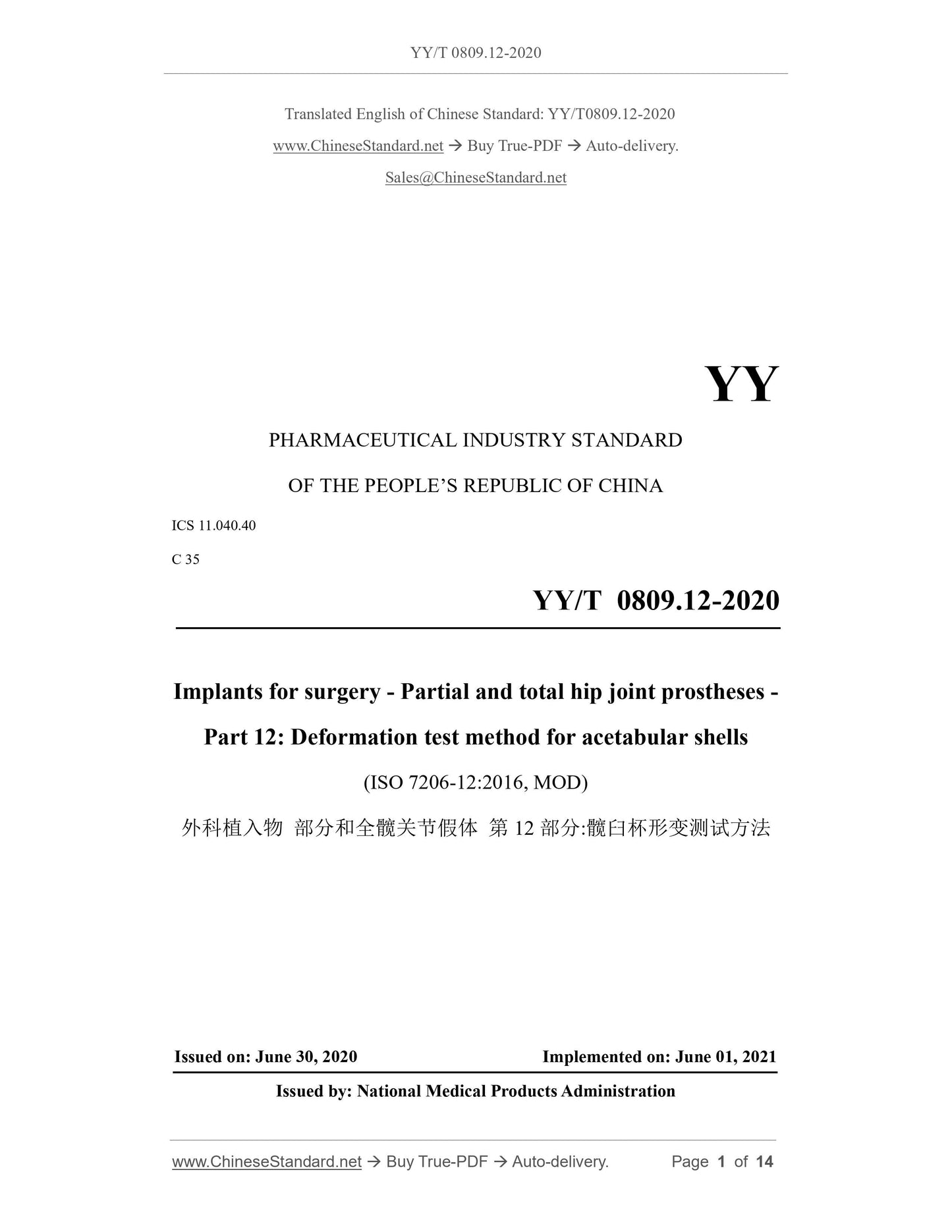
YY/T 0809.12-2020: Implants for surgery -- Partial and total hip joint prostheses -- Part 12: Deformation test method for acetabular shells
YY/T 0809.12-2020
YY
PHARMACEUTICAL INDUSTRY STANDARD
OF THE PEOPLE’S REPUBLIC OF CHINA
ICS 11.040.40
C 35
Implants for surgery - Partial and total hip joint prostheses -
Part 12: Deformation test method for acetabular shells
(ISO 7206-12:2016, MOD)
ISSUED ON: JUNE 30, 2020
IMPLEMENTED ON: JUNE 01, 2021
Issued by: National Medical Products Administration
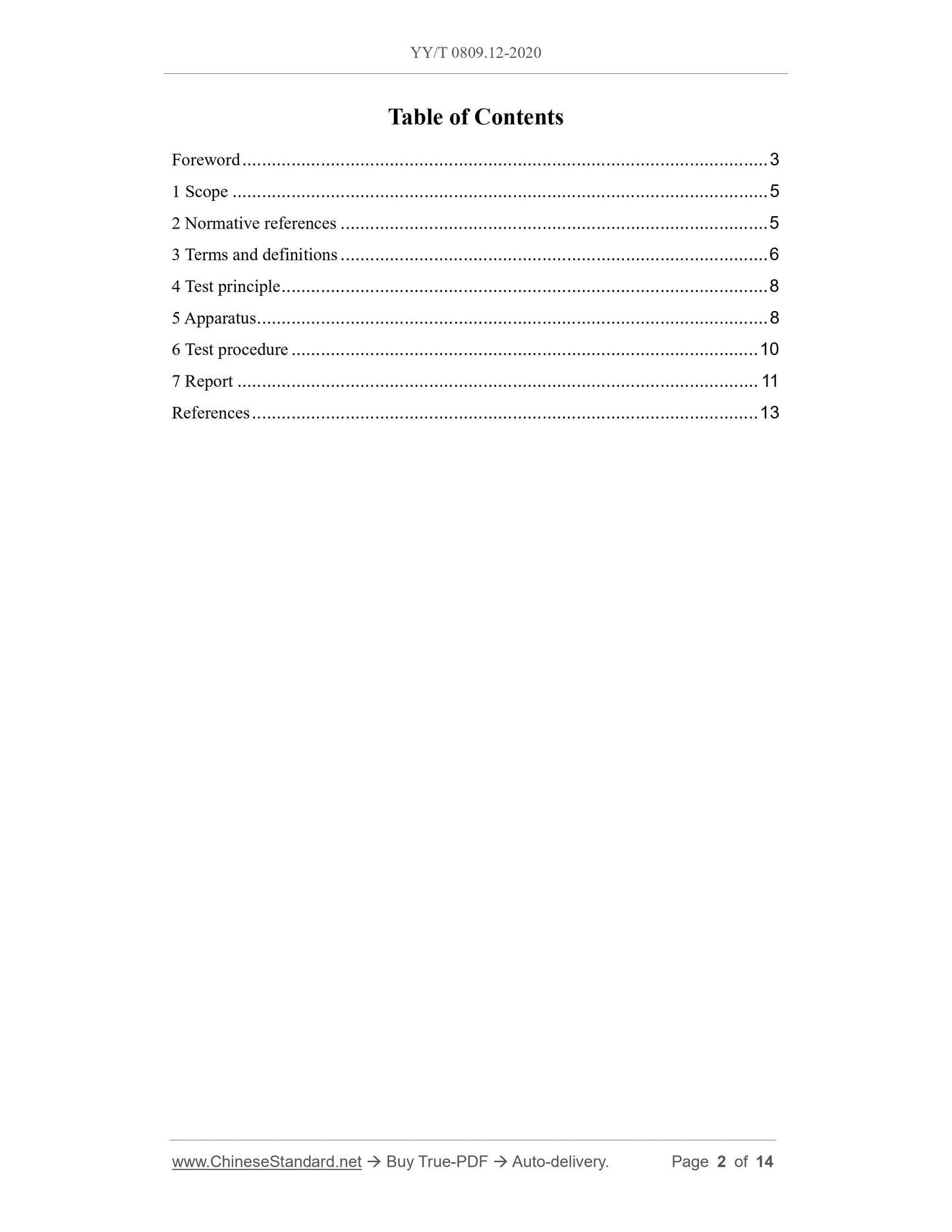
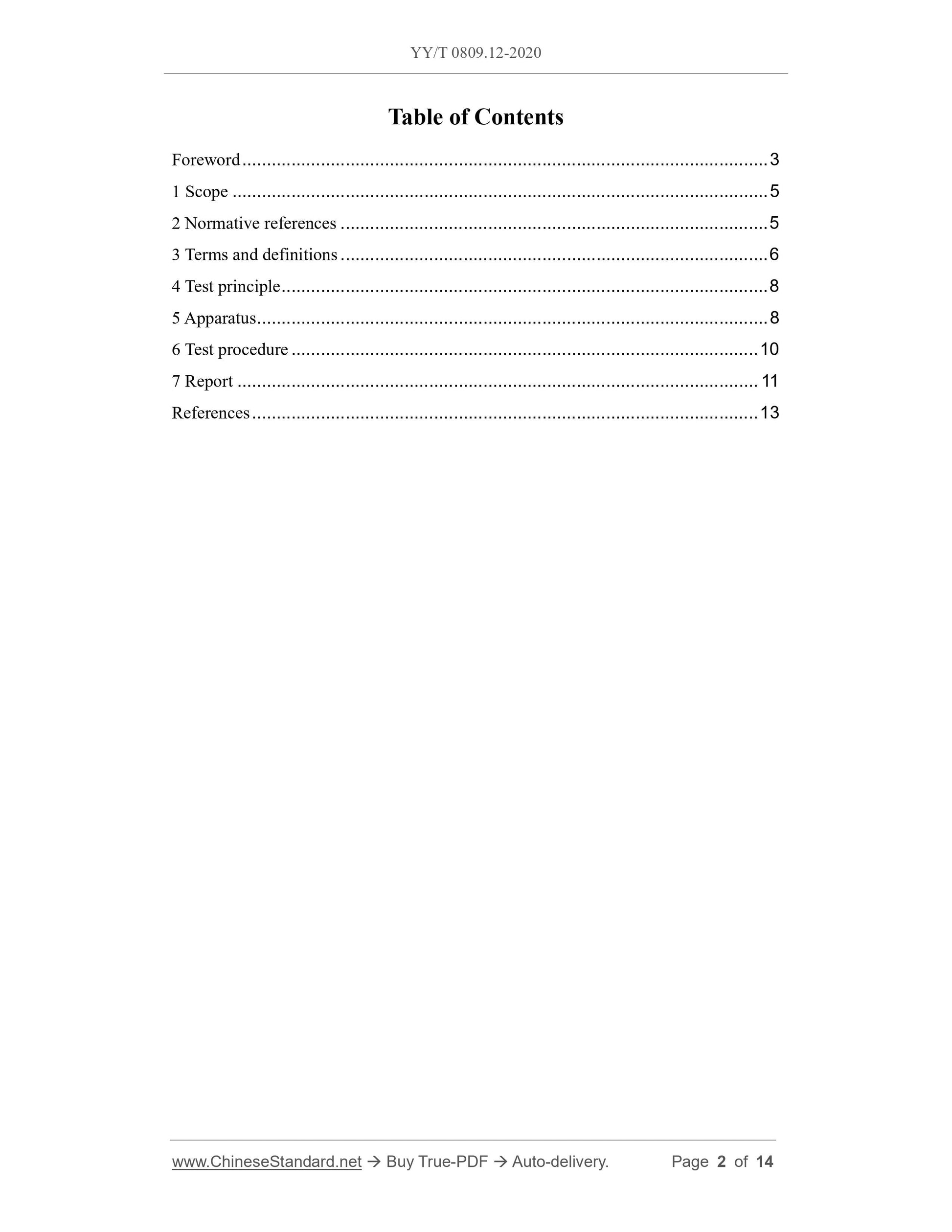
Table of Contents
Foreword ... 3
1 Scope ... 5
2 Normative references ... 5
3 Terms and definitions ... 6
4 Test principle ... 8
5 Apparatus ... 8
6 Test procedure ... 10
7 Report ... 11
References ... 13
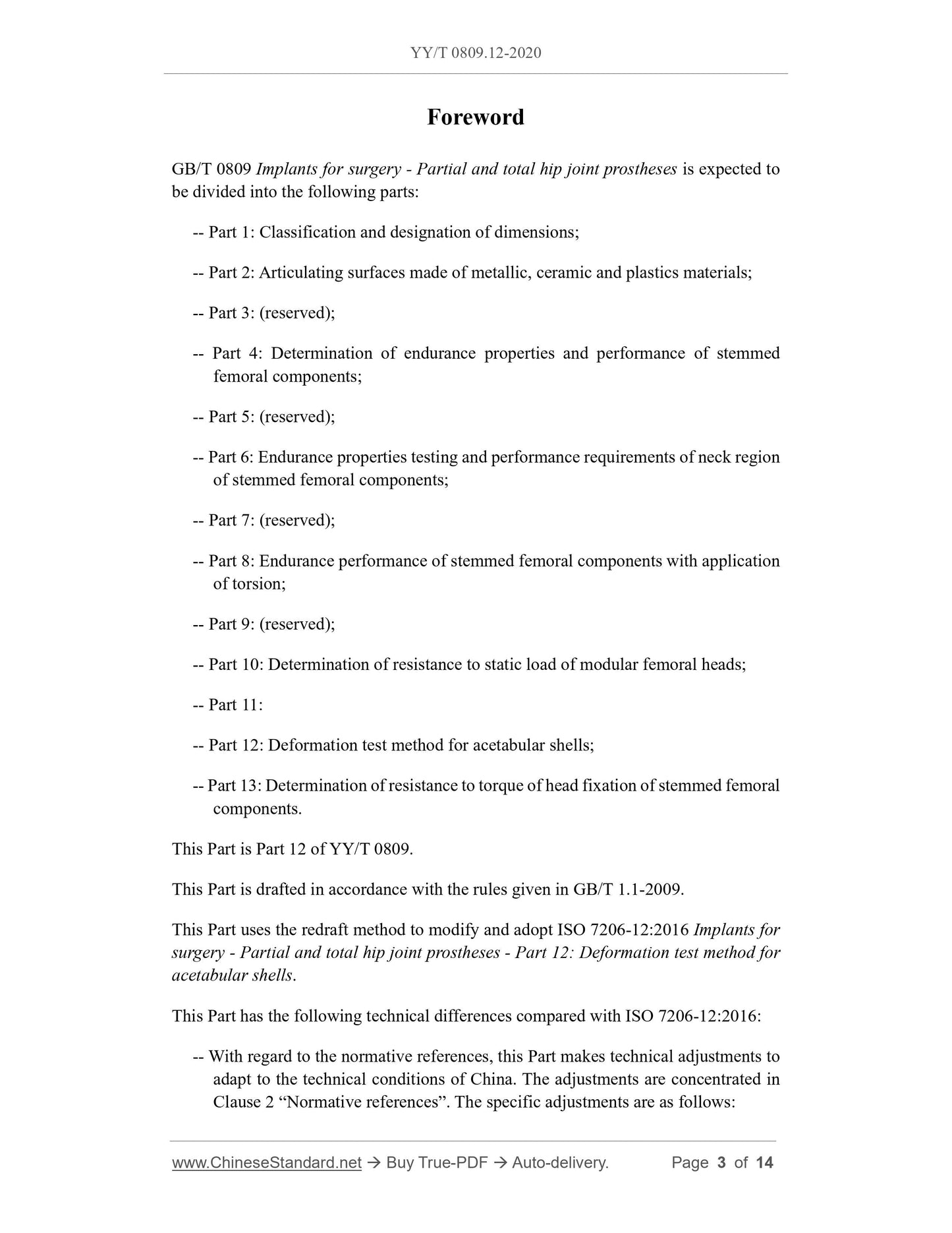
Foreword
GB/T 0809 Implants for surgery - Partial and total hip joint prostheses is expected to
be divided into the following parts:
-- Part 1: Classification and designation of dimensions;
-- Part 2: Articulating surfaces made of metallic, ceramic and plastics materials;
-- Part 3: (reserved);
-- Part 4: Determination of endurance properties and performance of stemmed
femoral components;
-- Part 5: (reserved);
-- Part 6: Endurance properties testing and performance requirements of neck region
of stemmed femoral components;
-- Part 7: (reserved);
-- Part 8: Endurance performance of stemmed femoral components with application
of torsion;
-- Part 9: (reserved);
-- Part 10: Determination of resistance to static load of modular femoral heads;
-- Part 11:
-- Part 12: Deformation test method for acetabular shells;
-- Part 13: Determination of resistance to torque of head fixation of stemmed femoral
components.
This Part is Part 12 of YY/T 0809.
This Part is drafted in accordance with the rules given in GB/T 1.1-2009.
This Part uses the redraft method to modify and adopt ISO 7206-12:2016 Implants for
surgery - Partial and total hip joint prostheses - Part 12: Deformation test method for
acetabular shells.
This Part has the following technical differences compared with ISO 7206-12:2016:
-- With regard to the normative references, this Part makes technical adjustments to
adapt to the technical conditions of China. The adjustments are concentrated in
Clause 2 “Normative references”. The specific adjustments are as follows:
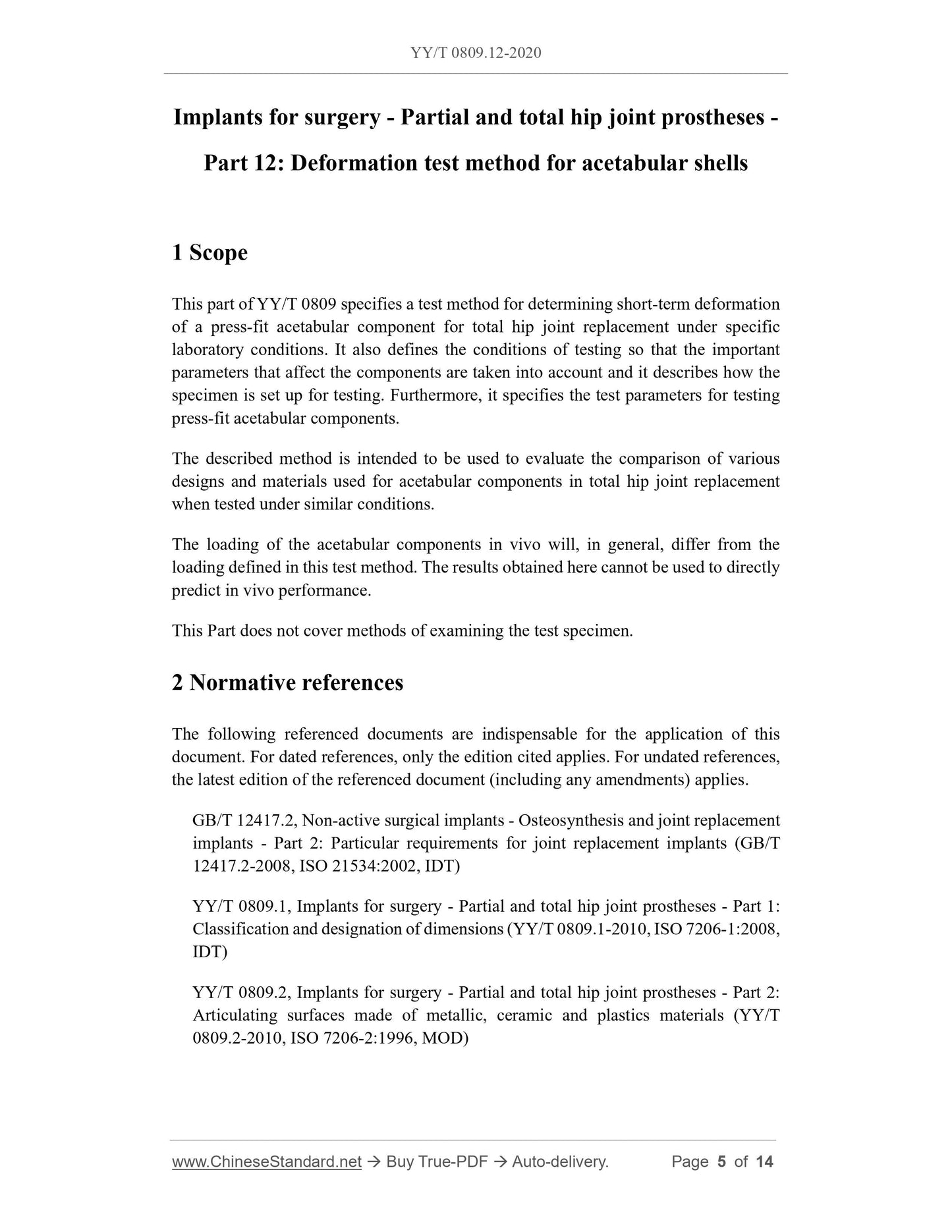
Implants for surgery - Partial and total hip joint prostheses -
Part 12: Deformation test method for acetabular shells
1 Scope
This part of YY/T 0809 specifies a test method for determining short-term deformation
of a press-fit acetabular component for total hip joint replacement under specific
laboratory conditions. It also defines the conditions of testing so that the important
parameters that affect the components are taken into account and it describes how the
specimen is set up for testing. Furthermore, it specifies the test parameters for testing
press-fit acetabular components.
The described method is intended to be used to evaluate the comparison of various
designs and materials used for acetabular components in total hip joint replacement
when tested under similar conditions.
The loading of the acetabular components in vivo will, in general, differ from the
loading defined in this test method. The results obtained here cannot be used to directly
predict in vivo performance.
This Part does not cover methods of examining the test specimen.
2 Normative references
The following referenced documents are indispensable for the application of this
document. For dated references, only the edition cited applies. For undated references,
the latest edition of the referenced document (including any amendments) applies.
GB/T 12417.2, Non-active surgical implants - Osteosynthesis and joint replacement
implants - Part 2: Particular requirements for joint replacement implants (GB/T
12417.2-2008, ISO 21534:2002, IDT)
YY/T 0809.1, Implants for surgery - Partial and total hip joint prostheses - Part 1:
Classification and designation of dimensions (YY/T 0809.1-2010, ISO 7206-1:2008,
IDT)
YY/T 0809.2, Implants for surgery - Partial and total hip joint prostheses - Part 2:
Articulating surfaces made of metallic, ceramic and plastics materials (YY/T
0809.2-2010, ISO 7206-2:1996, MOD)
clamping jaws shall be used which are designed in a way that the specimen can be fixed
and loaded.
The width of the clamping surface shall be at least 20 % of the outer diameter of the
test specimen at the frontal face reference plane allowing the manual centering of the
test specimen contact points on the clamping surfaces prior testing. Additional centering
features or tools are not necessary. If centering features or tools are provided, ensure
that the two-point loading and the deformation of the test specimen are not constrained.
The load cell shall be capable of measuring an axial compressive force with an
uncertainty of 1%.
5.2 Test specimen selection
The test specimen of that size of the acetabular component, which has been identified
to be the worst-case size, shall be randomly selected being representative for
manufacturing and shall have the same geometry and be made to the same material
specification through the same process as the final product.
Note: In case of modular acetabular components, the worst-case size for the first step
of testing (metal backing deformation) may be different from the worst-case size
of the second step of testing (articulating surface deformation of the acetabular
component).
If there are different articulating surface materials offered for the modular acetabular
components, then all insert articulating surface material and sizes shall be evaluated
regarding identification of worst-case material and sizes. Design features, such as
asymmetrically located screw holes, shall also be considered.
6 Test procedure
a) Prior to loading, measure the inner diameter, D0 [mm], of the specimen for each
of the planned loading directions by using a capable measurement device. The
diameter shall be measured in the measurement plane inside the spherical socket.
An uncertainty of the measurement of < 5 μm is required.
The diameter can additionally be measured at further positions in the same
measurement plane, e.g., perpendicular to the loading direction, for acquisition of
additional data on the general deformation behavior of the test specimen.
b) Position the specimen in the testing set-up and apply and maintain an axial force
of (1.00 ± 0.01) kN by steady turning the load adjustment screw. Avoid jerky
loading. The contact points of the specimen with the loading surfaces of the load
frame shall be located within the loading plane.
Share
