1
/
of
9
PayPal, credit cards. Download editable-PDF & invoice in 1 second!
YY/T 0888-2013 English PDF (YY/T0888-2013)
YY/T 0888-2013 English PDF (YY/T0888-2013)
Regular price
$110.00 USD
Regular price
Sale price
$110.00 USD
Unit price
/
per
Shipping calculated at checkout.
Couldn't load pickup availability
Delivery: 3 seconds. Download true-PDF + Invoice.
Get Quotation: Click YY/T 0888-2013 (Self-service in 1-minute)
Historical versions (Master-website): YY/T 0888-2013
Preview True-PDF (Reload/Scroll-down if blank)
YY/T 0888-2013: Imaging dose of X-ray image-guided devices used in radiotherapy equipment
YY/T 0888-2013
Imaging dose of X-ray image-guided devices used in radiotherapy equipment
ICS 11.040.60
C43
People's Republic of China pharmaceutical industry standards
Radiotherapy equipment X-ray image guidance device
Imaging dose
Issued on. 2013-10-21
2014-10-01 implementation
China Food and Drug Administration released
Foreword
This standard was drafted in accordance with GB/T 1.1-2009 given rules.
Please note that some of the content of this document may involve patents. Release mechanism of the present document does not assume responsibility for the identification of these patents.
This standard was proposed by the China Food and Drug Administration.
This standard by the National Standardization Technical Committee appliances medical radiotherapy, nuclear medicine science equipment at the Technical Committee and the radiation dose
(SAC/TC10/SC3) centralized.
This standard was drafted. Beijing Medical Device Control, Chinese Academy of Medical Sciences Cancer Hospital.
The main drafters. Zhang, Dai Jianrong, Xu Yan.
Radiotherapy equipment X-ray image guidance device
Imaging dose
1 Scope
This standard specifies the test methods for imaging dose radiotherapy equipment X-ray image guide means and random documentation requirements.
This standard applies to radiotherapy equipment X-ray image guidance device.
2 Normative references
The following documents for the application of this document is essential. For dated references, only the dated version suitable for use herein
Member. For undated references, the latest edition (including any amendments) applies to this document.
GB 9706.5-2008 Medical electrical equipment - Part 2. 1MeV to 50MeV energy safety of electron accelerators
Claim
GB/T 17857-1999 Medical imaging academic language (radiotherapy, nuclear medicine and radiation dosimetry equipment)
3 Terms and Definitions
GB/T 17857-1999 define the following terms and definitions apply to this document.
3.1
IGRT imageguidedradiotherapy; IGRT
According to various modes of image information obtained prior to treatment or fractionated fractionated therapy, treatment adjustment parameters (including patient positioning)
Radiation therapy.
3.2
Computed tomography image guide computedtomographicguidancedevice; CTGD
Radiation therapy equipment, the use of computed tomography technology for image-guided devices.
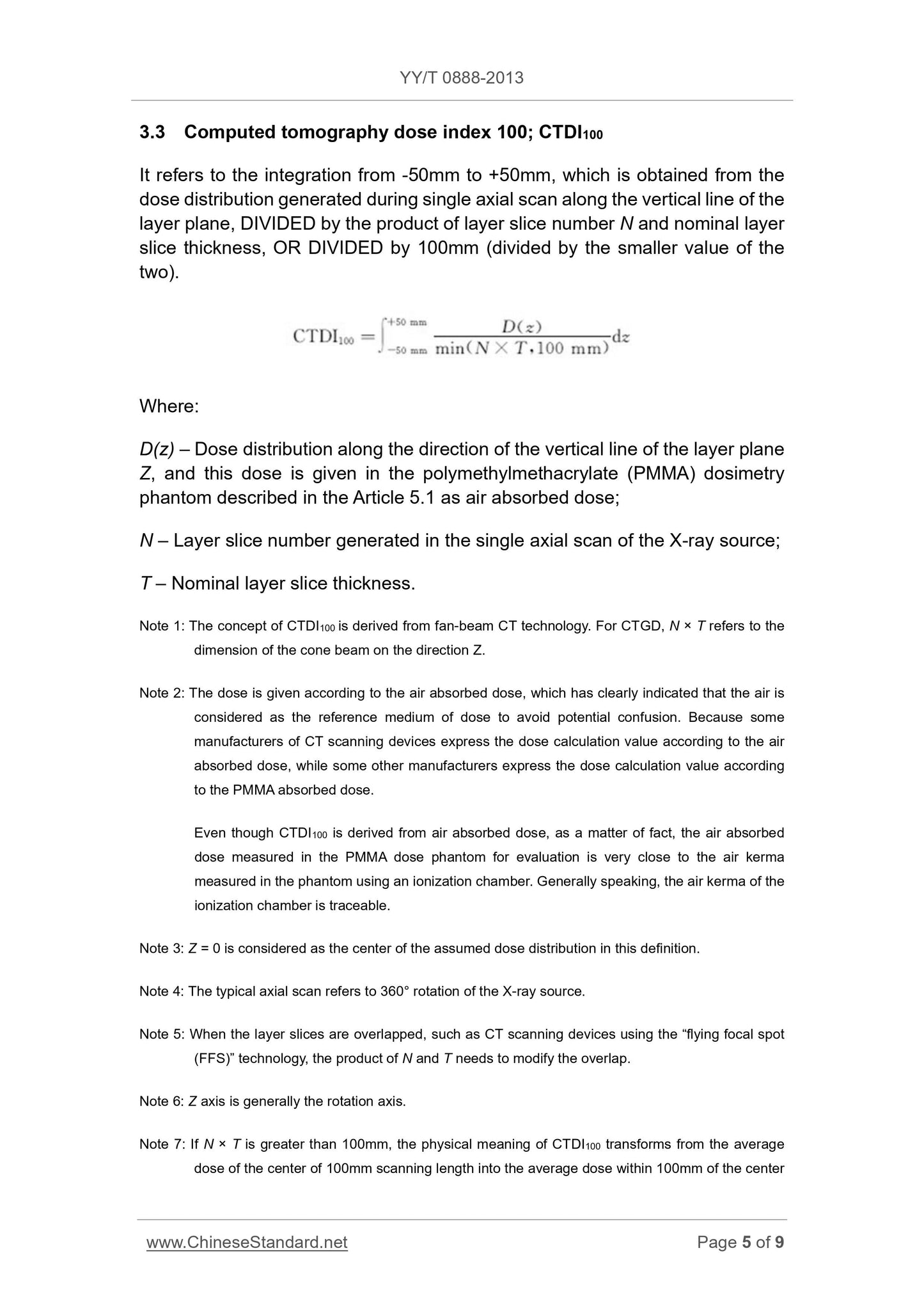
3.3
CT dose index 100computedtomographydoseindex100; CTDI100
Single doses axial scans generated along the layer plane perpendicular to the line dividing the distribution layer and the number of slices N nominal slice thickness layer
Product, or divided by 100mm (divided among the smaller of the two), from -50mm to 50mm points.
CTDI100 = ∫
50mm
-50mm
D (z)
min (N × T, 100mm) dz
Where.
D (z) --- along a line perpendicular to the plane layer dose distribution in the direction Z, the dosage is polymethyl methacrylate described in 5.1
Within (PMMA) dosimetry phantom, as air dose given;
N --- Number slice layer generated in the X-ray source a single axial scan;
T --- Nominal slice thickness layer.
Note 1. CTDI100 concept derived from the fan-beam CT technology. For CTGD speaking, N × T refers to the size of the Z-direction of the cone beam.
Note 2. Press the air dose dose given. Clearly indicate air as a reference medium dose to avoid potential confusion, because there are some CT sweep
Manufacturers described apparatus according to the air absorbed dose values represent the dose calculation, while others are based on the manufacturer and the absorbed dose of PMMA
To represent the dose calculated values.
Although CTDI100 from air absorbed dose, but in fact, air dose evaluation PMMA phantom dose measured from the ionization chamber and with a
Phantom measured air kerma fairly close. In general, the air ionization chamber kerma traceable.
Note 3. This definition assumes that the dose distribution to Z = 0 as the center.
Note 4. Typical axial scanning X-ray source rotate 360 °.
Note 5. When the layer overlapping slices, for example, a CT scanning device "flying focus" technology, N × T product requires overlapping amendment.
Note 6. generally Z-axis is a rotary axis.
Note 7. If N × T is greater than 100mm, the physical meaning CTDI100 would shift from the average dose scan length 100mm center is a single axial scan center
The average dose of 100mm inside.
Note 8. If the dose is less than the length of the phantom N × T 100mm, value CTDI100 will too small, because there is no full assessment of the scattered radiation.
4 General requirements
4.1 Description and display imaging dose
For X-ray imaging apparatus used in radiation therapy, in a predefined imaging conditions, imaging dose expected to be generated by the user
Described in this document, and should appear before imaging. The imaging unit dose should be used in imaging conditions specified.
Description 4.2 ACCOMPANYING DOCUMENTS imaging dose measurement methods
Imaging dose measurement method shall be specified in the manufacturer random file, these methods should refer to the corresponding standard imaging mode.
Compliance is verified by inspection of random files and check the manufacturer's test results.
5 kV level X-ray imaging dose CTGD description
5.1 kV level X-ray imaging dose phantom CTGD
IGRT equipment used kilovolt X-ray source CTGD means phantom imaging dose measurements should meet the following requirements.
By phantom dose density (1.19 ± 0.01) g/cm3 of the polymethacrylate (PMMA) cylinder made of the composition, for the first
Diameter part of 160mm, for the diameter of the body portion is 320mm, its length should be at least beyond the X-ray beam limiter opening portal length
10%, and greater than the length of the phantom for measuring radiation detector sensitive area.
Phantom should be capable of adapting the radiation detector apertures should be parallel to the central axis of the phantom, and the center should be located in the center of the phantom
And in 90 ° intervals at 10mm below the surface of the phantom. For the hole measured not in use, you should use the same phantom material insert
Is fully inserted into the hole.
5.2 ACCOMPANYING DOCUMENTS CTDI100 dosage instructions
5.2.1 IGRT equipment kilovolt X-ray CTGD means using a predetermined phantom obtain 5.1 The following dosage information. For any
CTGD scanning means shall be provided for each application (such as the head, body, etc.) were dose information in a random file. This should be measured
The dose phantom placed on the couch, in the absence of any additional attenuation material situation. Phantom dose should be at the center of the scanning area,
And scanning means located CTGD rotation shaft.
Information 5.2.2 For each application, accompanying documents should be given
5.2.2.1 CTGD operating conditions (should be recommended by the manufacturer of the typical value), using the prescribed dose of 5.1 phantom Under this condition, in
CTDI100 measured value following locations.
a) The radiation detector insertion hole measuring phantom center to find out the location of the maximum value of the axial CTDI100 move the couch to give the phantom
CTDI100 rotational axis (center).
b) along a line parallel to the axis of rotation, the radiation detector is inserted to the inside of a 10mm hole distance measuring phantom surface.
c) from b) the location, around the phantom axis of rotation 90 °, 180 ° and 270 ° position. The maximum value of placed CTDI100
Position should be based on the scanning machine housing or other easily identifiable member CTGD scanning device, as given by b) under the
Positioned to be placed in this direction phantom.
d) CTDI100 (surrounding) four CTDI100 flat by 5.2.2.1b) and 5.2.2.1c) specified in the phantom dose measurements periphery
Mean.
5.2.2.2 For each alternative CTGD operating conditions change CTDI100 (center) value will cause the dose phantom center position
CTDI100 change.
The CTDI100 (center) will be applied dose phantom center position CTDI100 5.2.2.1 according to a value of normalized be represented.
5.2.2.1 belongs CTDI100 (center) is 1. When changing a single CTGD operating conditions, all other independent CTGD run
Conditions should be maintained at the typical values 5.2.2.1. These data should be run every CTGD conditions specified by the manufacturer of the
Accordingly the range. When you select a CTGD operating conditions more than three, it shall be given at least the minimum CTGD under operating conditions,
Normalized CTDI100 value when a maximum and intermediate.
5.2.2.3 under each alternative CTGD operating conditions, CTDI100 (peripheral) average.
The CTDI100 (peripheral) applications will CTDI100 (vicinity) dose phantom center position 5.2.2.1 according to a value normalized to the table
Shows, 5.2.2.1 belongs CTDI100 (periphery) is 1. When changing a single CTGD operating conditions, all other independent CT run
Conditions should be maintained at the typical values 5.2.2.1. These data should be run every CTGD conditions specified by the manufacturer of the
Accordingly the range. When you select a CTGD operating conditions more than three, it shall be given at least the minimum CTGD under operating conditions,
Normalized maximum and an intermediate value of CTDI100 (peripheral) value.
5.2.2.4 The manufacturer should state the maximum deviation of the measured values 5.2.2.1 ~ 5.2.2.3. Deviation of all measured values shall not exceed the maximum
deviation.
Compliance is verified by inspection of random files and check the manufacturer's test results.
6 MeV X-ray imaging dose CTGD description
For 6.1 MeV energy X-ray source CTGD, one of the following methods should pass on the reference point within the 3D volume imaging obtained
Imaging dose.
--- Radiation detectors by GB 9706.5-2008 prescribed in 29.1.1.1, is displayed as dose monitoring count (MU), can pass
Through the dose monitor count (MU) is calculated within the imaging volume of absorbed dose reference point.
--- By radiation treatment planning system (RTPS), contains 3D imaging dose absorbed dose plan.
--- By other means, shall be described in the instructions for use.
6.2 accompanying documents should provide a suitable dose of phantom. Its length should be at least exceed the maximum edge equipment available slice thickness layer on both sides
1cm. Phantom length should exceed the length of the radiation detectors used in the measurement of the sensitive area. Phantom should be sufficient adaptation radiation probe
The instrumental apertures should be parallel to the axis of symmetry of the mold body, and its depth is sufficient to accommodate the radiation detector, such that the center position of the measurement area
In parallel to the central plane of the end surface of the phantom. Phantom circular end surface along the radial direction should be set a series of holes to place the radiation detector test
Amount from the central axis of the phantom on the radiation dose at different distances. For the hole measured not in use, you should use the same phantom material insert
Is fully inserted into the hole.
6.3 Random file should contain.
--- Position with respect to the phantom center and other centers, the location can be phantom complete digital image reconstruction.
--- Covering the entire volume of the ionization chamber reference phantom minimum length, outside the sensitive volume of the phantom material before and after the required minimum.
--- Accompanying documents should indicate collimated imaging beam shape.
Compliance is verified by inspection of random files and check the manufacturer's test results.
Get Quotation: Click YY/T 0888-2013 (Self-service in 1-minute)
Historical versions (Master-website): YY/T 0888-2013
Preview True-PDF (Reload/Scroll-down if blank)
YY/T 0888-2013: Imaging dose of X-ray image-guided devices used in radiotherapy equipment
YY/T 0888-2013
Imaging dose of X-ray image-guided devices used in radiotherapy equipment
ICS 11.040.60
C43
People's Republic of China pharmaceutical industry standards
Radiotherapy equipment X-ray image guidance device
Imaging dose
Issued on. 2013-10-21
2014-10-01 implementation
China Food and Drug Administration released
Foreword
This standard was drafted in accordance with GB/T 1.1-2009 given rules.
Please note that some of the content of this document may involve patents. Release mechanism of the present document does not assume responsibility for the identification of these patents.
This standard was proposed by the China Food and Drug Administration.
This standard by the National Standardization Technical Committee appliances medical radiotherapy, nuclear medicine science equipment at the Technical Committee and the radiation dose
(SAC/TC10/SC3) centralized.
This standard was drafted. Beijing Medical Device Control, Chinese Academy of Medical Sciences Cancer Hospital.
The main drafters. Zhang, Dai Jianrong, Xu Yan.
Radiotherapy equipment X-ray image guidance device
Imaging dose
1 Scope
This standard specifies the test methods for imaging dose radiotherapy equipment X-ray image guide means and random documentation requirements.
This standard applies to radiotherapy equipment X-ray image guidance device.
2 Normative references
The following documents for the application of this document is essential. For dated references, only the dated version suitable for use herein
Member. For undated references, the latest edition (including any amendments) applies to this document.
GB 9706.5-2008 Medical electrical equipment - Part 2. 1MeV to 50MeV energy safety of electron accelerators
Claim
GB/T 17857-1999 Medical imaging academic language (radiotherapy, nuclear medicine and radiation dosimetry equipment)
3 Terms and Definitions
GB/T 17857-1999 define the following terms and definitions apply to this document.
3.1
IGRT imageguidedradiotherapy; IGRT
According to various modes of image information obtained prior to treatment or fractionated fractionated therapy, treatment adjustment parameters (including patient positioning)
Radiation therapy.
3.2
Computed tomography image guide computedtomographicguidancedevice; CTGD
Radiation therapy equipment, the use of computed tomography technology for image-guided devices.
3.3
CT dose index 100computedtomographydoseindex100; CTDI100
Single doses axial scans generated along the layer plane perpendicular to the line dividing the distribution layer and the number of slices N nominal slice thickness layer
Product, or divided by 100mm (divided among the smaller of the two), from -50mm to 50mm points.
CTDI100 = ∫
50mm
-50mm
D (z)
min (N × T, 100mm) dz
Where.
D (z) --- along a line perpendicular to the plane layer dose distribution in the direction Z, the dosage is polymethyl methacrylate described in 5.1
Within (PMMA) dosimetry phantom, as air dose given;
N --- Number slice layer generated in the X-ray source a single axial scan;
T --- Nominal slice thickness layer.
Note 1. CTDI100 concept derived from the fan-beam CT technology. For CTGD speaking, N × T refers to the size of the Z-direction of the cone beam.
Note 2. Press the air dose dose given. Clearly indicate air as a reference medium dose to avoid potential confusion, because there are some CT sweep
Manufacturers described apparatus according to the air absorbed dose values represent the dose calculation, while others are based on the manufacturer and the absorbed dose of PMMA
To represent the dose calculated values.
Although CTDI100 from air absorbed dose, but in fact, air dose evaluation PMMA phantom dose measured from the ionization chamber and with a
Phantom measured air kerma fairly close. In general, the air ionization chamber kerma traceable.
Note 3. This definition assumes that the dose distribution to Z = 0 as the center.
Note 4. Typical axial scanning X-ray source rotate 360 °.
Note 5. When the layer overlapping slices, for example, a CT scanning device "flying focus" technology, N × T product requires overlapping amendment.
Note 6. generally Z-axis is a rotary axis.
Note 7. If N × T is greater than 100mm, the physical meaning CTDI100 would shift from the average dose scan length 100mm center is a single axial scan center
The average dose of 100mm inside.
Note 8. If the dose is less than the length of the phantom N × T 100mm, value CTDI100 will too small, because there is no full assessment of the scattered radiation.
4 General requirements
4.1 Description and display imaging dose
For X-ray imaging apparatus used in radiation therapy, in a predefined imaging conditions, imaging dose expected to be generated by the user
Described in this document, and should appear before imaging. The imaging unit dose should be used in imaging conditions specified.
Description 4.2 ACCOMPANYING DOCUMENTS imaging dose measurement methods
Imaging dose measurement method shall be specified in the manufacturer random file, these methods should refer to the corresponding standard imaging mode.
Compliance is verified by inspection of random files and check the manufacturer's test results.
5 kV level X-ray imaging dose CTGD description
5.1 kV level X-ray imaging dose phantom CTGD
IGRT equipment used kilovolt X-ray source CTGD means phantom imaging dose measurements should meet the following requirements.
By phantom dose density (1.19 ± 0.01) g/cm3 of the polymethacrylate (PMMA) cylinder made of the composition, for the first
Diameter part of 160mm, for the diameter of the body portion is 320mm, its length should be at least beyond the X-ray beam limiter opening portal length
10%, and greater than the length of the phantom for measuring radiation detector sensitive area.
Phantom should be capable of adapting the radiation detector apertures should be parallel to the central axis of the phantom, and the center should be located in the center of the phantom
And in 90 ° intervals at 10mm below the surface of the phantom. For the hole measured not in use, you should use the same phantom material insert
Is fully inserted into the hole.
5.2 ACCOMPANYING DOCUMENTS CTDI100 dosage instructions
5.2.1 IGRT equipment kilovolt X-ray CTGD means using a predetermined phantom obtain 5.1 The following dosage information. For any
CTGD scanning means shall be provided for each application (such as the head, body, etc.) were dose information in a random file. This should be measured
The dose phantom placed on the couch, in the absence of any additional attenuation material situation. Phantom dose should be at the center of the scanning area,
And scanning means located CTGD rotation shaft.
Information 5.2.2 For each application, accompanying documents should be given
5.2.2.1 CTGD operating conditions (should be recommended by the manufacturer of the typical value), using the prescribed dose of 5.1 phantom Under this condition, in
CTDI100 measured value following locations.
a) The radiation detector insertion hole measuring phantom center to find out the location of the maximum value of the axial CTDI100 move the couch to give the phantom
CTDI100 rotational axis (center).
b) along a line parallel to the axis of rotation, the radiation detector is inserted to the inside of a 10mm hole distance measuring phantom surface.
c) from b) the location, around the phantom axis of rotation 90 °, 180 ° and 270 ° position. The maximum value of placed CTDI100
Position should be based on the scanning machine housing or other easily identifiable member CTGD scanning device, as given by b) under the
Positioned to be placed in this direction phantom.
d) CTDI100 (surrounding) four CTDI100 flat by 5.2.2.1b) and 5.2.2.1c) specified in the phantom dose measurements periphery
Mean.
5.2.2.2 For each alternative CTGD operating conditions change CTDI100 (center) value will cause the dose phantom center position
CTDI100 change.
The CTDI100 (center) will be applied dose phantom center position CTDI100 5.2.2.1 according to a value of normalized be represented.
5.2.2.1 belongs CTDI100 (center) is 1. When changing a single CTGD operating conditions, all other independent CTGD run
Conditions should be maintained at the typical values 5.2.2.1. These data should be run every CTGD conditions specified by the manufacturer of the
Accordingly the range. When you select a CTGD operating conditions more than three, it shall be given at least the minimum CTGD under operating conditions,
Normalized CTDI100 value when a maximum and intermediate.
5.2.2.3 under each alternative CTGD operating conditions, CTDI100 (peripheral) average.
The CTDI100 (peripheral) applications will CTDI100 (vicinity) dose phantom center position 5.2.2.1 according to a value normalized to the table
Shows, 5.2.2.1 belongs CTDI100 (periphery) is 1. When changing a single CTGD operating conditions, all other independent CT run
Conditions should be maintained at the typical values 5.2.2.1. These data should be run every CTGD conditions specified by the manufacturer of the
Accordingly the range. When you select a CTGD operating conditions more than three, it shall be given at least the minimum CTGD under operating conditions,
Normalized maximum and an intermediate value of CTDI100 (peripheral) value.
5.2.2.4 The manufacturer should state the maximum deviation of the measured values 5.2.2.1 ~ 5.2.2.3. Deviation of all measured values shall not exceed the maximum
deviation.
Compliance is verified by inspection of random files and check the manufacturer's test results.
6 MeV X-ray imaging dose CTGD description
For 6.1 MeV energy X-ray source CTGD, one of the following methods should pass on the reference point within the 3D volume imaging obtained
Imaging dose.
--- Radiation detectors by GB 9706.5-2008 prescribed in 29.1.1.1, is displayed as dose monitoring count (MU), can pass
Through the dose monitor count (MU) is calculated within the imaging volume of absorbed dose reference point.
--- By radiation treatment planning system (RTPS), contains 3D imaging dose absorbed dose plan.
--- By other means, shall be described in the instructions for use.
6.2 accompanying documents should provide a suitable dose of phantom. Its length should be at least exceed the maximum edge equipment available slice thickness layer on both sides
1cm. Phantom length should exceed the length of the radiation detectors used in the measurement of the sensitive area. Phantom should be sufficient adaptation radiation probe
The instrumental apertures should be parallel to the axis of symmetry of the mold body, and its depth is sufficient to accommodate the radiation detector, such that the center position of the measurement area
In parallel to the central plane of the end surface of the phantom. Phantom circular end surface along the radial direction should be set a series of holes to place the radiation detector test
Amount from the central axis of the phantom on the radiation dose at different distances. For the hole measured not in use, you should use the same phantom material insert
Is fully inserted into the hole.
6.3 Random file should contain.
--- Position with respect to the phantom center and other centers, the location can be phantom complete digital image reconstruction.
--- Covering the entire volume of the ionization chamber reference phantom minimum length, outside the sensitive volume of the phantom material before and after the required minimum.
--- Accompanying documents should indicate collimated imaging beam shape.
Compliance is verified by inspection of random files and check the manufacturer's test results.
Share