
1
/
of
12
PayPal, credit cards. Download editable-PDF & invoice in 1 second!
YY/T 0987.2-2016 English PDF (YY/T0987.2-2016)
YY/T 0987.2-2016 English PDF (YY/T0987.2-2016)
Regular price
$140.00 USD
Regular price
Sale price
$140.00 USD
Unit price
/
per
Shipping calculated at checkout.
Couldn't load pickup availability
Delivery: 3 seconds. Download true-PDF + Invoice.
Get Quotation: Click YY/T 0987.2-2016 (Self-service in 1-minute)
Historical versions (Master-website): YY/T 0987.2-2016
Preview True-PDF (Reload/Scroll-down if blank)
YY/T 0987.2-2016: Implants for Surgery - Magnetic Resonance Compatibility - Part 2: Magnetically Induced Displacement Force Test Method
YY/T 0987.2-2016
Implants for surgery--Magnetic resonance compatibility--Part 2. Magnetically induced displacement force test method
ICS 11.040.40
C35
People's Republic of China Pharmaceutical Industry Standard
Surgical implant magnetic resonance compatibility
Part 2. Magnetic displacement force test method
Part 2.Magneticalyinduceddisplacementforcetestmethod
Published on.2016-03-23
2017-01-01 implementation
State Food and Drug Administration issued
Content
Foreword III
1 range 1
2 Normative references 1
3 Terms and Definitions 1
4 Test method overview 3
5 Significance and application 3
6 instruments and equipment 3
7 test sample 3
8 Step 3
9 Data Processing 4
10 Report 4
Appendix A (informative) Basic Principles 6
Reference 8
Foreword
YY/T 0987 "Surgical Implant Magnetic Resonance Compatibility" is divided into the following sections.
--- Part 1. Security mark;
--- Part 2. Magnetic displacement force test method;
--- Part 3. Image artifact evaluation method;
--- Part 4. Radiofrequency heating test methods;
--- Part 5. Magnetic torque test method.
This part is the second part of YY/T 0987.
This part is drafted in accordance with the rules given in GB/T 1.1-2009.
This section uses the redrafting method with reference to ASTM F2052-2006 "Standard test of magnetic displacement force of medical equipment in magnetic resonance environment"
Methodology.
The technical differences between this part and ASTMF2052-2006 are as follows.
---About the normative reference documents, this part has made technical adjustments to adapt to China's technical conditions, adjustments
The situation is reflected in Chapter 2, “Regulatory Citations”, and the specific adjustments are as follows.
● Replace ASTMF2503-08 with YY/T 0987.1;
● Replace ASTMF2119-07 with YY/T 0987.3;
● Replace ASTMF2182-11a with YY/T 0987.4;
● Replace ASTMF2213-06 with YY/T 0987.5.
--- Remove Chapter 12 of ASTMF2052-2006.
Please note that some of the contents of this document may involve patents. The issuing organization of this document is not responsible for identifying these patents.
This part is proposed by the State Food and Drug Administration.
This part is under the jurisdiction of the National Technical Committee for Standardization of Surgical Implants and Orthopedic Devices (SAC/TC110).
This section drafted by. State Food and Drug Administration Tianjin Medical Device Quality Supervision and Inspection Center, minimally invasive medical equipment (Shanghai)
Limited.
The main drafters of this section. Li Jia, Yan Hui, Qi Baofen, Sun Bing, Shi Haifeng.
Surgical implant magnetic resonance compatibility
Part 2. Magnetic displacement force test method
1 Scope
This part of YY/T 0987 includes the test method and magnetically induced magnetic displacement force of medical devices due to static gradient magnetic fields.
Comparison of shifting force and instrument weight.
This section does not address other possible safety issues including, but not limited to, magneto-induced torque, RF heating and heating, noise,
The interaction between instruments, the function of the instrument and the magnetic resonance system.
This section applies to instruments that can be suspended by a wire. Instruments that cannot be suspended with a wire are not suitable. The line used to suspend the instrument during the test
The weight should be less than 1% of the weight of the test instrument.
The tests in this section should be performed in a system where the direction of the magneto-displacement force is horizontal.
This section uses the values of the International System of Units as the standard. The values in parentheses are for reference only.
This section is not intended to address all of the security issues involved, even those related to their use. Indeed
It is the responsibility of the users of this standard to establish appropriate safety and health practices and to clarify the applicability of regulatory restrictions prior to application.
2 Normative references
The following documents are indispensable for the application of this document. For dated references, only the dated version applies to this article.
Pieces. For undated references, the latest edition (including all amendments) applies to this document.
YY/T 0987.1 Surgical implants - Magnetic resonance - Part 1
YY/T 0987.3 Magnetic resonance compatibility of surgical implants - Part 3. Methods of image artifact evaluation
YY/T 0987.4 Magnetic resonance compatibility of surgical implants - Part 4. Radio-thermal test method
Surgical implants - Magnetic resonance compatibility - Part 5. Magnetic torque test method
3 Terms and definitions
The following terms and definitions apply to this document.
3.1
Magnetic material diamagneticmaterial
A material with a relative magnetic permeability of less than one.
3.2
Ferromagnetic material ferromagneticmaterial
The magnetic moments are ordered and arranged in parallel in a direction to produce a magnetized material.
3.3
Magnetic field strength magneticfieldstrength
The strength of the applied magnetic field, symbol H, in ampere per meter (A/m).
3.4
Magnetic induction
Flux density magneticfluxdensity
a magnetic field measured by the induced electromotive force generated in the point loop by the force or flux change at any point in the magnetic field
strength. The magnetic induction is often referred to as the magnetic field strength. B0 refers to the static magnetic field strength of the MR system, symbol B, in Tesla (T).
The scalar is represented by a normal font (such as B) and the vector is shown in bold (such as B).
3.5
Magnetic resonance diagnostic equipment magneticresonancediagnosticdevice
An imaging apparatus for conventional diagnosis, the image formed of which can reflect the spatial distribution of atoms and/or a magnetic resonance spectrum, wherein the magnetic resonance spectrum
It reflects the frequency and distribution of the atoms that produce magnetic resonance. Other physical parameters are also available from the image and/or the spectrum.
3.6
Magnetic resonance (MR) environment magneticresonance (MR) environment
The space within the 0.5mT (5G) line in the MR system, including the entire three-dimensional space around the MR scanner. When the 0.5mT line is included
When Faraday is inside the cage, the entire space should be considered a magnetic resonance (MR) environment.
3.7
Magnetic resonance equipment magneticresonanceequipment
MR equipment
Medical electrical equipment intended for in vivo magnetic resonance examination. Magnetic resonance equipment includes all hardware from the main power supply to the display monitor and
Software part. The magnetic resonance device is a programmable medical electrical system (PEMS).
3.8
Magnetic resonance system magneticresonancesystem
MR system MRsystem
A combination of magnetic resonance equipment, accessories (including display, control, and energy supply) and controlled access areas (if provided).
3.9
Magnetic resonance examination magneticresonanceexamination
MR examination MRexamination
The process of collecting patient data by magnetic resonance.
3.10
Magnetic resonance magnetic resonance
The resonance absorption of the electromagnetic field energy by a group of atomic particles located in a magnetic field.
3.11
Medical device medicaldevice
The intended use of the manufacturer is for human use, either alone or in combination, including the use of the required software.
Any instrument, equipment, appliance, material or other item for the purposes of.
--- Diagnosis, prevention, monitoring, treatment or relief of the disease;
--- Diagnosis, monitoring, treatment, mitigation or compensation for disability;
--- Research, replacement or regulation of anatomical or physiological processes.
Its main expected effects on the body surface and in the body are not obtained by pharmacological, immunological or metabolic means, but may have these
Means participate and play a certain auxiliary role.
3.12
Magnetic displacement force magneticalyinduceddisplacementforce
The force that a magnetic object is located in a spatial gradient magnetic field that causes the magnetic object to move in the gradient field.
3.13
Paramagnetic material paramagneticmaterial
A material with a relative magnetic permeability slightly larger than 1 is almost free of magnetic force.
3.14
Tesla tesla
The international unit of magnetic induction, equivalent to 104 Gauss (G).
4 Overview of test methods
The medical device is suspended by a wire in a position in the magnetic field that produces the greatest magnetic offset. Measure the offset angle of the line relative to the vertical, if
If the offset angle of the instrument is less than 45°, then the magnetic displacement force is less than the gravity (the weight of the instrument) that the instrument is subjected to.
5 Significance and application
This part of the test method is to determine whether the presence of a medical device during MR examination or in the MR environment will lead to patient injury.
One of the methods. Other safety issues that need to be addressed, including but not limited to magneto-induced torque (see YY/T 0987.5) and RF heating (see
YY/T 0987.4). The safety of the device in a magnetic resonance environment should be carried out using the terms and markings specified in YY/T 0987.1
mark.
If the offset angle of the instrument is less than 45°, the magnetically displaced force is less than the gravity (the weight of the instrument) that the instrument is subjected to. under these circumstances,
It can be considered that the risk of magnetically induced displacement is not higher than the risk of daily activities in the Earth's gravitational field.
An instrument with an offset angle of less than 45° at the maximum static magnetic field gradient of an MR system does not ensure that it is at a higher magnetic field strength or
The offset angle produced in systems with larger static magnetic field gradients is also less than 45°.
This test alone is not sufficient to demonstrate the safety of the device in a magnetic resonance environment.
6 instruments
The test device consists of a sturdy, non-magnetic stand that can be hung from the device under test without offset, with a minimum scale of 1°.
The protractor is firmly mounted on the bracket, the 0° scale of the protractor is in the vertical direction, and the instrument under test is suspended from the 0° scale of the protractor.
Connected online. In order to make the weight of the wire negligible compared to the device under test, the weight of the wire should not exceed 1% of the weight of the device. Line should be enough
The length allows the instrument to be suspended from the test device and naturally hangs down. The movement of the wire should not be restricted by the bracket or the protractor. The suspension wire can be connected to the device.
The right location.
7 test samples
Instruments evaluated in accordance with the test methods in this section shall be representative of finished products that have been subjected to final treatment (eg, sterilization).
Test equipment should not be altered in any way prior to testing.
8 steps
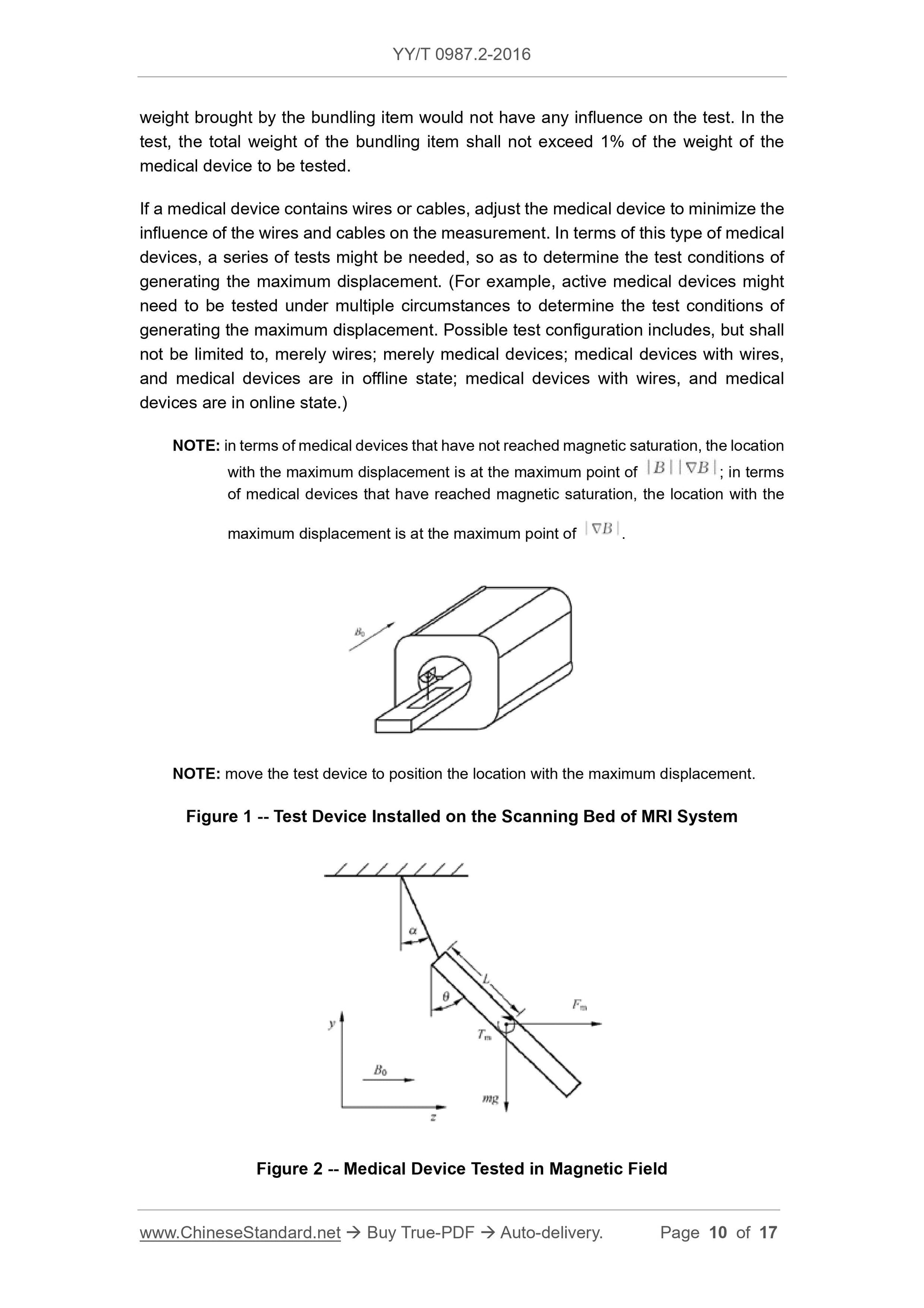
Any magnet capable of producing a large gradient horizontal magnetic field can be used in this test. Figure 1 shows the test installed on the scanning bed of the MRI system.
Inspection device. The test instrument is suspended by a wire, and the suspension line coincides with the 0° scale of the protractor. Adjust the position of the test device so that the center of mass of the instrument is offset
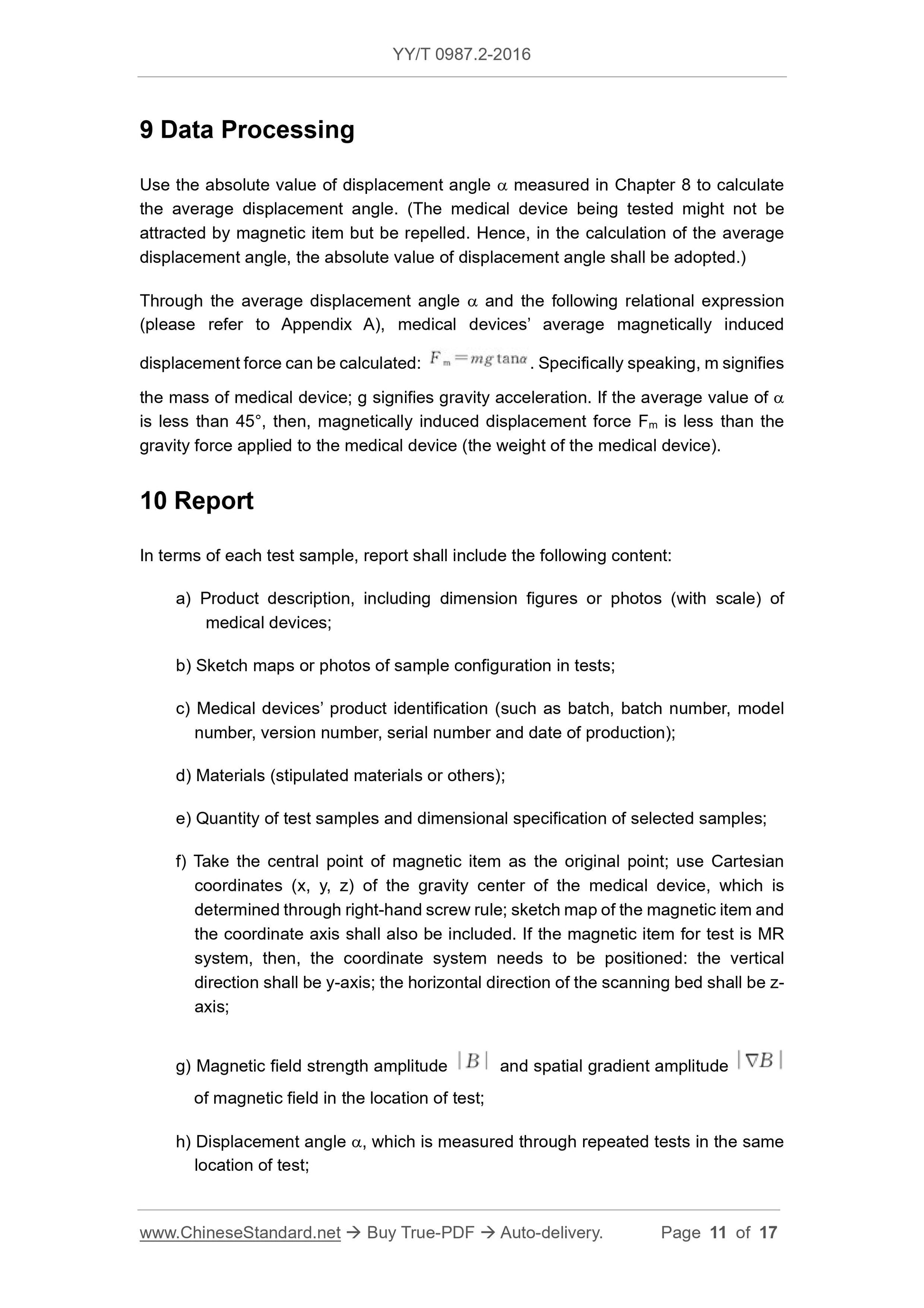
The maximum position (see note), marking this maximum offset position, all tests should be repeated at the same location. Grasp the instrument to keep the suspension line upright
Straight, then release the instrument and record the offset angle α of the instrument from the vertical position to the nearest 1° position (see Figure 2).
Repeat the above steps and test each test sample at least 3 times.
In order for the instrument to be located at the maximum offset angle position, the instrument should be bundled. If the test uses a bundled item (such as glue)
Belt), it should be proven that the extra weight it brings will not affect the test. The total weight of the items used to bind the device during the test shall not exceed the test.
1% of the weight of the device.
If the device contains wires or cables, adjust the instrument to minimize the impact of the wire or cable on the measurement. For such devices, it may be necessary to enter
A series of tests were performed to determine the test conditions that produced the greatest offset. (For example. for active devices, it may be necessary to test in a variety of situations
Determine the test conditions that produce the maximum offset. Possible test configurations include, but are not limited to, only wires, only instruments, instruments with wires, and instruments
It is off and the instrument is wired and the instrument is on. )
Note. For instruments that do not reach magnetic saturation, the maximum offset position is at |B||
B|maximum point; for instruments that reach magnetic saturation, the maximum offset position is at |
B|
The biggest point.
Note. Move the test device to position the maximum offset.
Figure 1 Test device installed on the scanning bed of the MRI system
Figure 2 Test equipment in a magnetic field
9 data processing
The average offset angle is calculated using the absolute value of the offset angle α measured in Chapter 8. (The test device may not be attracted to the magnet but is rejected.
Therefore, the absolute value of the offset angle should be used when calculating the average offset angle. )
The average magnetic displacement force of the instrument can be calculated from the average offset angle α and the following relationship (see Appendix A). Fm=mgtanα, where
m is the mass of the instrument and g is the acceleration of gravity. If the mean value of α is less than 45°, the magnetic displacement force Fm is less than the gravity of the instrument (instrument)
weight).
10 report
For each test sample, the report should include the following.
a) a des...
Get Quotation: Click YY/T 0987.2-2016 (Self-service in 1-minute)
Historical versions (Master-website): YY/T 0987.2-2016
Preview True-PDF (Reload/Scroll-down if blank)
YY/T 0987.2-2016: Implants for Surgery - Magnetic Resonance Compatibility - Part 2: Magnetically Induced Displacement Force Test Method
YY/T 0987.2-2016
Implants for surgery--Magnetic resonance compatibility--Part 2. Magnetically induced displacement force test method
ICS 11.040.40
C35
People's Republic of China Pharmaceutical Industry Standard
Surgical implant magnetic resonance compatibility
Part 2. Magnetic displacement force test method
Part 2.Magneticalyinduceddisplacementforcetestmethod
Published on.2016-03-23
2017-01-01 implementation
State Food and Drug Administration issued
Content
Foreword III
1 range 1
2 Normative references 1
3 Terms and Definitions 1
4 Test method overview 3
5 Significance and application 3
6 instruments and equipment 3
7 test sample 3
8 Step 3
9 Data Processing 4
10 Report 4
Appendix A (informative) Basic Principles 6
Reference 8
Foreword
YY/T 0987 "Surgical Implant Magnetic Resonance Compatibility" is divided into the following sections.
--- Part 1. Security mark;
--- Part 2. Magnetic displacement force test method;
--- Part 3. Image artifact evaluation method;
--- Part 4. Radiofrequency heating test methods;
--- Part 5. Magnetic torque test method.
This part is the second part of YY/T 0987.
This part is drafted in accordance with the rules given in GB/T 1.1-2009.
This section uses the redrafting method with reference to ASTM F2052-2006 "Standard test of magnetic displacement force of medical equipment in magnetic resonance environment"
Methodology.
The technical differences between this part and ASTMF2052-2006 are as follows.
---About the normative reference documents, this part has made technical adjustments to adapt to China's technical conditions, adjustments
The situation is reflected in Chapter 2, “Regulatory Citations”, and the specific adjustments are as follows.
● Replace ASTMF2503-08 with YY/T 0987.1;
● Replace ASTMF2119-07 with YY/T 0987.3;
● Replace ASTMF2182-11a with YY/T 0987.4;
● Replace ASTMF2213-06 with YY/T 0987.5.
--- Remove Chapter 12 of ASTMF2052-2006.
Please note that some of the contents of this document may involve patents. The issuing organization of this document is not responsible for identifying these patents.
This part is proposed by the State Food and Drug Administration.
This part is under the jurisdiction of the National Technical Committee for Standardization of Surgical Implants and Orthopedic Devices (SAC/TC110).
This section drafted by. State Food and Drug Administration Tianjin Medical Device Quality Supervision and Inspection Center, minimally invasive medical equipment (Shanghai)
Limited.
The main drafters of this section. Li Jia, Yan Hui, Qi Baofen, Sun Bing, Shi Haifeng.
Surgical implant magnetic resonance compatibility
Part 2. Magnetic displacement force test method
1 Scope
This part of YY/T 0987 includes the test method and magnetically induced magnetic displacement force of medical devices due to static gradient magnetic fields.
Comparison of shifting force and instrument weight.
This section does not address other possible safety issues including, but not limited to, magneto-induced torque, RF heating and heating, noise,
The interaction between instruments, the function of the instrument and the magnetic resonance system.
This section applies to instruments that can be suspended by a wire. Instruments that cannot be suspended with a wire are not suitable. The line used to suspend the instrument during the test
The weight should be less than 1% of the weight of the test instrument.
The tests in this section should be performed in a system where the direction of the magneto-displacement force is horizontal.
This section uses the values of the International System of Units as the standard. The values in parentheses are for reference only.
This section is not intended to address all of the security issues involved, even those related to their use. Indeed
It is the responsibility of the users of this standard to establish appropriate safety and health practices and to clarify the applicability of regulatory restrictions prior to application.
2 Normative references
The following documents are indispensable for the application of this document. For dated references, only the dated version applies to this article.
Pieces. For undated references, the latest edition (including all amendments) applies to this document.
YY/T 0987.1 Surgical implants - Magnetic resonance - Part 1
YY/T 0987.3 Magnetic resonance compatibility of surgical implants - Part 3. Methods of image artifact evaluation
YY/T 0987.4 Magnetic resonance compatibility of surgical implants - Part 4. Radio-thermal test method
Surgical implants - Magnetic resonance compatibility - Part 5. Magnetic torque test method
3 Terms and definitions
The following terms and definitions apply to this document.
3.1
Magnetic material diamagneticmaterial
A material with a relative magnetic permeability of less than one.
3.2
Ferromagnetic material ferromagneticmaterial
The magnetic moments are ordered and arranged in parallel in a direction to produce a magnetized material.
3.3
Magnetic field strength magneticfieldstrength
The strength of the applied magnetic field, symbol H, in ampere per meter (A/m).
3.4
Magnetic induction
Flux density magneticfluxdensity
a magnetic field measured by the induced electromotive force generated in the point loop by the force or flux change at any point in the magnetic field
strength. The magnetic induction is often referred to as the magnetic field strength. B0 refers to the static magnetic field strength of the MR system, symbol B, in Tesla (T).
The scalar is represented by a normal font (such as B) and the vector is shown in bold (such as B).
3.5
Magnetic resonance diagnostic equipment magneticresonancediagnosticdevice
An imaging apparatus for conventional diagnosis, the image formed of which can reflect the spatial distribution of atoms and/or a magnetic resonance spectrum, wherein the magnetic resonance spectrum
It reflects the frequency and distribution of the atoms that produce magnetic resonance. Other physical parameters are also available from the image and/or the spectrum.
3.6
Magnetic resonance (MR) environment magneticresonance (MR) environment
The space within the 0.5mT (5G) line in the MR system, including the entire three-dimensional space around the MR scanner. When the 0.5mT line is included
When Faraday is inside the cage, the entire space should be considered a magnetic resonance (MR) environment.
3.7
Magnetic resonance equipment magneticresonanceequipment
MR equipment
Medical electrical equipment intended for in vivo magnetic resonance examination. Magnetic resonance equipment includes all hardware from the main power supply to the display monitor and
Software part. The magnetic resonance device is a programmable medical electrical system (PEMS).
3.8
Magnetic resonance system magneticresonancesystem
MR system MRsystem
A combination of magnetic resonance equipment, accessories (including display, control, and energy supply) and controlled access areas (if provided).
3.9
Magnetic resonance examination magneticresonanceexamination
MR examination MRexamination
The process of collecting patient data by magnetic resonance.
3.10
Magnetic resonance magnetic resonance
The resonance absorption of the electromagnetic field energy by a group of atomic particles located in a magnetic field.
3.11
Medical device medicaldevice
The intended use of the manufacturer is for human use, either alone or in combination, including the use of the required software.
Any instrument, equipment, appliance, material or other item for the purposes of.
--- Diagnosis, prevention, monitoring, treatment or relief of the disease;
--- Diagnosis, monitoring, treatment, mitigation or compensation for disability;
--- Research, replacement or regulation of anatomical or physiological processes.
Its main expected effects on the body surface and in the body are not obtained by pharmacological, immunological or metabolic means, but may have these
Means participate and play a certain auxiliary role.
3.12
Magnetic displacement force magneticalyinduceddisplacementforce
The force that a magnetic object is located in a spatial gradient magnetic field that causes the magnetic object to move in the gradient field.
3.13
Paramagnetic material paramagneticmaterial
A material with a relative magnetic permeability slightly larger than 1 is almost free of magnetic force.
3.14
Tesla tesla
The international unit of magnetic induction, equivalent to 104 Gauss (G).
4 Overview of test methods
The medical device is suspended by a wire in a position in the magnetic field that produces the greatest magnetic offset. Measure the offset angle of the line relative to the vertical, if
If the offset angle of the instrument is less than 45°, then the magnetic displacement force is less than the gravity (the weight of the instrument) that the instrument is subjected to.
5 Significance and application
This part of the test method is to determine whether the presence of a medical device during MR examination or in the MR environment will lead to patient injury.
One of the methods. Other safety issues that need to be addressed, including but not limited to magneto-induced torque (see YY/T 0987.5) and RF heating (see
YY/T 0987.4). The safety of the device in a magnetic resonance environment should be carried out using the terms and markings specified in YY/T 0987.1
mark.
If the offset angle of the instrument is less than 45°, the magnetically displaced force is less than the gravity (the weight of the instrument) that the instrument is subjected to. under these circumstances,
It can be considered that the risk of magnetically induced displacement is not higher than the risk of daily activities in the Earth's gravitational field.
An instrument with an offset angle of less than 45° at the maximum static magnetic field gradient of an MR system does not ensure that it is at a higher magnetic field strength or
The offset angle produced in systems with larger static magnetic field gradients is also less than 45°.
This test alone is not sufficient to demonstrate the safety of the device in a magnetic resonance environment.
6 instruments
The test device consists of a sturdy, non-magnetic stand that can be hung from the device under test without offset, with a minimum scale of 1°.
The protractor is firmly mounted on the bracket, the 0° scale of the protractor is in the vertical direction, and the instrument under test is suspended from the 0° scale of the protractor.
Connected online. In order to make the weight of the wire negligible compared to the device under test, the weight of the wire should not exceed 1% of the weight of the device. Line should be enough
The length allows the instrument to be suspended from the test device and naturally hangs down. The movement of the wire should not be restricted by the bracket or the protractor. The suspension wire can be connected to the device.
The right location.
7 test samples
Instruments evaluated in accordance with the test methods in this section shall be representative of finished products that have been subjected to final treatment (eg, sterilization).
Test equipment should not be altered in any way prior to testing.
8 steps
Any magnet capable of producing a large gradient horizontal magnetic field can be used in this test. Figure 1 shows the test installed on the scanning bed of the MRI system.
Inspection device. The test instrument is suspended by a wire, and the suspension line coincides with the 0° scale of the protractor. Adjust the position of the test device so that the center of mass of the instrument is offset
The maximum position (see note), marking this maximum offset position, all tests should be repeated at the same location. Grasp the instrument to keep the suspension line upright
Straight, then release the instrument and record the offset angle α of the instrument from the vertical position to the nearest 1° position (see Figure 2).
Repeat the above steps and test each test sample at least 3 times.
In order for the instrument to be located at the maximum offset angle position, the instrument should be bundled. If the test uses a bundled item (such as glue)
Belt), it should be proven that the extra weight it brings will not affect the test. The total weight of the items used to bind the device during the test shall not exceed the test.
1% of the weight of the device.
If the device contains wires or cables, adjust the instrument to minimize the impact of the wire or cable on the measurement. For such devices, it may be necessary to enter
A series of tests were performed to determine the test conditions that produced the greatest offset. (For example. for active devices, it may be necessary to test in a variety of situations
Determine the test conditions that produce the maximum offset. Possible test configurations include, but are not limited to, only wires, only instruments, instruments with wires, and instruments
It is off and the instrument is wired and the instrument is on. )
Note. For instruments that do not reach magnetic saturation, the maximum offset position is at |B||
B|maximum point; for instruments that reach magnetic saturation, the maximum offset position is at |
B|
The biggest point.
Note. Move the test device to position the maximum offset.
Figure 1 Test device installed on the scanning bed of the MRI system
Figure 2 Test equipment in a magnetic field
9 data processing
The average offset angle is calculated using the absolute value of the offset angle α measured in Chapter 8. (The test device may not be attracted to the magnet but is rejected.
Therefore, the absolute value of the offset angle should be used when calculating the average offset angle. )
The average magnetic displacement force of the instrument can be calculated from the average offset angle α and the following relationship (see Appendix A). Fm=mgtanα, where
m is the mass of the instrument and g is the acceleration of gravity. If the mean value of α is less than 45°, the magnetic displacement force Fm is less than the gravity of the instrument (instrument)
weight).
10 report
For each test sample, the report should include the following.
a) a des...
Share


