


1
/
of
12
PayPal, credit cards. Download editable-PDF & invoice in 1 second!
YY/T 0987.3-2016 English PDF (YY/T0987.3-2016)
YY/T 0987.3-2016 English PDF (YY/T0987.3-2016)
Regular price
$140.00 USD
Regular price
Sale price
$140.00 USD
Unit price
/
per
Shipping calculated at checkout.
Couldn't load pickup availability
Delivery: 3 seconds. Download true-PDF + Invoice.
Get Quotation: Click YY/T 0987.3-2016 (Self-service in 1-minute)
Historical versions (Master-website): YY/T 0987.3-2016
Preview True-PDF (Reload/Scroll-down if blank)
YY/T 0987.3-2016: Implants for Surgery - Magnetic Resonance Compatibility - Part 3: Evaluation of MR Image Artifacts from Passive Implants
YY/T 0987.3-2016
Implants for surgery--Magnetic resonance compatibility--Part 3. Evaluation of MR image artifacts from passive implants
ICS 11.040.40
C35
People's Republic of China Pharmaceutical Industry Standard
Surgical implant magnetic resonance compatibility
Part 3. Image artifact evaluation method
Part 3.EvaluationofMRimageartifactsfrompassiveimplants
Published on.2016-03-23
2017-01-01 implementation
State Food and Drug Administration issued
Content
Foreword I
1 range 1
2 Normative references 1
3 Terms and Definitions 1
4 Test method overview 2
5 Significance and application 2
6 Instruments and equipment 2
7 test sample 2
8 Step 2
9 Report 4
Appendix A (informative) Principles of Test Methods 5
Reference 6
Foreword
YY/T 0987 "Surgical Implant Magnetic Resonance Compatibility" is divided into the following sections.
--- Part 1. Security mark;
--- Part 2. Magnetic displacement force test method;
--- Part 3. Image artifact evaluation method;
--- Part 4. Radiofrequency heating test methods;
--- Part 5. Magnetic torque test method.
This part is the third part of YY/T 0987.
This part is drafted in accordance with the rules given in GB/T 1.1-2009.
This section uses the redrafting method with reference to ASTM F2119-2007 "Standard Test for Evaluation of Passive Implant Magnetic Resonance Imaging Image Artifacts"
Method of preparation.
The technical differences between this part and ASTMF2119-2007 are as follows.
---About the normative reference documents, this part has made technical adjustments to adapt to China's technical conditions, adjustments
The situation is reflected in Chapter 2, “Regulatory Citations”, and the specific adjustments are as follows.
● Replace ASTMF2052-06 with YY/T 0987.2;
● Replace ASTMF2182-11a with YY/T 0987.4;
● Replace ASTMF2213-06 with YY/T 0987.5.
--- Remove Chapter 10, Chapter 11 and X1.4 of ASTMF2119-2007.
Please note that some of the contents of this document may involve patents. The issuing organization of this document is not responsible for identifying these patents.
This part is proposed by the State Food and Drug Administration.
This part is under the jurisdiction of the National Technical Committee for Standardization of Surgical Implants and Orthopedic Devices (SAC/TC110).
This section drafted by. State Food and Drug Administration Tianjin Medical Device Quality Supervision and Inspection Center, minimally invasive medical equipment (Shanghai)
Limited.
The main drafters of this section. Li Jia, Yan Hui, Fan Platinum, Shi Haifeng, Li Junfei.
Surgical implant magnetic resonance compatibility
Part 3. Image artifact evaluation method
1 Scope
This part of YY/T 0987 describes passive implants in magnetic resonance (MR) images (surgery that does not rely on electrical energy or other energy sources)
Distortion and signal loss artifacts caused by the implant). Passive implants that are incapable of determining MR safety or MR specific conditions are not part of this
Part of the category.
2 Normative references
The following documents are indispensable for the application of this document. For dated references, only the dated version applies to this article.
Pieces. For undated references, the latest edition (including all amendments) applies to this document.
YY/T 0987.2 Magnetic resonance compatibility of surgical implants - Part 2. Magnetic displacement test method
YY/T 0987.4 Magnetic resonance compatibility of surgical implants - Part 4. Radio-thermal test method
Surgical implants - Magnetic resonance compatibility - Part 5. Magnetic torque test method
3 Terms and definitions
The following terms and definitions apply to this document.
3.1
Artifact width artifactwidth
The maximum distance from the edge of the implant to the edge of the image artifact it produces, using all of the images obtained in this part of the test method
(mm).
3.2
Image artifact imageartifact
Compared with the reference image without the instrument, if the intensity of the pixel in the image changes by more than 30% when the device is present, the pixel is seen
As part of the image artifacts.
3.3
Magnetic resonance (MR) environment magneticresonance (MR) environment
The space within the 0.5mT (5G) line in the MR system, including the entire three-dimensional space around the MR scanner. When the 0.5mT line is included
When Faraday is inside the cage, the entire space should be considered a magnetic resonance (MR) environment.
3.4
Magnetic resonance imaging magneticresonanceimaging; MRI
An imaging technique that uses a static time-varying magnetic field to resonate the nucleus to obtain a tissue image.
3.5
MR specific conditional safety MR conditional
Objects that do not produce known hazards under specific MR environments and specific operating conditions. The specific MR environment in the magnetic field includes strong magnetic fields
Degree, magnetic field spatial gradient, magnetic field time rate of change (dB/dt), radio frequency (RF) field, and specific absorption rate (SAR), in addition to
Including the special configuration of the object.
3.6
MR safety MR safe
No known hazard is produced in all MR environments.
Note. MR-safe objects include non-conductive, non-magnetic objects such as plastic petri dishes. Whether the object is MR based on scientific theory rather than experimental data
Safety.
3.7
MR danger MR unsafe
It poses a dangerous object in all MR environments.
Note. MR dangerous objects include magnetic objects such as ferromagnetic scissors.
3.8
Tesla tesla
The international unit of magnetic induction, equivalent to 104 Gauss (G).
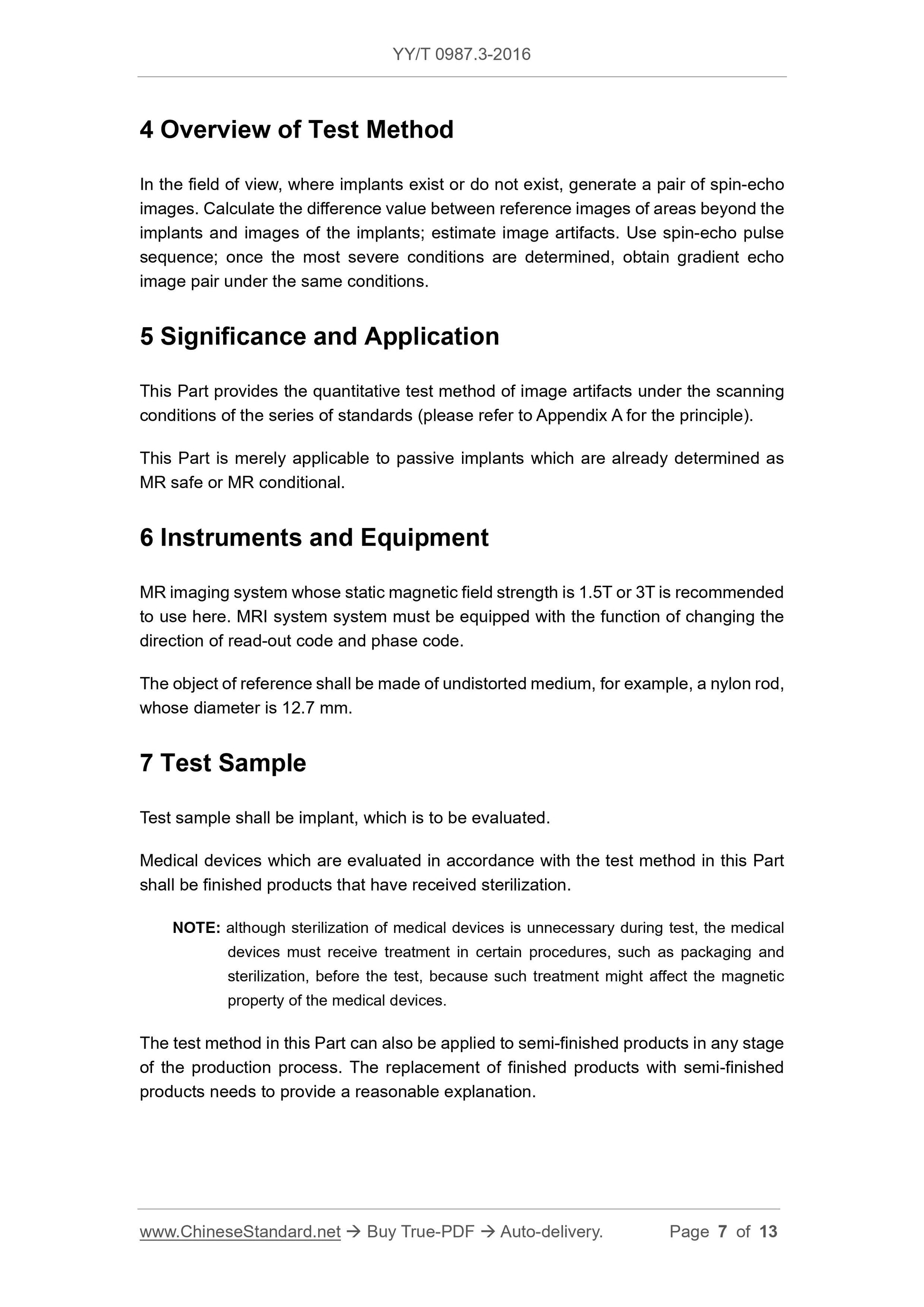
4 Overview of test methods
A pair of spin echo images are produced with and without implantation in the field of view. Calculate the reference image and implant map outside the implant
Estimate image artifacts by the difference of the image. Using spin echo pulse sequences Once the worst conditions are established, gradient echoes should be obtained under the same conditions
Image pair.
5 Significance and application
This section provides a quantitative test method for image artifacts under standard series of scanning conditions (see Appendix A for principles).
This section only applies to passive implants that have been identified as safe for MR safety or MR specific conditions.
6 Instruments and equipment
An MR imaging system with a static magnetic field strength of 1.5T or 3T is recommended. MRI systems must have a change in read code and phase coding
The function of the code direction.
The reference material is made of an undistorted medium such as a nylon rod having a diameter of 12.7 mm.
7 test samples
The test sample is the implant to be evaluated.
Instruments evaluated according to the test methods in this section shall be finished products that have been sterilized.
Note. It is not necessary to sterilize the device during the test, but the device must be processed through packaging, sterilization, etc. before the test, because these treatments may affect
The magnetic properties of the device.
This part of the test method can also be used for semi-finished products at any stage of the production process. It is reasonable to use semi-finished products instead of finished products.
Description.
8 steps
8.1 MR imaging parameter settings in artifact testing
Artifacts are recommended for evaluation using the following MR imaging test environment. For special equipment, if you have sufficient conditions, you can use other
test environment. Adjusting the field of view, layer thickness, and matrix size allows the pixel size to meet the requirements for accurate artifact measurement. The following are two test environments
For example, one is suitable for small implants such as coronary stents, and the other is suitable for larger implants such as hip prostheses.
Static magnetic field strength. 1.5T
Bandwidth. 32kHz (required)
Fieldofview. should be sufficient to cover the implant and its artifacts
Small implants (such as coronary stents)
Matrix (Matrixsize). 256 × 256
Slicethickness. 3mm
Large implants (such as hip prostheses, etc.)
Matrix (Matrixsize). 256 × 128
Slicethickness. 5mm
Two different pulse sequences used.
Pulse sequence. spin echo
TR. 500ms
TE. 20ms
Pulse sequence. gradient echo
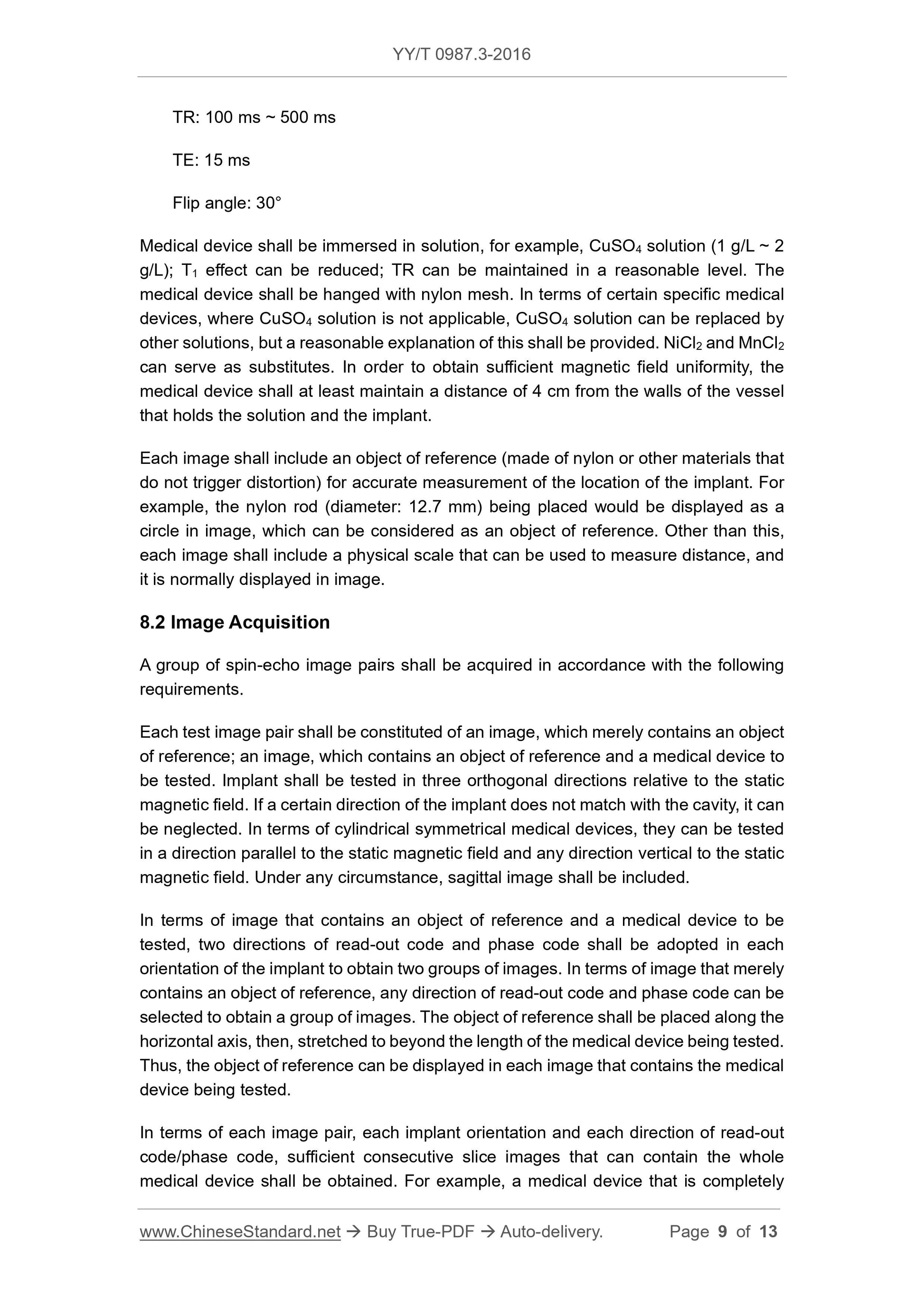
TR. 100ms~500ms
TE. 15ms
Flipangle. 30°
The device should be immersed in a solution, such as copper sulfate (CuSO4) solution (1g/L ~ 2g/L), which can reduce the T1 effect and maintain the TR
On the level of reason. The device is suspended with a nylon mesh. Not applicable to some special instruments such as copper sulfate solution, other solutions can be used instead
For reasonable explanation. Nickel chloride (NiCl2) and manganese chloride (MnCl2) can be used as substitutes. In order to obtain sufficient magnetic field uniformity, the instrument and Sheng
The wall of the container in which the solution and implant are placed should be at least 4 cm apart.
Each image should contain a reference (nylon or other material that does not cause distortion) for accurate measurement of the position of the implant. example
For example, a nylon rod with a diameter of 12.7 mm is placed in the image as a circle, which can be used as a reference. In addition to each, each figure
A physical scale that should contain a measurable distance, usually displayed on the image.
8.2 Image Acquisition
A set of spin echo image pairs should be obtained as follows.
Each test image pair consists of an image with only a reference and an image containing both a reference and a test instrument. Implant
The object should be tested in three orthogonal directions relative to the static magnetic field. If the orientation of the implant does not match the cavity, it can be ignored. Pair of cylindrical pairs
The device is said to be tested in a direction parallel to the static magnetic field and in any direction perpendicular to the static magnetic field. In all cases, it should be included
Sagittal image.
For images containing both the reference and the test instrument, two read and phase encodings should be used for each orientation of the implant.
Get two sets of images in the direction. For an image with only a reference object, a readout code and a phase encoding direction can be arbitrarily selected to acquire a set of images.
The reference is placed along the horizontal axis and extends beyond the length of the instrument under test so that the reference can be displayed on each of the images containing the test instrument
Like in.
For each image pair, each implant orientation, and each read/phase encoding direction, obtain enough for the entire instrument to be included
Slice images in succession. For example, a device that is completely contained in one slice has 3 different orientations × 2 read/phase encoding directions = 6
The image containing the implant 3 images contains only the image of the reference.
The imaging condition (orientation, readout/phase encoding direction, number of layers) for obtaining the worst (artifact maximum) spin echo image group should be used to obtain the ladder
Degree echo sequence image. Imaging at the location where the spin echo image is acquired is perhaps the most efficient.
8.3 Artifact size measurement
The distance (mm) from the edge of the implant to the edge of the artifact (±30% area) is measured. Multiply pixels by field of view (FOV) and matrix (M)
The ratio is calculated as the distance (mm) and the field of view is in meters (m) or millimeters (mm). Distance (mm) = distance (pixels) × FOV/M. Also available
The system console software associated with the MRI scanner measures the distance. Visually check the console or film image if needed, but
In the case of the definition of artifact edges, a conservative definition should be used to ensure that the artifact size is not underestimated. For each image, when the device borders
When it is clear, the worst case (maximum) distance should be used to characterize the artifact. Worst case (maximum) distance in all images (described earlier) should be used
To characterize artifacts.
If the MRI image consists of a blank implant area surrounded by blank artifact areas, it may cause difficulties in characterization. Implants
The boundaries may not be visible. In this case, the border of the implant may be in the center of the blank, using a ruler or vernier caliper to measure the implant
The size of the object, without MRI measurements, measures the distance from the implant boundary to the edge of the artifact. The ratio of implant boundaries should be related to MRI
The ratio of image distances matches.
9 report
For each test sample, the report should include the following.
a) description of the device product;
b) the model number and batch number of the device;
c) device size (physical size);
d) a gradient echo image pair and a set of representative spin echo images containing the worst artifacts;
e) MRI system construction, model and static magnetic field strength;
f) MRI parameters, including TR, TE, bandwidth, receiver, field of view, matrix, and coils used;
g) methods of measuring artifacts;
h) the artifact width of the spin echo image and the artifact width of the gradient echo image;
i) Solution (and solution concentration) of the immersion device. If the CuSO4 solution is not used, reasonable instructions should be provided.
Appendix A
(informative appendix)
Principle of test method
This part of the test method is used to characterize artifacts generated by passive implants that are safe for MR safety or MR specific conditions. standard
YY/T 0987.2 and YY/T 0987.5 are used to determine the magnetic displacement force and magnetic torque of medical devices in MR environment, respectively.
YY/T 0987.4 was used to determine RF heating during MRI. Although the most common medical devices currently encounter the 1.5TMR system environment,
However, the 3TMR system has entered the market and is becoming more and more popular in clinical applications.
In a given MR environment, the artifacts produced by passive implants have a complex relationship with the size, shape and composition of the implant. Pseudo <...
Get Quotation: Click YY/T 0987.3-2016 (Self-service in 1-minute)
Historical versions (Master-website): YY/T 0987.3-2016
Preview True-PDF (Reload/Scroll-down if blank)
YY/T 0987.3-2016: Implants for Surgery - Magnetic Resonance Compatibility - Part 3: Evaluation of MR Image Artifacts from Passive Implants
YY/T 0987.3-2016
Implants for surgery--Magnetic resonance compatibility--Part 3. Evaluation of MR image artifacts from passive implants
ICS 11.040.40
C35
People's Republic of China Pharmaceutical Industry Standard
Surgical implant magnetic resonance compatibility
Part 3. Image artifact evaluation method
Part 3.EvaluationofMRimageartifactsfrompassiveimplants
Published on.2016-03-23
2017-01-01 implementation
State Food and Drug Administration issued
Content
Foreword I
1 range 1
2 Normative references 1
3 Terms and Definitions 1
4 Test method overview 2
5 Significance and application 2
6 Instruments and equipment 2
7 test sample 2
8 Step 2
9 Report 4
Appendix A (informative) Principles of Test Methods 5
Reference 6
Foreword
YY/T 0987 "Surgical Implant Magnetic Resonance Compatibility" is divided into the following sections.
--- Part 1. Security mark;
--- Part 2. Magnetic displacement force test method;
--- Part 3. Image artifact evaluation method;
--- Part 4. Radiofrequency heating test methods;
--- Part 5. Magnetic torque test method.
This part is the third part of YY/T 0987.
This part is drafted in accordance with the rules given in GB/T 1.1-2009.
This section uses the redrafting method with reference to ASTM F2119-2007 "Standard Test for Evaluation of Passive Implant Magnetic Resonance Imaging Image Artifacts"
Method of preparation.
The technical differences between this part and ASTMF2119-2007 are as follows.
---About the normative reference documents, this part has made technical adjustments to adapt to China's technical conditions, adjustments
The situation is reflected in Chapter 2, “Regulatory Citations”, and the specific adjustments are as follows.
● Replace ASTMF2052-06 with YY/T 0987.2;
● Replace ASTMF2182-11a with YY/T 0987.4;
● Replace ASTMF2213-06 with YY/T 0987.5.
--- Remove Chapter 10, Chapter 11 and X1.4 of ASTMF2119-2007.
Please note that some of the contents of this document may involve patents. The issuing organization of this document is not responsible for identifying these patents.
This part is proposed by the State Food and Drug Administration.
This part is under the jurisdiction of the National Technical Committee for Standardization of Surgical Implants and Orthopedic Devices (SAC/TC110).
This section drafted by. State Food and Drug Administration Tianjin Medical Device Quality Supervision and Inspection Center, minimally invasive medical equipment (Shanghai)
Limited.
The main drafters of this section. Li Jia, Yan Hui, Fan Platinum, Shi Haifeng, Li Junfei.
Surgical implant magnetic resonance compatibility
Part 3. Image artifact evaluation method
1 Scope
This part of YY/T 0987 describes passive implants in magnetic resonance (MR) images (surgery that does not rely on electrical energy or other energy sources)
Distortion and signal loss artifacts caused by the implant). Passive implants that are incapable of determining MR safety or MR specific conditions are not part of this
Part of the category.
2 Normative references
The following documents are indispensable for the application of this document. For dated references, only the dated version applies to this article.
Pieces. For undated references, the latest edition (including all amendments) applies to this document.
YY/T 0987.2 Magnetic resonance compatibility of surgical implants - Part 2. Magnetic displacement test method
YY/T 0987.4 Magnetic resonance compatibility of surgical implants - Part 4. Radio-thermal test method
Surgical implants - Magnetic resonance compatibility - Part 5. Magnetic torque test method
3 Terms and definitions
The following terms and definitions apply to this document.
3.1
Artifact width artifactwidth
The maximum distance from the edge of the implant to the edge of the image artifact it produces, using all of the images obtained in this part of the test method
(mm).
3.2
Image artifact imageartifact
Compared with the reference image without the instrument, if the intensity of the pixel in the image changes by more than 30% when the device is present, the pixel is seen
As part of the image artifacts.
3.3
Magnetic resonance (MR) environment magneticresonance (MR) environment
The space within the 0.5mT (5G) line in the MR system, including the entire three-dimensional space around the MR scanner. When the 0.5mT line is included
When Faraday is inside the cage, the entire space should be considered a magnetic resonance (MR) environment.
3.4
Magnetic resonance imaging magneticresonanceimaging; MRI
An imaging technique that uses a static time-varying magnetic field to resonate the nucleus to obtain a tissue image.
3.5
MR specific conditional safety MR conditional
Objects that do not produce known hazards under specific MR environments and specific operating conditions. The specific MR environment in the magnetic field includes strong magnetic fields
Degree, magnetic field spatial gradient, magnetic field time rate of change (dB/dt), radio frequency (RF) field, and specific absorption rate (SAR), in addition to
Including the special configuration of the object.
3.6
MR safety MR safe
No known hazard is produced in all MR environments.
Note. MR-safe objects include non-conductive, non-magnetic objects such as plastic petri dishes. Whether the object is MR based on scientific theory rather than experimental data
Safety.
3.7
MR danger MR unsafe
It poses a dangerous object in all MR environments.
Note. MR dangerous objects include magnetic objects such as ferromagnetic scissors.
3.8
Tesla tesla
The international unit of magnetic induction, equivalent to 104 Gauss (G).
4 Overview of test methods
A pair of spin echo images are produced with and without implantation in the field of view. Calculate the reference image and implant map outside the implant
Estimate image artifacts by the difference of the image. Using spin echo pulse sequences Once the worst conditions are established, gradient echoes should be obtained under the same conditions
Image pair.
5 Significance and application
This section provides a quantitative test method for image artifacts under standard series of scanning conditions (see Appendix A for principles).
This section only applies to passive implants that have been identified as safe for MR safety or MR specific conditions.
6 Instruments and equipment
An MR imaging system with a static magnetic field strength of 1.5T or 3T is recommended. MRI systems must have a change in read code and phase coding
The function of the code direction.
The reference material is made of an undistorted medium such as a nylon rod having a diameter of 12.7 mm.
7 test samples
The test sample is the implant to be evaluated.
Instruments evaluated according to the test methods in this section shall be finished products that have been sterilized.
Note. It is not necessary to sterilize the device during the test, but the device must be processed through packaging, sterilization, etc. before the test, because these treatments may affect
The magnetic properties of the device.
This part of the test method can also be used for semi-finished products at any stage of the production process. It is reasonable to use semi-finished products instead of finished products.
Description.
8 steps
8.1 MR imaging parameter settings in artifact testing
Artifacts are recommended for evaluation using the following MR imaging test environment. For special equipment, if you have sufficient conditions, you can use other
test environment. Adjusting the field of view, layer thickness, and matrix size allows the pixel size to meet the requirements for accurate artifact measurement. The following are two test environments
For example, one is suitable for small implants such as coronary stents, and the other is suitable for larger implants such as hip prostheses.
Static magnetic field strength. 1.5T
Bandwidth. 32kHz (required)
Fieldofview. should be sufficient to cover the implant and its artifacts
Small implants (such as coronary stents)
Matrix (Matrixsize). 256 × 256
Slicethickness. 3mm
Large implants (such as hip prostheses, etc.)
Matrix (Matrixsize). 256 × 128
Slicethickness. 5mm
Two different pulse sequences used.
Pulse sequence. spin echo
TR. 500ms
TE. 20ms
Pulse sequence. gradient echo
TR. 100ms~500ms
TE. 15ms
Flipangle. 30°
The device should be immersed in a solution, such as copper sulfate (CuSO4) solution (1g/L ~ 2g/L), which can reduce the T1 effect and maintain the TR
On the level of reason. The device is suspended with a nylon mesh. Not applicable to some special instruments such as copper sulfate solution, other solutions can be used instead
For reasonable explanation. Nickel chloride (NiCl2) and manganese chloride (MnCl2) can be used as substitutes. In order to obtain sufficient magnetic field uniformity, the instrument and Sheng
The wall of the container in which the solution and implant are placed should be at least 4 cm apart.
Each image should contain a reference (nylon or other material that does not cause distortion) for accurate measurement of the position of the implant. example
For example, a nylon rod with a diameter of 12.7 mm is placed in the image as a circle, which can be used as a reference. In addition to each, each figure
A physical scale that should contain a measurable distance, usually displayed on the image.
8.2 Image Acquisition
A set of spin echo image pairs should be obtained as follows.
Each test image pair consists of an image with only a reference and an image containing both a reference and a test instrument. Implant
The object should be tested in three orthogonal directions relative to the static magnetic field. If the orientation of the implant does not match the cavity, it can be ignored. Pair of cylindrical pairs
The device is said to be tested in a direction parallel to the static magnetic field and in any direction perpendicular to the static magnetic field. In all cases, it should be included
Sagittal image.
For images containing both the reference and the test instrument, two read and phase encodings should be used for each orientation of the implant.
Get two sets of images in the direction. For an image with only a reference object, a readout code and a phase encoding direction can be arbitrarily selected to acquire a set of images.
The reference is placed along the horizontal axis and extends beyond the length of the instrument under test so that the reference can be displayed on each of the images containing the test instrument
Like in.
For each image pair, each implant orientation, and each read/phase encoding direction, obtain enough for the entire instrument to be included
Slice images in succession. For example, a device that is completely contained in one slice has 3 different orientations × 2 read/phase encoding directions = 6
The image containing the implant 3 images contains only the image of the reference.
The imaging condition (orientation, readout/phase encoding direction, number of layers) for obtaining the worst (artifact maximum) spin echo image group should be used to obtain the ladder
Degree echo sequence image. Imaging at the location where the spin echo image is acquired is perhaps the most efficient.
8.3 Artifact size measurement
The distance (mm) from the edge of the implant to the edge of the artifact (±30% area) is measured. Multiply pixels by field of view (FOV) and matrix (M)
The ratio is calculated as the distance (mm) and the field of view is in meters (m) or millimeters (mm). Distance (mm) = distance (pixels) × FOV/M. Also available
The system console software associated with the MRI scanner measures the distance. Visually check the console or film image if needed, but
In the case of the definition of artifact edges, a conservative definition should be used to ensure that the artifact size is not underestimated. For each image, when the device borders
When it is clear, the worst case (maximum) distance should be used to characterize the artifact. Worst case (maximum) distance in all images (described earlier) should be used
To characterize artifacts.
If the MRI image consists of a blank implant area surrounded by blank artifact areas, it may cause difficulties in characterization. Implants
The boundaries may not be visible. In this case, the border of the implant may be in the center of the blank, using a ruler or vernier caliper to measure the implant
The size of the object, without MRI measurements, measures the distance from the implant boundary to the edge of the artifact. The ratio of implant boundaries should be related to MRI
The ratio of image distances matches.
9 report
For each test sample, the report should include the following.
a) description of the device product;
b) the model number and batch number of the device;
c) device size (physical size);
d) a gradient echo image pair and a set of representative spin echo images containing the worst artifacts;
e) MRI system construction, model and static magnetic field strength;
f) MRI parameters, including TR, TE, bandwidth, receiver, field of view, matrix, and coils used;
g) methods of measuring artifacts;
h) the artifact width of the spin echo image and the artifact width of the gradient echo image;
i) Solution (and solution concentration) of the immersion device. If the CuSO4 solution is not used, reasonable instructions should be provided.
Appendix A
(informative appendix)
Principle of test method
This part of the test method is used to characterize artifacts generated by passive implants that are safe for MR safety or MR specific conditions. standard
YY/T 0987.2 and YY/T 0987.5 are used to determine the magnetic displacement force and magnetic torque of medical devices in MR environment, respectively.
YY/T 0987.4 was used to determine RF heating during MRI. Although the most common medical devices currently encounter the 1.5TMR system environment,
However, the 3TMR system has entered the market and is becoming more and more popular in clinical applications.
In a given MR environment, the artifacts produced by passive implants have a complex relationship with the size, shape and composition of the implant. Pseudo <...
Share