1
/
of
12
PayPal, credit cards. Download editable-PDF & invoice in 1 second!
YY/T 1095-2015 English PDF (YY/T1095-2015)
YY/T 1095-2015 English PDF (YY/T1095-2015)
Regular price
$165.00 USD
Regular price
Sale price
$165.00 USD
Unit price
/
per
Shipping calculated at checkout.
Couldn't load pickup availability
Delivery: 3 seconds. Download true-PDF + Invoice.
Get Quotation: Click YY/T 1095-2015 (Self-service in 1-minute)
Historical versions (Master-website): YY/T 1095-2015
Preview True-PDF (Reload/Scroll-down if blank)
YY/T 1095-2015: Myoelectric Biofeedback Equipment
YY/T 1095-2015
Myoelectric biofeedback equipment
ICS 11.040.60
C42
People's Republic of China pharmaceutical industry standards
Replacing YY/T 1095-2007
EMG biofeedback instrument
Issued on. 2015-03-02
2016-01-01 implementation
China Food and Drug Administration released
Foreword
This standard was drafted in accordance with GB/T 1.1-2009 given rules.
The standard safety requirements for full implementation of the GB 9706.1-2007 "Medical Electrical Equipment Part 1. General requirements for safety" and
GB 9706.15-2008 "Medical electrical equipment - Part 1-1. General Requirements for Safety Collateral Standard. Safety requirements for medical electrical systems."
Content.
Instead of the standard YY/T 1095-2007 "EMG biofeedback instrument."
This standard YY/T 1095-2007 Comparison with main technical differences are as follows.
--- Modify the scope of this standard (see Chapter 1);
--- Increasing the classification (see Chapter 4);
--- Modify the feedback indication requirements, test methods (see 52, 62, 2007 edition 4.2.7,5.2.);
--- Added feedback threshold requirements and test methods (see 5.3,6.3);
--- Increased the frequency noise suppression requirements and test methods (see 5.4,6.3);
--- Remove the original requirements and test methods for measuring range (2007 Edition 4.2.1,5.3.1);
--- Indication of increased accuracy requirements and test methods (see 5.5.2,6.5.1);
--- Deleted the original sensitivity requirements (2007 Version 4.2.8);
--- Increasing the requirements and test methods for resolution (see 5.5.3,6.5.2);
--- Modify the requirements and test methods for pass band (see 555, 654, 2007 edition 4.2.4,5.3.4...);
--- Increased the requirements and test methods for frequency notch filter (see 5.5.8,6.5.7);
--- Deleted the original isolation requirements (2007 Version 4.2.9);
--- Increased safety requirements (see 5.8);
--- Increased use of the content and requirements specification (see 5.7);
--- Added Appendix Important Legal Information of guidelines and principles (see Appendix A).
Please note that some of the content of this document may involve patents. Release mechanism of the present document does not assume responsibility for the identification of these patents.
This standard was proposed by the China Food and Drug Administration.
This standard by the National Technical Committee of Standardization for medical electrical physical therapy equipment at the Technical Committee (SAC/TC10/SC4) centralized.
This standard was drafted. Tianjin, the State Food and Drug Administration Medical Device Quality Supervision and Inspection Center.
The main drafters of this standard. Juan Yang, Han desert, Duan Chuan Ying, Sun Huili, Liu Hui, Yuan Xiaobing.
This standard replaces the standards previously issued as follows.
--- YY 91095-1999;
--- YY/T 1095-2007.
EMG biofeedback instrument
1 Scope
This standard specifies the EMG biofeedback device (hereinafter referred to as the anti-muscle meter) terms and definitions, classification, requirements, test methods.
3.1 This standard applies to the provisions of the anti-muscle apparatus.
This standard does not apply to the use of a needle electrode EMG recording instruments and EMG evoked potential.
2 Normative references
The following documents for the application of this document is essential. For dated references, only the dated version suitable for use herein
Member. For undated references, the latest edition (including any amendments) applies to this document.
GB 9706.1-2007 Medical electrical equipment - Part 1. General requirements for safety
GB 9706.15-2008 Medical electrical equipment - Part 1-1. General Requirements for Safety Collateral Standard. Safety of medical electrical systems
Claim
GB/T 14710-2009 medical electrical environmental requirements and test methods
GB/T 16886.1-2011 Biological evaluation of medical devices - Part 1. Evaluation of the risk management process and Test
YY 0505-2012 Medical electrical equipment - Part 1-2. General requirements for safety Collateral standard. Electromagnetic compatibility requirements and tests
3 Terms and Definitions
GB 9706.1-2007 defined and the following terms and definitions apply to this document.
3.1
Using a surface electrode EMG collection body as physiological information, and other forms of visual or auditory feedback to the patient, so that patients can learn
Conscious control of their own psychological and physiological activity to treat diseases of the instrument.
3.2
Surface electrode surfaceelectrode
On the skin surface (or cavity surface) for acquiring noninvasive detection of EMG electrodes.
3.3
Display System displaysystem
In addition to the anti-muscle instrument display indicates feedback, but also provides the means to display EMG amplitude.
3.4
Feedback response frequency feedbackresponsefrequencybands
You can achieve the desired feedback response frequency range.
3.5
Feedback threshold feedbackthreshold
Amplitude response to achieve different degrees when.
Category 4
Classification by structure. can be divided into a display system and a display system without anti-muscle apparatus.
5 Requirements
5.1 Working conditions
Shall comply with the manufacturer's specifications; if not specified, shall meet the requirements of Chapter 10 of GB 9706.1-2007.
5.2 feedback indicates
Feedback should comply with instructions 5.7f) use described in the specification.
5.3 feedback threshold accuracy
Feedback threshold shall be specified by the manufacturer, when the center frequency measurement error should not exceed ± 10% of nominal value.
5.4 frequency noise suppression
At the input of the superposition of a muscle group of anti-meter amplitude of 100μV - when frequency sinusoidal signal (peak-valley), the feedback indicates that should not be changed.
5.5 Display System
5.5.1 Overview
Requirements 5.5.2 ~ 5.5.8 applies only to anti-muscle instrument with a display system. 5.5.2 ~ 5.5.8 Technical Specifications shall muscle anti-meter output display
The measurement part.
5.5.2 Indication accuracy
Error is less than ± 10% or ± 2μV, whichever is greater.
5.5.3 Resolution (measurement sensitivity)
≤2μV.
5.5.4 system noise
≤1μV.
5.5.5 passband
Unless otherwise noted manufacturer, muscle anti instrument should not be narrower than the pass band of 20Hz ~ 500Hz (-3dB) (not including depression wave band).
5.5.6 differential input impedance
Greater than 5MΩ.
5.5.7 CMRR
Greater than 100dB.
5.5.8 frequency notch filter
Anti-muscle instrument should 50Hz notch filter, after the amplitude attenuation should not exceed 5μV (peak - valley).
5.6 Appearance
5.6.1 Anti-muscle meter surface should be smooth, it should be clear and accurate identification, no obvious scratches and bumps.
5.6.2 Fasteners should be connected firmly, the knob, the function switch should be installed accurately and reliably adjusted.
5.7 User's Guide
Instructions meet GB 9706.1-2007 and GB 9706.15-2008 (if applicable) at the same time, it should include at least the following
content.
a) anti-muscle instrument technical parameters, including. the magnitude of the measuring range, the measured response feedback band center frequency specified in Table 1
Pilot.
b) for the reusable electrodes cleaning and disinfection methods and replacement cycle.
c) an electrode to make firm contact with the skin to provide placement, pre-treatment of the skin treatment recommendations.
d) the size of the electrode, the shape of the applicable muscles relations, placement of the electrodes and the distance placement recommendations.
e) the proposed use of the environment. sources of RF interference should be shut down or away from the source of the RF transmitter.
f) to deal with anti-muscle instrument in the instructions for use in accordance with Table 2, the feedback indicates different degree feedback response will be described separately.
For only two feedback response of the anti-muscle apparatus, brochures response no response and the initial response of both the feedback response, provide the appropriate
Feedback indicates that description.
Unless otherwise stated the manufacturer, the input signal should be tested according to the test point specified in Table 1, if necessary, these test points can be
Extended to include other characteristic parameter values manufacturers design.
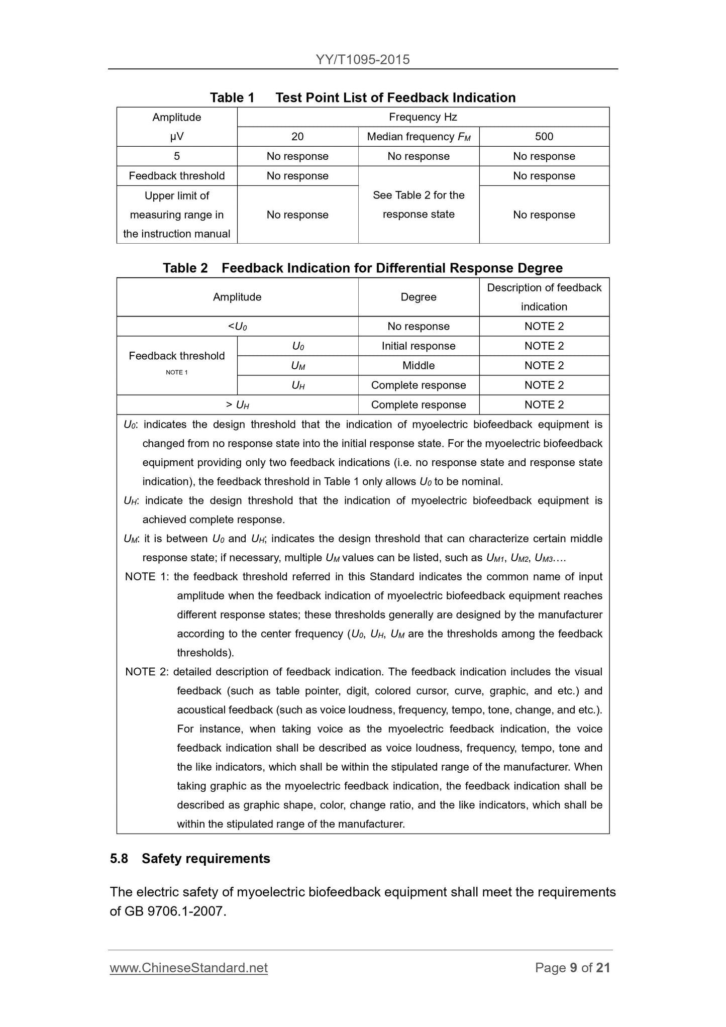
Table 1 lists the test point feedback indicated
Amplitude
μV
frequency
Hz
20 center frequency of FM 500
5 No response No response No response
Feedback threshold No response
Manual measuring range upper limit claimed unresponsive
Table 2 Response Status
No response
No response
Table 2 indicates the different response degree feedback
Description of the amplitude level feedback indicates
\u003cU0 无响应 注2
Feedback threshold Note 1
U0 initial response Note 2
UM intermediate Note 2
UH Complete Response Note 2
TABLE 2 (cont.)
Description of the amplitude level feedback indicates
> UH Complete Response Note 2
U0. refers to the muscle can never respond to anti-instrument indicating the response state to the initial state of the design threshold. For only two kinds of feedback indication (ie no response
Status and response status indication) muscle anti-meter Table 1 feedback threshold allows only nominal U0.
UH. refers to the muscle allows the feedback indicates that the anti-instrument design to achieve the threshold full response status.
UM. between U0 and UH, be able to characterize an intermediate state in response to the design threshold, if necessary, include a plurality of UM values, such as UM1, UM2,
UM3.
Note 1. This standard is mentioned in the feedback threshold is ordered muscle anti-feedback indicating instrument to achieve different input amplitude response extent collectively, these thresholds are usually
Set by the manufacturer (U0, UH, UM feedback threshold are in a certain threshold) according to the center frequency.
Note 2. The feedback indicates detailed description. Feedback indication includes visual feedback (such as a table-type pointer, digital, colored cursor, curve, graphics, etc.) and auditory feedback (eg
Loudness, frequency, rhythm, pitch change, etc.). For example. When using voice instructions as EMG feedback and audible feedback instructions should be described as sound
Sound loudness, frequency, rhythm or tone index within a range specified by the manufacturer. Such as the use of graphics instructions EMG feedback, the feedback means
Should be described as shown in the graphic shapes, colors or graphics change rate index, a range of graphical rate of change should be specified by the manufacturer.
5.8 Safety Requirements
Electrical Safety muscle anti instrument shall meet the requirements of GB 9706.1-2007.
If applicable, the safety of the electrical system shall comply with the requirements of GB 9706.15-2008.
5.9 Environmental test requirements
Environmental testing muscle anti Instrument shall GB/T 14710-2009 regulations.
5.10 biocompatibility
Guide application portion of the material is expected to contact with human skin, it should be in accordance with GB/T 16886.1-2011 and principles given birth
Biocompatibility tests or assessment and documented.
5.11 Electromagnetic compatibility requirements
Anti-muscle instrument shall meet the requirements of YY 0505-2012.
6 Test methods
6.1 Working conditions
6.1.1 Pretreatment
Before the test, the anti-muscle tester should test site parking is not energized at least 24h, before the official test, should press the User's Guide to
Anti muscle seek operation instrument.
6.1.2 Test Environment
See GB 9706.1-2007 requirements in 4.5.
Close or far away from sources of RF interference around.
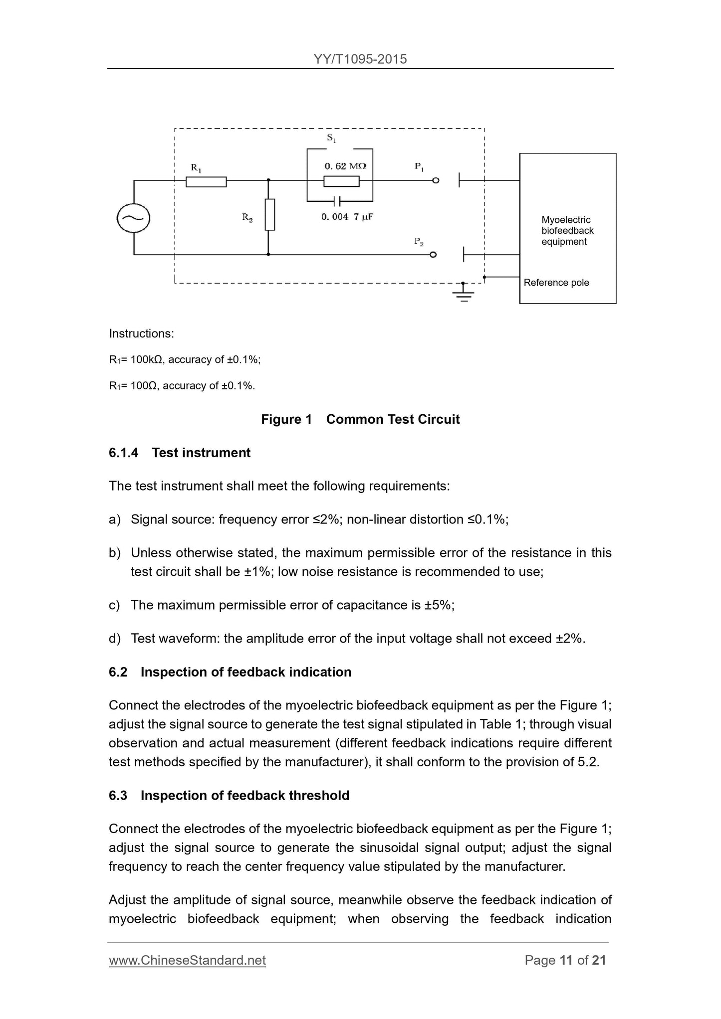
6.1.3 Test circuit
The test circuit is connected as follows.
a) Unless otherwise stated, Figure 1 S1 is normally closed.
b) reference pole (if any) should be grounded.
c) the dotted line in Figure 1 shows the shield case is connected to the ground reference point.
Explanation.
R1 = 100kΩ, an accuracy of ± 0.1%;
R2 = 100Ω, an accuracy of ± 0.1%.
Common test circuit of Figure 1
6.1.4 Test Instruments
Test equipment to meet the following requirements.
a) Source. frequency error ≤2%, nonlinear distortion ≤0.1%;
b) Unless otherwise indicated, the standard test resistance in the circuit of the maximum permissible error of ± 1%, is recommended to use low-noise resistance;
c) the maximum permissible error of capacitance ± 5%;
d) test waveforms. Input voltage amplitude error does not exceed ± 2%.
Check the feedback indicated 6.2
Press muscle anti electrically connected instrument 1, the test signal source generates adjustment signals as specified in Table 1, actually measured or visually (for
Different feedback indication shall be specified by the manufacturer of different test methods), shall comply with the provisions of 5.2.
6.3 feedback detection threshold
Press the electrodes are connected anti-muscle apparatus in FIG. 1, adjust the signal source produces a sinusoidal output signal, adjust the signal frequency to the center frequency specified by the manufacturer
Values.
Adjusting the amplitude of the signal source, while observing the feedback indicates that the anti-muscle instrument, when observed feedback threshold as described in Table 1 corresponding to the feedback means
When shown, the recording signal amplitude at this time with the manufacturer's prescribed feedback threshold comparison, the error should be consistent with the provisions of 5.3.
6.4 inspection frequency noise suppression
Press the electrodes are connected anti-muscle apparatus in FIG. 1, adjust the signal source produces a sinusoidal output signal, adjust the signal frequency to the center frequency specified by the manufacturer
Values.
So muscular anti Tool input amplitude reaches specified by the manufacturer of the feedback threshold U0 above, observe the anti-feedback indicates muscle instrument.
Then at the input of the anti-muscle instrument and then superimposed a magnitude of 100μV (peak - valley) of frequency sinusoidal signals, observe the muscle anti-feedback device means...
Get Quotation: Click YY/T 1095-2015 (Self-service in 1-minute)
Historical versions (Master-website): YY/T 1095-2015
Preview True-PDF (Reload/Scroll-down if blank)
YY/T 1095-2015: Myoelectric Biofeedback Equipment
YY/T 1095-2015
Myoelectric biofeedback equipment
ICS 11.040.60
C42
People's Republic of China pharmaceutical industry standards
Replacing YY/T 1095-2007
EMG biofeedback instrument
Issued on. 2015-03-02
2016-01-01 implementation
China Food and Drug Administration released
Foreword
This standard was drafted in accordance with GB/T 1.1-2009 given rules.
The standard safety requirements for full implementation of the GB 9706.1-2007 "Medical Electrical Equipment Part 1. General requirements for safety" and
GB 9706.15-2008 "Medical electrical equipment - Part 1-1. General Requirements for Safety Collateral Standard. Safety requirements for medical electrical systems."
Content.
Instead of the standard YY/T 1095-2007 "EMG biofeedback instrument."
This standard YY/T 1095-2007 Comparison with main technical differences are as follows.
--- Modify the scope of this standard (see Chapter 1);
--- Increasing the classification (see Chapter 4);
--- Modify the feedback indication requirements, test methods (see 52, 62, 2007 edition 4.2.7,5.2.);
--- Added feedback threshold requirements and test methods (see 5.3,6.3);
--- Increased the frequency noise suppression requirements and test methods (see 5.4,6.3);
--- Remove the original requirements and test methods for measuring range (2007 Edition 4.2.1,5.3.1);
--- Indication of increased accuracy requirements and test methods (see 5.5.2,6.5.1);
--- Deleted the original sensitivity requirements (2007 Version 4.2.8);
--- Increasing the requirements and test methods for resolution (see 5.5.3,6.5.2);
--- Modify the requirements and test methods for pass band (see 555, 654, 2007 edition 4.2.4,5.3.4...);
--- Increased the requirements and test methods for frequency notch filter (see 5.5.8,6.5.7);
--- Deleted the original isolation requirements (2007 Version 4.2.9);
--- Increased safety requirements (see 5.8);
--- Increased use of the content and requirements specification (see 5.7);
--- Added Appendix Important Legal Information of guidelines and principles (see Appendix A).
Please note that some of the content of this document may involve patents. Release mechanism of the present document does not assume responsibility for the identification of these patents.
This standard was proposed by the China Food and Drug Administration.
This standard by the National Technical Committee of Standardization for medical electrical physical therapy equipment at the Technical Committee (SAC/TC10/SC4) centralized.
This standard was drafted. Tianjin, the State Food and Drug Administration Medical Device Quality Supervision and Inspection Center.
The main drafters of this standard. Juan Yang, Han desert, Duan Chuan Ying, Sun Huili, Liu Hui, Yuan Xiaobing.
This standard replaces the standards previously issued as follows.
--- YY 91095-1999;
--- YY/T 1095-2007.
EMG biofeedback instrument
1 Scope
This standard specifies the EMG biofeedback device (hereinafter referred to as the anti-muscle meter) terms and definitions, classification, requirements, test methods.
3.1 This standard applies to the provisions of the anti-muscle apparatus.
This standard does not apply to the use of a needle electrode EMG recording instruments and EMG evoked potential.
2 Normative references
The following documents for the application of this document is essential. For dated references, only the dated version suitable for use herein
Member. For undated references, the latest edition (including any amendments) applies to this document.
GB 9706.1-2007 Medical electrical equipment - Part 1. General requirements for safety
GB 9706.15-2008 Medical electrical equipment - Part 1-1. General Requirements for Safety Collateral Standard. Safety of medical electrical systems
Claim
GB/T 14710-2009 medical electrical environmental requirements and test methods
GB/T 16886.1-2011 Biological evaluation of medical devices - Part 1. Evaluation of the risk management process and Test
YY 0505-2012 Medical electrical equipment - Part 1-2. General requirements for safety Collateral standard. Electromagnetic compatibility requirements and tests
3 Terms and Definitions
GB 9706.1-2007 defined and the following terms and definitions apply to this document.
3.1
Using a surface electrode EMG collection body as physiological information, and other forms of visual or auditory feedback to the patient, so that patients can learn
Conscious control of their own psychological and physiological activity to treat diseases of the instrument.
3.2
Surface electrode surfaceelectrode
On the skin surface (or cavity surface) for acquiring noninvasive detection of EMG electrodes.
3.3
Display System displaysystem
In addition to the anti-muscle instrument display indicates feedback, but also provides the means to display EMG amplitude.
3.4
Feedback response frequency feedbackresponsefrequencybands
You can achieve the desired feedback response frequency range.
3.5
Feedback threshold feedbackthreshold
Amplitude response to achieve different degrees when.
Category 4
Classification by structure. can be divided into a display system and a display system without anti-muscle apparatus.
5 Requirements
5.1 Working conditions
Shall comply with the manufacturer's specifications; if not specified, shall meet the requirements of Chapter 10 of GB 9706.1-2007.
5.2 feedback indicates
Feedback should comply with instructions 5.7f) use described in the specification.
5.3 feedback threshold accuracy
Feedback threshold shall be specified by the manufacturer, when the center frequency measurement error should not exceed ± 10% of nominal value.
5.4 frequency noise suppression
At the input of the superposition of a muscle group of anti-meter amplitude of 100μV - when frequency sinusoidal signal (peak-valley), the feedback indicates that should not be changed.
5.5 Display System
5.5.1 Overview
Requirements 5.5.2 ~ 5.5.8 applies only to anti-muscle instrument with a display system. 5.5.2 ~ 5.5.8 Technical Specifications shall muscle anti-meter output display
The measurement part.
5.5.2 Indication accuracy
Error is less than ± 10% or ± 2μV, whichever is greater.
5.5.3 Resolution (measurement sensitivity)
≤2μV.
5.5.4 system noise
≤1μV.
5.5.5 passband
Unless otherwise noted manufacturer, muscle anti instrument should not be narrower than the pass band of 20Hz ~ 500Hz (-3dB) (not including depression wave band).
5.5.6 differential input impedance
Greater than 5MΩ.
5.5.7 CMRR
Greater than 100dB.
5.5.8 frequency notch filter
Anti-muscle instrument should 50Hz notch filter, after the amplitude attenuation should not exceed 5μV (peak - valley).
5.6 Appearance
5.6.1 Anti-muscle meter surface should be smooth, it should be clear and accurate identification, no obvious scratches and bumps.
5.6.2 Fasteners should be connected firmly, the knob, the function switch should be installed accurately and reliably adjusted.
5.7 User's Guide
Instructions meet GB 9706.1-2007 and GB 9706.15-2008 (if applicable) at the same time, it should include at least the following
content.
a) anti-muscle instrument technical parameters, including. the magnitude of the measuring range, the measured response feedback band center frequency specified in Table 1
Pilot.
b) for the reusable electrodes cleaning and disinfection methods and replacement cycle.
c) an electrode to make firm contact with the skin to provide placement, pre-treatment of the skin treatment recommendations.
d) the size of the electrode, the shape of the applicable muscles relations, placement of the electrodes and the distance placement recommendations.
e) the proposed use of the environment. sources of RF interference should be shut down or away from the source of the RF transmitter.
f) to deal with anti-muscle instrument in the instructions for use in accordance with Table 2, the feedback indicates different degree feedback response will be described separately.
For only two feedback response of the anti-muscle apparatus, brochures response no response and the initial response of both the feedback response, provide the appropriate
Feedback indicates that description.
Unless otherwise stated the manufacturer, the input signal should be tested according to the test point specified in Table 1, if necessary, these test points can be
Extended to include other characteristic parameter values manufacturers design.
Table 1 lists the test point feedback indicated
Amplitude
μV
frequency
Hz
20 center frequency of FM 500
5 No response No response No response
Feedback threshold No response
Manual measuring range upper limit claimed unresponsive
Table 2 Response Status
No response
No response
Table 2 indicates the different response degree feedback
Description of the amplitude level feedback indicates
\u003cU0 无响应 注2
Feedback threshold Note 1
U0 initial response Note 2
UM intermediate Note 2
UH Complete Response Note 2
TABLE 2 (cont.)
Description of the amplitude level feedback indicates
> UH Complete Response Note 2
U0. refers to the muscle can never respond to anti-instrument indicating the response state to the initial state of the design threshold. For only two kinds of feedback indication (ie no response
Status and response status indication) muscle anti-meter Table 1 feedback threshold allows only nominal U0.
UH. refers to the muscle allows the feedback indicates that the anti-instrument design to achieve the threshold full response status.
UM. between U0 and UH, be able to characterize an intermediate state in response to the design threshold, if necessary, include a plurality of UM values, such as UM1, UM2,
UM3.
Note 1. This standard is mentioned in the feedback threshold is ordered muscle anti-feedback indicating instrument to achieve different input amplitude response extent collectively, these thresholds are usually
Set by the manufacturer (U0, UH, UM feedback threshold are in a certain threshold) according to the center frequency.
Note 2. The feedback indicates detailed description. Feedback indication includes visual feedback (such as a table-type pointer, digital, colored cursor, curve, graphics, etc.) and auditory feedback (eg
Loudness, frequency, rhythm, pitch change, etc.). For example. When using voice instructions as EMG feedback and audible feedback instructions should be described as sound
Sound loudness, frequency, rhythm or tone index within a range specified by the manufacturer. Such as the use of graphics instructions EMG feedback, the feedback means
Should be described as shown in the graphic shapes, colors or graphics change rate index, a range of graphical rate of change should be specified by the manufacturer.
5.8 Safety Requirements
Electrical Safety muscle anti instrument shall meet the requirements of GB 9706.1-2007.
If applicable, the safety of the electrical system shall comply with the requirements of GB 9706.15-2008.
5.9 Environmental test requirements
Environmental testing muscle anti Instrument shall GB/T 14710-2009 regulations.
5.10 biocompatibility
Guide application portion of the material is expected to contact with human skin, it should be in accordance with GB/T 16886.1-2011 and principles given birth
Biocompatibility tests or assessment and documented.
5.11 Electromagnetic compatibility requirements
Anti-muscle instrument shall meet the requirements of YY 0505-2012.
6 Test methods
6.1 Working conditions
6.1.1 Pretreatment
Before the test, the anti-muscle tester should test site parking is not energized at least 24h, before the official test, should press the User's Guide to
Anti muscle seek operation instrument.
6.1.2 Test Environment
See GB 9706.1-2007 requirements in 4.5.
Close or far away from sources of RF interference around.
6.1.3 Test circuit
The test circuit is connected as follows.
a) Unless otherwise stated, Figure 1 S1 is normally closed.
b) reference pole (if any) should be grounded.
c) the dotted line in Figure 1 shows the shield case is connected to the ground reference point.
Explanation.
R1 = 100kΩ, an accuracy of ± 0.1%;
R2 = 100Ω, an accuracy of ± 0.1%.
Common test circuit of Figure 1
6.1.4 Test Instruments
Test equipment to meet the following requirements.
a) Source. frequency error ≤2%, nonlinear distortion ≤0.1%;
b) Unless otherwise indicated, the standard test resistance in the circuit of the maximum permissible error of ± 1%, is recommended to use low-noise resistance;
c) the maximum permissible error of capacitance ± 5%;
d) test waveforms. Input voltage amplitude error does not exceed ± 2%.
Check the feedback indicated 6.2
Press muscle anti electrically connected instrument 1, the test signal source generates adjustment signals as specified in Table 1, actually measured or visually (for
Different feedback indication shall be specified by the manufacturer of different test methods), shall comply with the provisions of 5.2.
6.3 feedback detection threshold
Press the electrodes are connected anti-muscle apparatus in FIG. 1, adjust the signal source produces a sinusoidal output signal, adjust the signal frequency to the center frequency specified by the manufacturer
Values.
Adjusting the amplitude of the signal source, while observing the feedback indicates that the anti-muscle instrument, when observed feedback threshold as described in Table 1 corresponding to the feedback means
When shown, the recording signal amplitude at this time with the manufacturer's prescribed feedback threshold comparison, the error should be consistent with the provisions of 5.3.
6.4 inspection frequency noise suppression
Press the electrodes are connected anti-muscle apparatus in FIG. 1, adjust the signal source produces a sinusoidal output signal, adjust the signal frequency to the center frequency specified by the manufacturer
Values.
So muscular anti Tool input amplitude reaches specified by the manufacturer of the feedback threshold U0 above, observe the anti-feedback indicates muscle instrument.
Then at the input of the anti-muscle instrument and then superimposed a magnitude of 100μV (peak - valley) of frequency sinusoidal signals, observe the muscle anti-feedback device means...
Share