


1
/
of
12
PayPal, credit cards. Download editable-PDF & invoice in 1 second!
YY/T 1587-2018 English PDF (YYT1587-2018)
YY/T 1587-2018 English PDF (YYT1587-2018)
Regular price
$145.00 USD
Regular price
Sale price
$145.00 USD
Unit price
/
per
Shipping calculated at checkout.
Couldn't load pickup availability
Delivery: 3 seconds. Download true-PDF + Invoice.
Get Quotation: Click YY/T 1587-2018 (Self-service in 1-minute)
Historical versions (Master-website): YY/T 1587-2018
Preview True-PDF (Reload/Scroll-down if blank)
YY/T 1587-2018: Medical endoscopes - Video endoscopes
YY/T 1587-2018
Medical endoscopes--Video endoscopes
ICS 11.040.99
C40
People's Republic of China Pharmaceutical Industry Standard
Medical endoscope electronic endoscope
Published on.2018-06-26
2019-07-01 implementation
State Drug Administration issued
Content
Foreword III
1 range 1
2 Normative references 1
3 Terms and Definitions 1
4 Requirements 3
5 Test method 5
Appendix A (Normative) Test Method for Luminance Response Characteristics 7
Appendix B (Normative Appendix) Signal to Noise Ratio Test Method 11
Appendix C (Normative Appendix) Test Method for Spatial Frequency Response 14
Appendix D (Normative Appendix) Test Method for Static Image Tolerance 19
Foreword
This standard was drafted in accordance with the rules given in GB/T 1.1-2009.
Please note that some of the contents of this document may involve patents. The issuing organization of this document is not responsible for identifying these patents.
This standard was proposed by the State Drug Administration.
This standard is under the jurisdiction of the National Technical Committee for Standardization of Medical Optics and Instruments (SAC/TC103/SC1).
This standard was drafted. Zhejiang Medical Device Inspection Institute.
The main drafters of this standard. Yan Qinglai, Jia Xiaohang, Zhang Yiyuan, Shen Huanbo, Luo Yongjie, Xu Zhangheng, He Tao, Zheng Jian.
Medical endoscope electronic endoscope
1 Scope
This standard specifies the terms and definitions, requirements, and test methods for medical electronic endoscopes.
This standard applies to medical electronic endoscopes (hereinafter referred to as electronic endoscopes) for visible spectrum imaging in endoscopy and surgery.
This standard does not apply to medical electronic endoscopes for special spectral and non-visible spectral imaging.
2 Normative references
The following documents are indispensable for the application of this document. For dated references, only dated versions apply to this article.
Pieces. For undated references, the latest edition (including all amendments) applies to this document.
GB 9706.19 Medical electrical equipment - Part 2. Particular requirements for safety of endoscopes
GB/T 14233.1-2008 Methods of test for infusions, blood trans
GB/T 16886.1 Biological evaluation of medical devices - Part 1. Evaluation and testing in the process of risk management
Medical endoscopes - Endoscopes - Part 1 . Optical performance and test methods
Medical endoscopes - Endoscopes - Part 2. Mechanical properties and test methods
3 Terms and definitions
The following terms and definitions apply to this document.
3.1
Conversion function conversionfunction
The conversion relationship between different variables.
3.1.1
Optoelectronic conversion function opto-electronicconversionfunction; OECF
The ideal relationship between the brightness of the electronic endoscope and the corresponding output signal.
3.1.2
Electro-optical conversion function elec-optoconversionfunction
OECF inverse function.
3.2
Noise noise
The electronic endoscope responds to disturbances generated internally in the signal.
3.2.1
Overall noise totalnoise
A superposition of fixed mode noise and random noise.
3.2.2
Fixed mode noise fixedpatternnoise
The difference in output signals between the surface sensor units.
3.2.3
Random noise temporalyvaryingnoise
The difference in output signal between multiple exposures of a unit of a surface sensor.
3.3
Signal-to-noise ratio signal-to-noiseratio
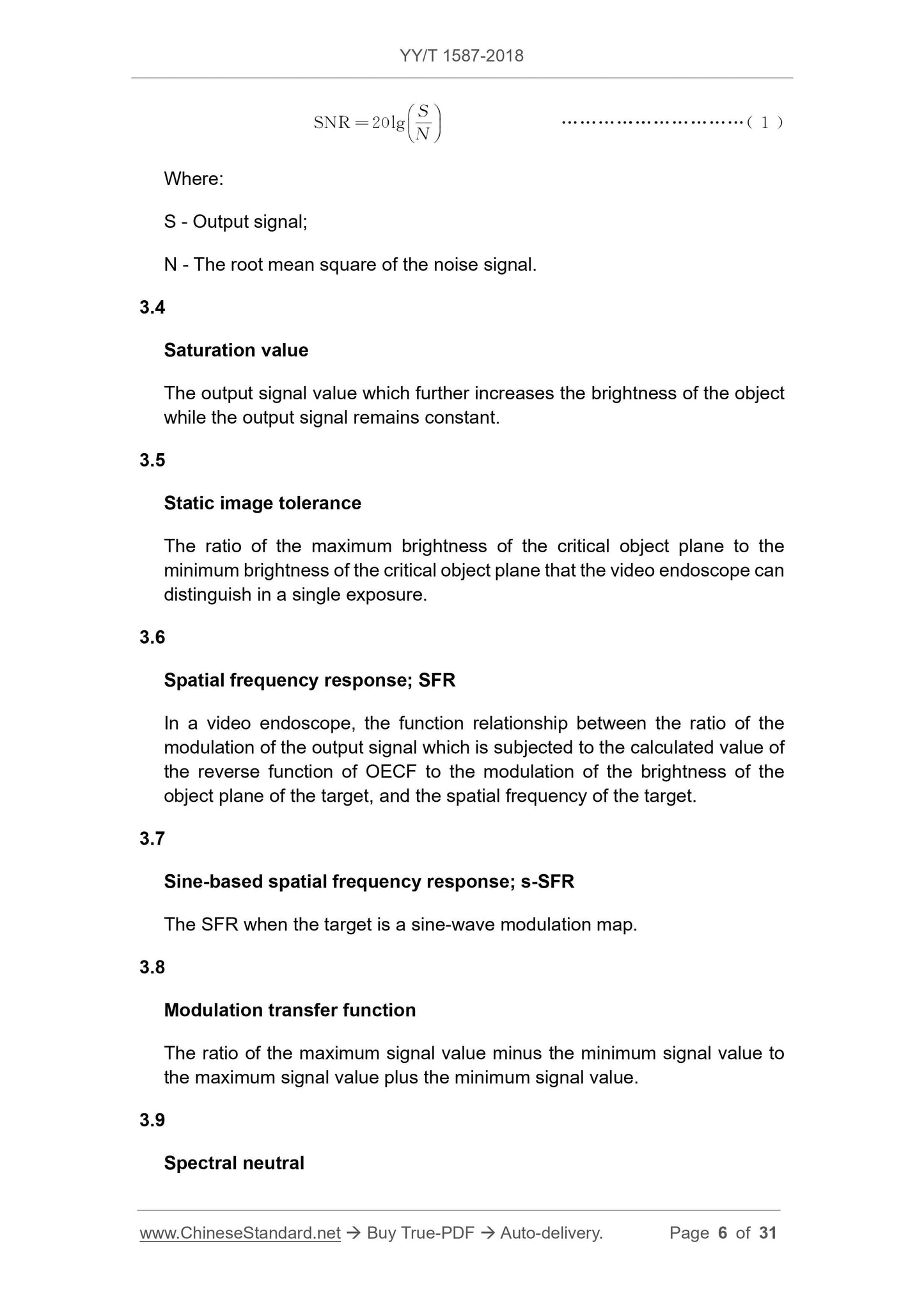
At a particular signal level, the ratio of the output signal to the root mean square value (rms) of the noise signal is represented by a logarithmic value. See expression (1) for the expression.
SNR=20lg
÷ (1)
In the formula.
S---output signal;
N---the noise signal rms value.
3.4
Saturation value
The output signal value is further increased by the brightness of the object while the output signal remains constant.
3.5
Static image latitude staticimagetolerance
The ratio of the maximum critical surface brightness and the minimum critical surface brightness that the electronic endoscope can distinguish in a single exposure.
3.6
Spatial frequency response spatialfrequencyresponse; SFR
In an electronic endoscope, the ratio of the degree of modulation of the output signal to the calculated value of the object surface brightness by the OECF inverse function, and
A functional relationship between the standard space frequencies.
3.7
Sinusoidal based spatial frequency response sine-basedspatialfrequencyresponse;s-SFR
SFR when the target is a sine wave modulation map.
3.8
Modulation modulationfunction
The maximum signal value is subtracted from the ratio between the minimum signal value and the maximum signal value plus the minimum signal value.
3.9
Spectral neutral spectralyneutral
A reflection or transmission characteristic that remains constant for light in a certain band.
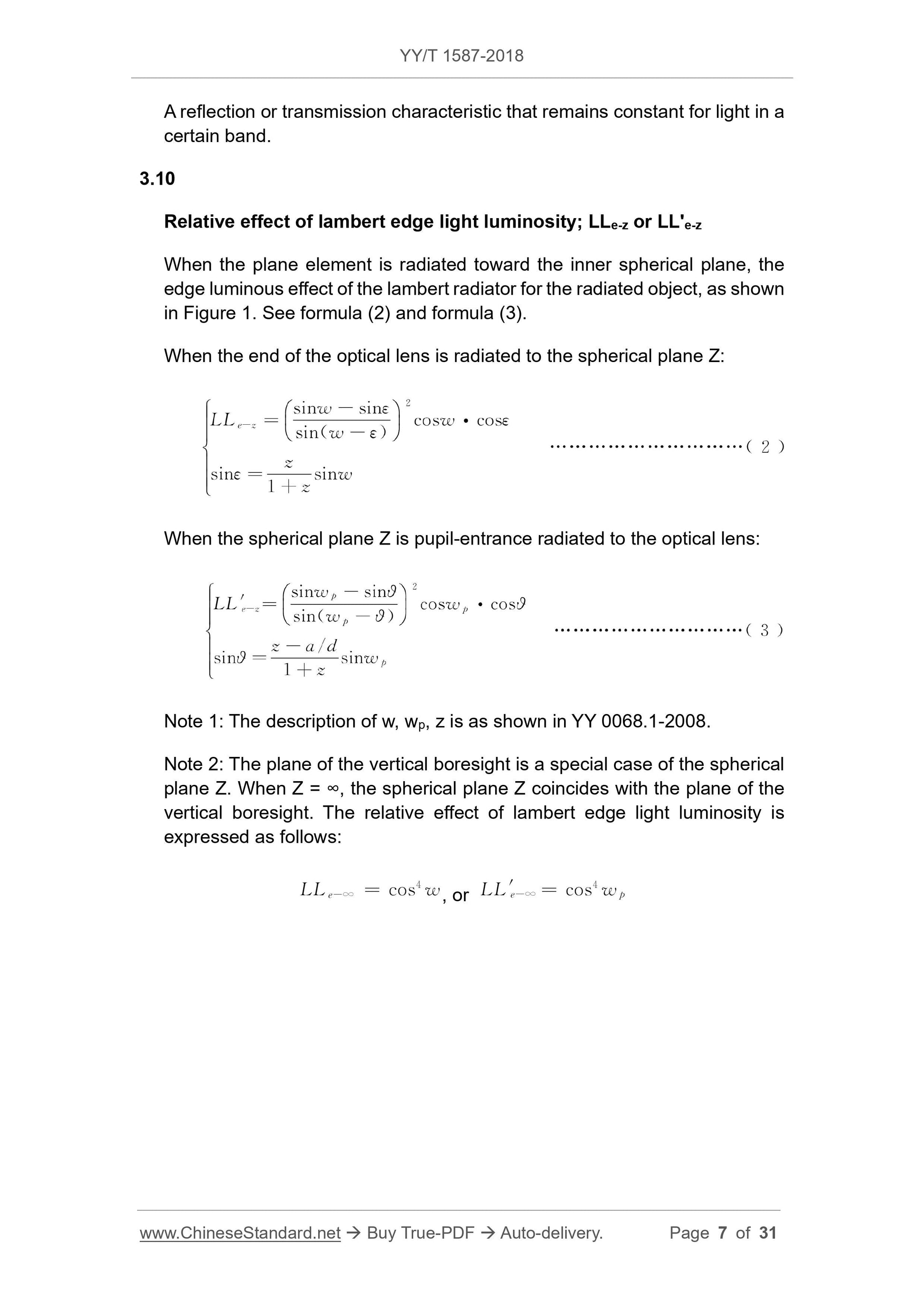
3.10
Lambert light effect relativeeffectoflambertedgelightluminosity;LLe-z or LL'e-z
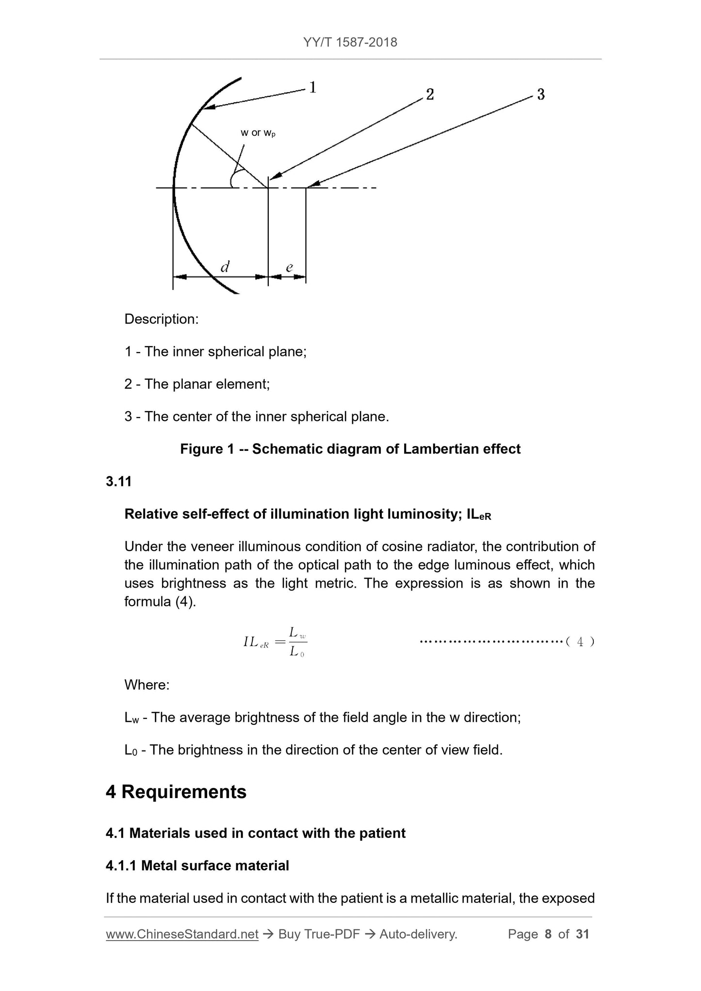
When the plane element is radiated toward the inner spherical surface, the Lambertian radiator has an effect on the edge of the object, as shown in Fig. 1. The formula is shown in equation (2) and
Formula (3).
When the end of the optical mirror is radiated to the spherical surface Z.
LLe-z=
Sinw-sinε
Sin(w-ε)
Cosw·cosε
Sinε=
1 z
Sinw
(2)
When the spherical surface Z is incident on the optical mirror.
LL'e-z=
Sinwp-sinθ
Sin(wp-θ)
Coswp·cosθ
Sinθ=
Za/d
1 z
Sinwp
(3)
Note 1. For the description of w, wp and z in the formula, see YY 0068.1-2008.
Note 2. The plane of the vertical boresight is a special case of the spherical surface Z. When Z=∞, it indicates that the spherical surface Z coincides with the plane of the vertical visual axis, and the Lambertian effect is expressed.
The formula is.
LLe-∞ =cos4w, or LL'e-∞=cos4wp
Description.
1---inner sphere;
2---plane element;
3---The inner spherical surface.
Figure 1 Lambertian light effect diagram
3.11
Illumination mirror body effect relativeself-effectofiluminationlightluminosity; ILeR
Under the condition of cosine radiator veneer illumination, the contribution of the optical path illumination path to the edge light effect is measured by brightness as the light metric. See the expression
Formula (4).
ILeR=
Lw
L0
(4)
In the formula.
Lw --- the average brightness of the field of view w direction;
L0 --- Brightness in the direction of the center of the field of view.
4 requirements
4.1 Materials used in contact with the patient
4.1.1 Metal surface material
If the material used in contact with the patient is a metal material, the exposed part should be consistent with the internal material, if the surface is indeed needed
For coating, the manufacturer shall give the corresponding coating requirements and test methods.
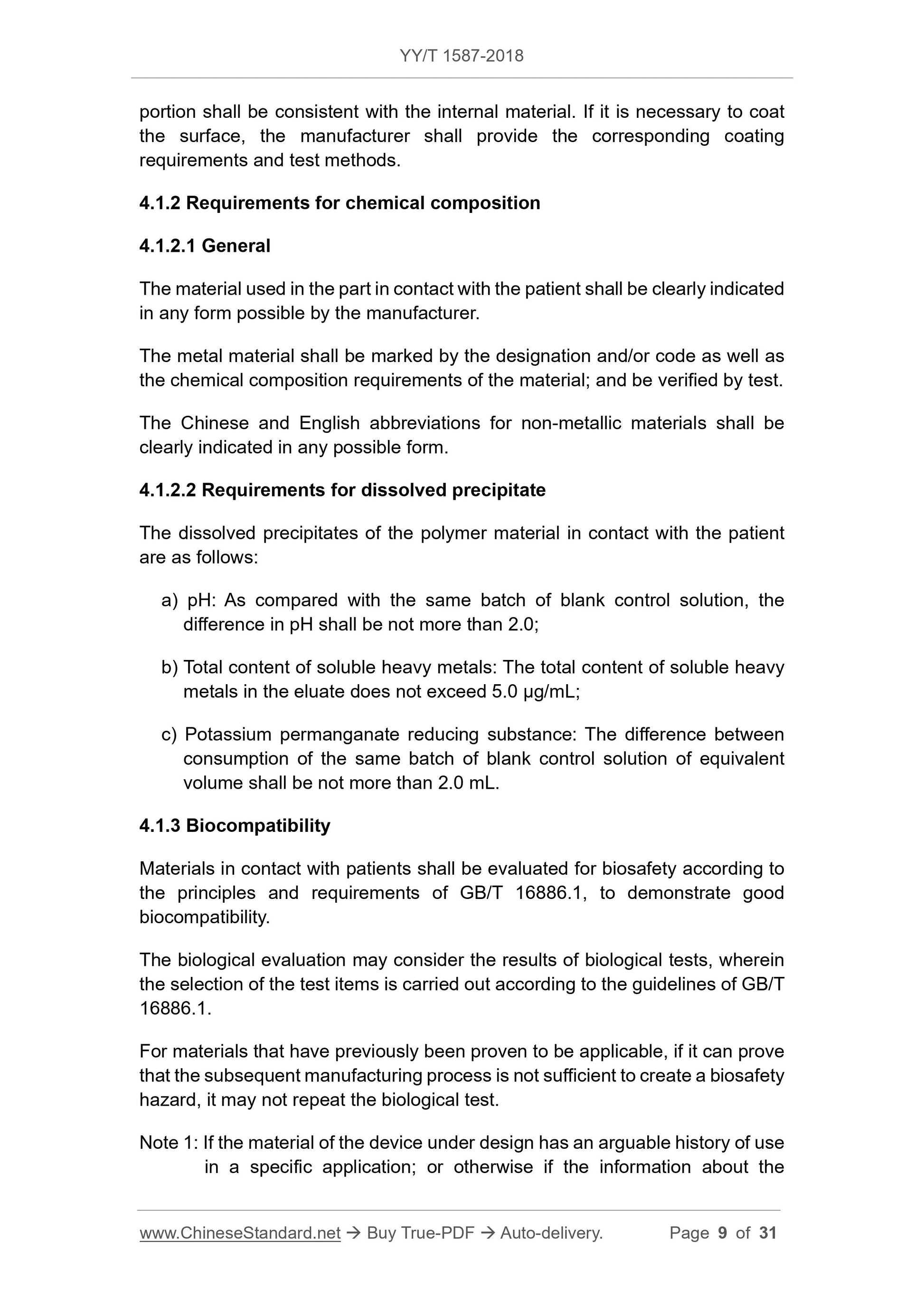
4.1.2 Chemical composition requirements
4.1.2.1 General
The material used in the part in contact with the patient shall be clearly indicated by the manufacturer in any form possible.
The metal material shall be marked with the grade and/or code and the chemical composition requirements of the material and verified by testing.
The Chinese and English short names for non-metallic materials shall be clearly indicated in any possible form.
4.1.2.2 Dissolved precipitate requirements
The dissolved precipitates of the polymer material in contact with the patient are as follows.
a) pH. compared with the same batch of blank control solution, the pH difference should be no more than 2.0;
b) total content of soluble heavy metals. the total content of soluble heavy metals in the eluate does not exceed 5.0 μg/mL;
c) Potassium permanganate reducing substance. the difference between consumption of the same batch of blank control solution should be no more than 2.0mL.
4.1.3 Biocompatibility
Materials in contact with patients should be evaluated for biosafety in accordance with the principles and requirements of GB/T 16886.1 to demonstrate good
Biocompatibility.
The biological evaluation can consider the results of biological tests, and the selection of the test items is carried out according to the guidelines of GB/T 16886.1.
For materials that have previously been proven to be applicable, if it can be demonstrated that the subsequent process of manufacture is not sufficient to create a biosafety hazard,
Repeat the biological test.
Note 1. The material of the device under design has an arguable history of use in a specific application, or information about the material and/or device may be obtained from other sources.
The material has been previously proven to be suitable.
Note 2. If metal materials are used in medical metal materials suitable for the application range of national or industry standards, biological tests may not be repeated.
4.2 Field of view
It should meet the requirements of 4.2.1 field of view in YY 0068.1-2008.
4.3 Lighting mirror effect
The manufacturer shall give the nominal value of the illumination body effect ILeR at the 90% field of view of the wp in the accompanying documentation. Determination of the light effect
The value should be no less than the nominal value.
4.4 Brightness response characteristics
The manufacturer shall give in the technical data an output luminance electro-optic conversion function or data list that is adapted to the monitor in relative values. data
The list has no fewer than 10 sampling points in the latitude area and covers the entire latitude area.
The output of the electronic endoscope output signal according to the electro-optic characteristics should be in good linearity with the gray scale brightness of the actual target.
Degree, the linear fitting coefficient R2 should be not less than 0.98.
If the manufacturer claims that the output brightness and the surface brightness of the adapted monitor are designed in a non-linear fashion, then the manufacturer should give the corresponding
Evaluation requirements and methods.
Note 1. The output brightness of the recommended fit monitor is based on the OECF inverse function of the existing standard.
Note 2. For an electronic endoscope with its own display screen, the linearity requirement refers to the linearity of the brightness of the self-contained screen and the gray scale brightness of the actual measured target board.
4.5 Signal to noise ratio
The manufacturer shall give the nominal value of the random noise signal-to-noise ratio of the electronic endoscope and the corresponding camera mode in the technical data (if the electronic
When the endoscope has multiple camera modes).
The tolerance of the signal to noise ratio is. -20%, and the upper limit is not counted.
4.6 Spatial frequency response
The manufacturer shall give the standard of the angular frequency of the object space corresponding to the electronic endoscope at SFR values of 50% and 30% in the accompanying documents.
The value and the corresponding camera mode (if the electronic endoscope has multiple camera modes).
The tolerance of the angular frequency of the object space corresponding to the SFR value of 50% and 30% is. -20%, and the upper limit is not counted.
4.7 Static image latitude
The manufacturer shall give the nominal value of the static image latitude of the electronic endoscope and the corresponding camera mode in the accompanying materials (if electronic
When the endoscope has multiple camera modes).
The tolerance of the static image latitude is. -20%, and the upper limit is not counted.
4.8 Mechanical properties
The mechanical properties of rigid electronic endoscopes shall comply with the requirements of YY 0068.2.
4.9 Electrical safety
Should meet the requirements of GB 9706.19.
5 Test methods
5.1 Testing of material requirements
5.1.1 Surface material
Visual inspection. For products with a surface coating, follow the appropriate test methods provided by the manufacturer.
5.1.2 Chemical composition test
5.1.2.1 General
The chemical composition and/or bulk structure analysis test of the material is carried out by using a method in which the accuracy is better than or reaches the tolerance or the limit of 1/3.
5.1.2.2 Solubility test
The test solution was prepared in accordance with the sixth method of Table 1 in Chapter 4 of GB/T 14233.1-2008.
The pH is tested in accordance with the method specified in 5.4.1 of GB/T 14233.1-2008.
The total content of soluble heavy metals was tested in accordance with the method specified in 5.6 of GB/T 14233.1-2008.
The potassium permanganate reducing substance was tested in accordance with the method specified in 5.2 of GB/T 14233.1-2008.
5.1.3 Biocompatibility
All tests are preferred to use the relevant standards described in GB/T 16886.1 and are carried out according to their methods.
5.2 Field of view test
It shall be carried out in accordance with the method of measuring the angle of view specified in 5.1 of YY 0068.1-2008.
5.3 Lighting mirror light efficiency test
The electronic endoscope is connected to a light source used by the manufacturer.
The illuminometer window diameter is not more than 90% of the diameter of the field of view band measured by a illuminometer.
The illuminometer window plane should coincide with the selected field of view of the measurement location point.
The illumination body ILER test can be performed by measuring the light intensity on the plane of the vertical boresight or at the end of the endoscope.
The light intensity is measured on the spherical surface formed by the center of the sphere.
The optical working distance measured on the plane is not less than 50 mm; the optical working distance measured on the spherical surface is not less than 77 mm.
The light intensity of the four uniform orientations of the 90% of the wedge of wp must be measured. If the field of view is non-circular, the 4 positions measured are
Diagonal.
When testing on the vertical axis plane, the illuminance of the field of view measured by the illuminometer is recorded as E0.
Calculate the arithmetic mean of the above four azimuth illuminances E1, E2, E3, and E4, and the ratio of the arithm...
Get Quotation: Click YY/T 1587-2018 (Self-service in 1-minute)
Historical versions (Master-website): YY/T 1587-2018
Preview True-PDF (Reload/Scroll-down if blank)
YY/T 1587-2018: Medical endoscopes - Video endoscopes
YY/T 1587-2018
Medical endoscopes--Video endoscopes
ICS 11.040.99
C40
People's Republic of China Pharmaceutical Industry Standard
Medical endoscope electronic endoscope
Published on.2018-06-26
2019-07-01 implementation
State Drug Administration issued
Content
Foreword III
1 range 1
2 Normative references 1
3 Terms and Definitions 1
4 Requirements 3
5 Test method 5
Appendix A (Normative) Test Method for Luminance Response Characteristics 7
Appendix B (Normative Appendix) Signal to Noise Ratio Test Method 11
Appendix C (Normative Appendix) Test Method for Spatial Frequency Response 14
Appendix D (Normative Appendix) Test Method for Static Image Tolerance 19
Foreword
This standard was drafted in accordance with the rules given in GB/T 1.1-2009.
Please note that some of the contents of this document may involve patents. The issuing organization of this document is not responsible for identifying these patents.
This standard was proposed by the State Drug Administration.
This standard is under the jurisdiction of the National Technical Committee for Standardization of Medical Optics and Instruments (SAC/TC103/SC1).
This standard was drafted. Zhejiang Medical Device Inspection Institute.
The main drafters of this standard. Yan Qinglai, Jia Xiaohang, Zhang Yiyuan, Shen Huanbo, Luo Yongjie, Xu Zhangheng, He Tao, Zheng Jian.
Medical endoscope electronic endoscope
1 Scope
This standard specifies the terms and definitions, requirements, and test methods for medical electronic endoscopes.
This standard applies to medical electronic endoscopes (hereinafter referred to as electronic endoscopes) for visible spectrum imaging in endoscopy and surgery.
This standard does not apply to medical electronic endoscopes for special spectral and non-visible spectral imaging.
2 Normative references
The following documents are indispensable for the application of this document. For dated references, only dated versions apply to this article.
Pieces. For undated references, the latest edition (including all amendments) applies to this document.
GB 9706.19 Medical electrical equipment - Part 2. Particular requirements for safety of endoscopes
GB/T 14233.1-2008 Methods of test for infusions, blood trans
GB/T 16886.1 Biological evaluation of medical devices - Part 1. Evaluation and testing in the process of risk management
Medical endoscopes - Endoscopes - Part 1 . Optical performance and test methods
Medical endoscopes - Endoscopes - Part 2. Mechanical properties and test methods
3 Terms and definitions
The following terms and definitions apply to this document.
3.1
Conversion function conversionfunction
The conversion relationship between different variables.
3.1.1
Optoelectronic conversion function opto-electronicconversionfunction; OECF
The ideal relationship between the brightness of the electronic endoscope and the corresponding output signal.
3.1.2
Electro-optical conversion function elec-optoconversionfunction
OECF inverse function.
3.2
Noise noise
The electronic endoscope responds to disturbances generated internally in the signal.
3.2.1
Overall noise totalnoise
A superposition of fixed mode noise and random noise.
3.2.2
Fixed mode noise fixedpatternnoise
The difference in output signals between the surface sensor units.
3.2.3
Random noise temporalyvaryingnoise
The difference in output signal between multiple exposures of a unit of a surface sensor.
3.3
Signal-to-noise ratio signal-to-noiseratio
At a particular signal level, the ratio of the output signal to the root mean square value (rms) of the noise signal is represented by a logarithmic value. See expression (1) for the expression.
SNR=20lg
÷ (1)
In the formula.
S---output signal;
N---the noise signal rms value.
3.4
Saturation value
The output signal value is further increased by the brightness of the object while the output signal remains constant.
3.5
Static image latitude staticimagetolerance
The ratio of the maximum critical surface brightness and the minimum critical surface brightness that the electronic endoscope can distinguish in a single exposure.
3.6
Spatial frequency response spatialfrequencyresponse; SFR
In an electronic endoscope, the ratio of the degree of modulation of the output signal to the calculated value of the object surface brightness by the OECF inverse function, and
A functional relationship between the standard space frequencies.
3.7
Sinusoidal based spatial frequency response sine-basedspatialfrequencyresponse;s-SFR
SFR when the target is a sine wave modulation map.
3.8
Modulation modulationfunction
The maximum signal value is subtracted from the ratio between the minimum signal value and the maximum signal value plus the minimum signal value.
3.9
Spectral neutral spectralyneutral
A reflection or transmission characteristic that remains constant for light in a certain band.
3.10
Lambert light effect relativeeffectoflambertedgelightluminosity;LLe-z or LL'e-z
When the plane element is radiated toward the inner spherical surface, the Lambertian radiator has an effect on the edge of the object, as shown in Fig. 1. The formula is shown in equation (2) and
Formula (3).
When the end of the optical mirror is radiated to the spherical surface Z.
LLe-z=
Sinw-sinε
Sin(w-ε)
Cosw·cosε
Sinε=
1 z
Sinw
(2)
When the spherical surface Z is incident on the optical mirror.
LL'e-z=
Sinwp-sinθ
Sin(wp-θ)
Coswp·cosθ
Sinθ=
Za/d
1 z
Sinwp
(3)
Note 1. For the description of w, wp and z in the formula, see YY 0068.1-2008.
Note 2. The plane of the vertical boresight is a special case of the spherical surface Z. When Z=∞, it indicates that the spherical surface Z coincides with the plane of the vertical visual axis, and the Lambertian effect is expressed.
The formula is.
LLe-∞ =cos4w, or LL'e-∞=cos4wp
Description.
1---inner sphere;
2---plane element;
3---The inner spherical surface.
Figure 1 Lambertian light effect diagram
3.11
Illumination mirror body effect relativeself-effectofiluminationlightluminosity; ILeR
Under the condition of cosine radiator veneer illumination, the contribution of the optical path illumination path to the edge light effect is measured by brightness as the light metric. See the expression
Formula (4).
ILeR=
Lw
L0
(4)
In the formula.
Lw --- the average brightness of the field of view w direction;
L0 --- Brightness in the direction of the center of the field of view.
4 requirements
4.1 Materials used in contact with the patient
4.1.1 Metal surface material
If the material used in contact with the patient is a metal material, the exposed part should be consistent with the internal material, if the surface is indeed needed
For coating, the manufacturer shall give the corresponding coating requirements and test methods.
4.1.2 Chemical composition requirements
4.1.2.1 General
The material used in the part in contact with the patient shall be clearly indicated by the manufacturer in any form possible.
The metal material shall be marked with the grade and/or code and the chemical composition requirements of the material and verified by testing.
The Chinese and English short names for non-metallic materials shall be clearly indicated in any possible form.
4.1.2.2 Dissolved precipitate requirements
The dissolved precipitates of the polymer material in contact with the patient are as follows.
a) pH. compared with the same batch of blank control solution, the pH difference should be no more than 2.0;
b) total content of soluble heavy metals. the total content of soluble heavy metals in the eluate does not exceed 5.0 μg/mL;
c) Potassium permanganate reducing substance. the difference between consumption of the same batch of blank control solution should be no more than 2.0mL.
4.1.3 Biocompatibility
Materials in contact with patients should be evaluated for biosafety in accordance with the principles and requirements of GB/T 16886.1 to demonstrate good
Biocompatibility.
The biological evaluation can consider the results of biological tests, and the selection of the test items is carried out according to the guidelines of GB/T 16886.1.
For materials that have previously been proven to be applicable, if it can be demonstrated that the subsequent process of manufacture is not sufficient to create a biosafety hazard,
Repeat the biological test.
Note 1. The material of the device under design has an arguable history of use in a specific application, or information about the material and/or device may be obtained from other sources.
The material has been previously proven to be suitable.
Note 2. If metal materials are used in medical metal materials suitable for the application range of national or industry standards, biological tests may not be repeated.
4.2 Field of view
It should meet the requirements of 4.2.1 field of view in YY 0068.1-2008.
4.3 Lighting mirror effect
The manufacturer shall give the nominal value of the illumination body effect ILeR at the 90% field of view of the wp in the accompanying documentation. Determination of the light effect
The value should be no less than the nominal value.
4.4 Brightness response characteristics
The manufacturer shall give in the technical data an output luminance electro-optic conversion function or data list that is adapted to the monitor in relative values. data
The list has no fewer than 10 sampling points in the latitude area and covers the entire latitude area.
The output of the electronic endoscope output signal according to the electro-optic characteristics should be in good linearity with the gray scale brightness of the actual target.
Degree, the linear fitting coefficient R2 should be not less than 0.98.
If the manufacturer claims that the output brightness and the surface brightness of the adapted monitor are designed in a non-linear fashion, then the manufacturer should give the corresponding
Evaluation requirements and methods.
Note 1. The output brightness of the recommended fit monitor is based on the OECF inverse function of the existing standard.
Note 2. For an electronic endoscope with its own display screen, the linearity requirement refers to the linearity of the brightness of the self-contained screen and the gray scale brightness of the actual measured target board.
4.5 Signal to noise ratio
The manufacturer shall give the nominal value of the random noise signal-to-noise ratio of the electronic endoscope and the corresponding camera mode in the technical data (if the electronic
When the endoscope has multiple camera modes).
The tolerance of the signal to noise ratio is. -20%, and the upper limit is not counted.
4.6 Spatial frequency response
The manufacturer shall give the standard of the angular frequency of the object space corresponding to the electronic endoscope at SFR values of 50% and 30% in the accompanying documents.
The value and the corresponding camera mode (if the electronic endoscope has multiple camera modes).
The tolerance of the angular frequency of the object space corresponding to the SFR value of 50% and 30% is. -20%, and the upper limit is not counted.
4.7 Static image latitude
The manufacturer shall give the nominal value of the static image latitude of the electronic endoscope and the corresponding camera mode in the accompanying materials (if electronic
When the endoscope has multiple camera modes).
The tolerance of the static image latitude is. -20%, and the upper limit is not counted.
4.8 Mechanical properties
The mechanical properties of rigid electronic endoscopes shall comply with the requirements of YY 0068.2.
4.9 Electrical safety
Should meet the requirements of GB 9706.19.
5 Test methods
5.1 Testing of material requirements
5.1.1 Surface material
Visual inspection. For products with a surface coating, follow the appropriate test methods provided by the manufacturer.
5.1.2 Chemical composition test
5.1.2.1 General
The chemical composition and/or bulk structure analysis test of the material is carried out by using a method in which the accuracy is better than or reaches the tolerance or the limit of 1/3.
5.1.2.2 Solubility test
The test solution was prepared in accordance with the sixth method of Table 1 in Chapter 4 of GB/T 14233.1-2008.
The pH is tested in accordance with the method specified in 5.4.1 of GB/T 14233.1-2008.
The total content of soluble heavy metals was tested in accordance with the method specified in 5.6 of GB/T 14233.1-2008.
The potassium permanganate reducing substance was tested in accordance with the method specified in 5.2 of GB/T 14233.1-2008.
5.1.3 Biocompatibility
All tests are preferred to use the relevant standards described in GB/T 16886.1 and are carried out according to their methods.
5.2 Field of view test
It shall be carried out in accordance with the method of measuring the angle of view specified in 5.1 of YY 0068.1-2008.
5.3 Lighting mirror light efficiency test
The electronic endoscope is connected to a light source used by the manufacturer.
The illuminometer window diameter is not more than 90% of the diameter of the field of view band measured by a illuminometer.
The illuminometer window plane should coincide with the selected field of view of the measurement location point.
The illumination body ILER test can be performed by measuring the light intensity on the plane of the vertical boresight or at the end of the endoscope.
The light intensity is measured on the spherical surface formed by the center of the sphere.
The optical working distance measured on the plane is not less than 50 mm; the optical working distance measured on the spherical surface is not less than 77 mm.
The light intensity of the four uniform orientations of the 90% of the wedge of wp must be measured. If the field of view is non-circular, the 4 positions measured are
Diagonal.
When testing on the vertical axis plane, the illuminance of the field of view measured by the illuminometer is recorded as E0.
Calculate the arithmetic mean of the above four azimuth illuminances E1, E2, E3, and E4, and the ratio of the arithm...
Share