


1
/
of
12
PayPal, credit cards. Download editable-PDF & invoice in 1 second!
YY/T 1671-2020 English PDF (YY/T1671-2020)
YY/T 1671-2020 English PDF (YY/T1671-2020)
Regular price
$175.00 USD
Regular price
Sale price
$175.00 USD
Unit price
/
per
Shipping calculated at checkout.
Couldn't load pickup availability
Delivery: 3 seconds. Download true-PDF + Invoice.
Get Quotation: Click YY/T 1671-2020 (Self-service in 1-minute)
Historical versions (Master-website): YY/T 1671-2020
Preview True-PDF (Reload/Scroll-down if blank)
YY/T 1671-2020: Ultrasound biopsy guide
YY/T 1671-2020
Ultrasound biopsy guide
ICS 11.040.50
C41
People's Republic of China Pharmaceutical Industry Standards
Ultrasound probe puncture frame
2020-02-25 released
2022-03-01 implementation
Issued by the National Medical Products Administration
Preface
This standard was drafted in accordance with the rules given in GB/T 1.1-2009.
Please note that some of the contents of this document may involve patents. Publication of this document
The agency is not responsible for identifying these patents.
This standard was proposed by the State Drug Administration.
This standard is under the jurisdiction of the National Medical Electrical Appliance Standardization Technical Committee Medical Ultrasonic Equipment Subcommittee (SAC/TC10/SC2).
This standard was drafted. Suzhou Lippu Medical Technology Co., Ltd., Hubei Medical Device Quality Supervision and Inspection Institute.
The main drafters of this standard. Wang Baozhong, Wang Qin, Jiang Shilin, Wang Zhijian, Liang Ping, Hu Bing, Xu Huixiong, Gu Wei, Zhu Yu, Jiang Xinhua, Wu Chengzhi.
Ultrasound probe puncture frame
1 Scope
This standard specifies the terms and definitions, structure type and naming, requirements and test methods of the ultrasonic probe puncture frame.
This standard applies to the ultrasound probe puncture frame.
This standard does not apply to induction navigation devices, such as magnetic navigation devices.
2 Normative references
The following documents are indispensable for the application of this document. For dated reference documents, only the dated version applies to this article
Pieces. For undated reference documents, the latest version (including all amendments) is applicable to this document.
GB/T 14233.1-2008 Medical transfusion, blood transfusion, injection equipment inspection methods Part 1.Chemical analysis methods
GB/T 16886.1 Biological Evaluation of Medical Devices Part 1.Evaluation and Testing in the Process of Risk Management
Pharmacopoeia of the People's Republic of China.2015 Edition
3 Terms and definitions
The following terms and definitions apply to this document.
3.1
In ultrasound diagnosis and treatment operations, it is used in conjunction with intracavity or extracorporeal ultrasound probes for puncture needles, drainage tubes, treatment or drug delivery devices
Such as the guiding and fixing device of the puncture instrument.
3.2
In-planepuncture
During the puncture process, the puncture instrument and the sound beam are in the same plane.
3.3
Out-planepuncture
During the puncture process, the puncture instrument and the sound beam are not in the same plane.
4 Structure type and naming
The ultrasonic probe puncture frame is mainly composed of a frame body used to fix the probe and a needle groove channel used to fix and guide the puncture instrument.
According to the positional relationship between the puncture path and the plane of the sound beam, the ultrasonic probe puncture frame is divided into an in-plane puncture frame and an out-of-plane puncture frame.
According to the matched ultrasound probes, the ultrasound probe puncture rack is divided into an extracorporeal ultrasound probe puncture rack and an intracavity ultrasound probe puncture rack.
The ultrasonic probe puncture frame is divided into reusable puncture frame and single-use puncture frame according to different uses.
Several typical structures of the ultrasound probe puncture frame and the names and terms of each part, see Appendix A.
5 requirements
5.1 Appearance
The surface of the puncture frame should be smooth, free of impurities, no sharp edges, no burrs, no sharp corners, etc. The surface of the metal puncture frame should be free of rust spots and oil stains.
The puncture channel of the puncture frame should be smooth and free of burrs.
5.2 Performance
5.2.1 The puncture frame should be able to be firmly installed on the ultrasound probe.
5.2.2 The puncture device should be unobstructed during its travel in the needle slot, and the puncture device should not be shaken obviously.
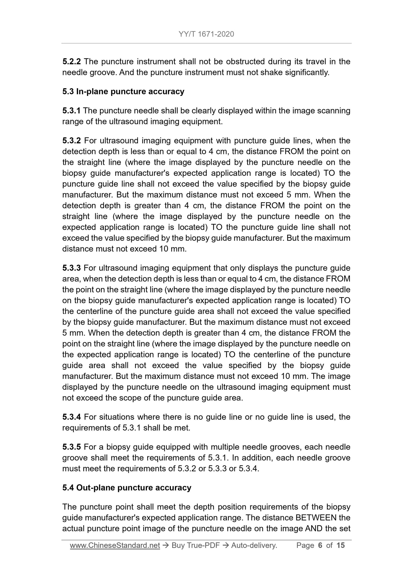
5.3 Puncture accuracy of in-plane puncture
5.3.1 The puncture needle should be clearly displayed within the image scanning range of the ultrasound imaging equipment.
5.3.2 For ultrasound imaging equipment with puncture guide wires, when the detection depth is less than or equal to 4 cm, the puncture needle is set in the puncture frame.
The manufacturer expects that the distance from the point on the straight line of the image displayed on the applicable scope to the puncture guide line should not exceed the number specified by the puncture frame manufacturer.
Value, but the maximum distance must not exceed 5mm; when the detection depth is greater than 4cm, the puncture needle will display on the expected scope of application.
The distance between the point on the line where the image is located and the puncture guide line should not exceed the value specified by the puncture frame manufacturer, but the maximum distance should not exceed the value specified by the puncture frame manufacturer.
Over 10mm.
5.3.3 For ultrasound imaging equipment that only displays the puncture guide area, when the detection depth is less than or equal to 4 cm, the puncture needle is
The frame manufacturer expects that the distance from the point on the straight line where the image displayed on the scope of application is to the center line of the puncture guide area should not exceed the puncture frame system.
The value specified by the manufacturer, but the maximum distance must not exceed 5mm; when the detection depth is greater than 4cm, the puncture needle is expected to be suitable
The distance from the point on the line where the image displayed on the range is to the center line of the puncture guide area should not exceed the value specified by the puncture frame manufacturer.
However, the maximum distance must not exceed 10 mm; the image displayed on the ultrasound imaging device by the puncture needle must not exceed the puncture guide area.
range.
5.3.4 For situations where there is no guide line or no guide line is used, the requirements of 5.3.1 shall be met.
5.3.5 For the puncture frame equipped with multiple needle slots, each of its needle slots should meet the requirements of 5.3.1; in addition, each of its needle slots should also meet the requirements of 5.3.2 or
5.3.3 or 5.3.4.
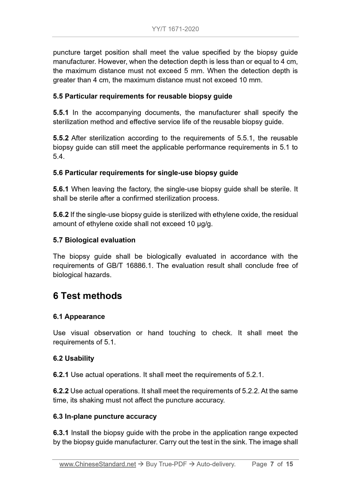
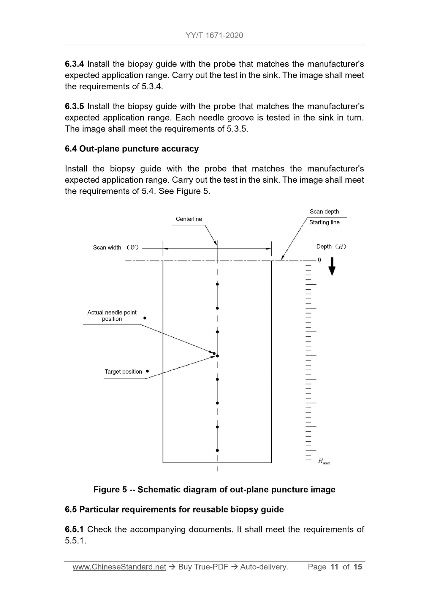
5.4 Puncture accuracy of out-of-plane puncture
The puncture point should meet the depth position requirements of the puncture frame manufacturer's expected scope of application, and the image of the actual puncture point of the puncture needle on the image should be consistent with that of the actual puncture point.
The set distance of the puncture target position should meet the value specified by the puncture frame manufacturer, but when the detection depth is less than or equal to 4cm
, The maximum distance must not exceed 5mm; in the case of detection depth greater than 4cm, the maximum distance must not exceed
10mm.
5.5 Special requirements for reusable puncture racks
5.5.1 The manufacturer shall specify the sterilization method and effective service life of the reusable puncture rack in the accompanying documents.
5.5.2 After sterilization in accordance with the requirements of 5.5.1, the reusable puncture frame can still meet the applicable performance requirements in 5.1 to 5.4.
5.6 Special requirements for single-use puncture racks
5.6.1 The disposable puncture frame should be sterile when it leaves the factory, and it should be sterile after a confirmed sterilization process.
5.6.2 If the disposable puncture frame is sterilized with ethylene oxide, the residual amount of ethylene oxide should not exceed 10 μg/g.
5.7 Biological evaluation
The puncture frame should be biologically evaluated in accordance with the requirements of GB/T 16886.1, and the evaluation result should be free of biological hazards.
6 Test method
6.1 Appearance
Use visual observation or hand touching for inspection, and it should meet the requirements of 5.1.
6.2 Performance
6.2.1 The actual operation should be in accordance with 5.2.1.
6.2.2 The actual operation should meet the requirements of 5.2.2, and its shaking should not affect the puncture accuracy.
6.3 Puncture accuracy of in-plane puncture
6.3.1 The puncture frame and the puncture frame manufacturer's expected installation of the probe on the scope of application, the test is carried out in the sink, and the image should meet the requirements of 5.3.1.
set. When measuring, the image on the manufacturer's expected application range should be adjusted to the best state, and the measurement should be performed at the center of the puncture needle image as much as possible.
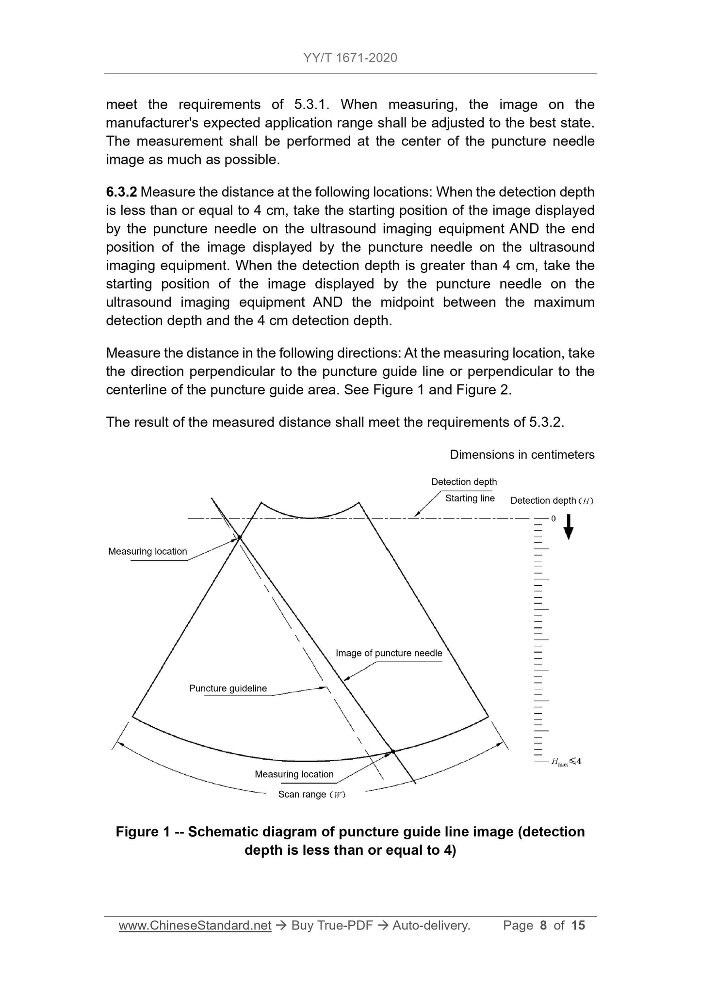
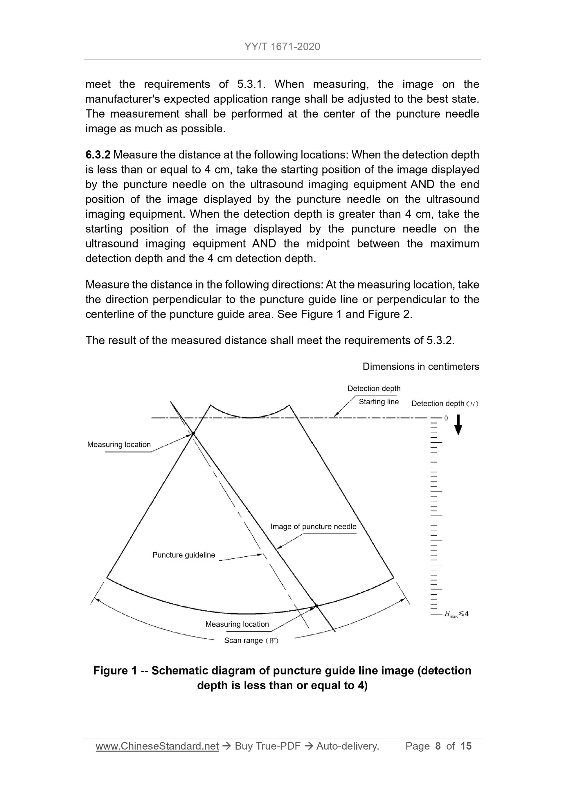
6.3.2 Measure the distance at the following positions. when the detection depth is less than or equal to 4cm, take the puncture needle and display it on the ultrasound imaging device
The starting position of the image and the end position of the image displayed by the puncture needle on the ultrasound imaging device; when the detection depth is greater than 4cm
Next, take the starting position of the image displayed by the puncture needle on the ultrasound imaging device and the midpoint between the maximum detection depth and the 4cm detection depth
Place.
Measure the distance in the following directions. Take the direction perpendicular to the puncture guide line or perpendicular to the center line of the puncture guide area at the measurement position, see
Figure 1 and Figure 2.
The result of the measured distance should meet the requirements of 5.3.2.
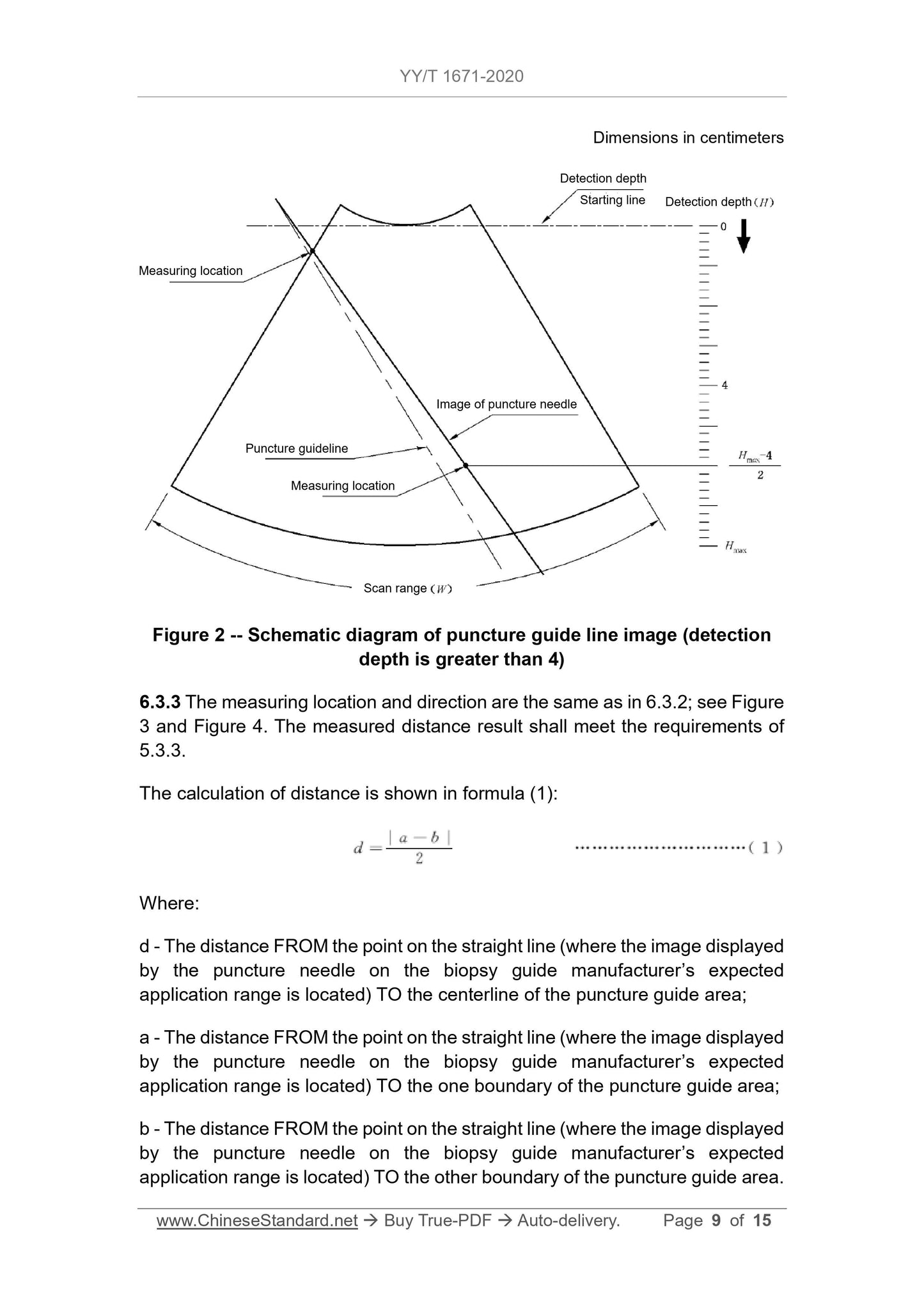
Figure 2 Schematic diagram of puncture guide line image (detection depth greater than 4)
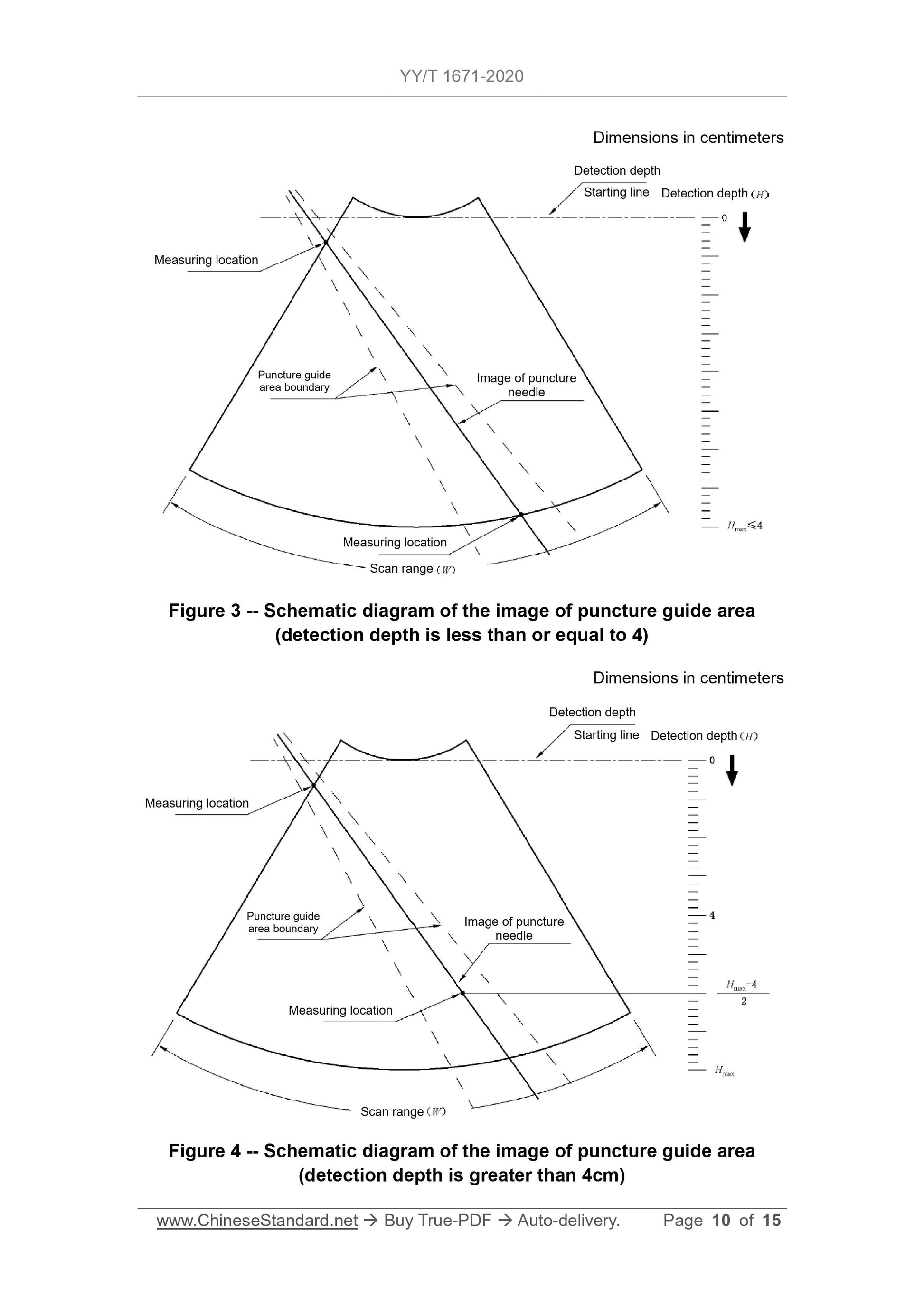
6.3.3 The measurement position and direction are the same as in 6.3.2, see Figure 3 and Figure 4.The measured distance result should meet the requirements of 5.3.3.
The calculation of distance is shown in formula (1).
d=|
ab|
(1)
Where.
d---The point on the straight line of the image displayed on the puncture frame manufacturer's expected application range of the puncture needle to the center line of the puncture guide area
distance;
a ---The point on the straight line where the image displayed on the puncture frame manufacturer's expected application range of the puncture needle is to one side of the puncture guide area
The distance of the boundary;
b ---The point on the straight line of the image displayed on the puncture frame manufacturer's expected application range of the puncture needle to the other side of the puncture guide area
The distance of the border.
Get Quotation: Click YY/T 1671-2020 (Self-service in 1-minute)
Historical versions (Master-website): YY/T 1671-2020
Preview True-PDF (Reload/Scroll-down if blank)
YY/T 1671-2020: Ultrasound biopsy guide
YY/T 1671-2020
Ultrasound biopsy guide
ICS 11.040.50
C41
People's Republic of China Pharmaceutical Industry Standards
Ultrasound probe puncture frame
2020-02-25 released
2022-03-01 implementation
Issued by the National Medical Products Administration
Preface
This standard was drafted in accordance with the rules given in GB/T 1.1-2009.
Please note that some of the contents of this document may involve patents. Publication of this document
The agency is not responsible for identifying these patents.
This standard was proposed by the State Drug Administration.
This standard is under the jurisdiction of the National Medical Electrical Appliance Standardization Technical Committee Medical Ultrasonic Equipment Subcommittee (SAC/TC10/SC2).
This standard was drafted. Suzhou Lippu Medical Technology Co., Ltd., Hubei Medical Device Quality Supervision and Inspection Institute.
The main drafters of this standard. Wang Baozhong, Wang Qin, Jiang Shilin, Wang Zhijian, Liang Ping, Hu Bing, Xu Huixiong, Gu Wei, Zhu Yu, Jiang Xinhua, Wu Chengzhi.
Ultrasound probe puncture frame
1 Scope
This standard specifies the terms and definitions, structure type and naming, requirements and test methods of the ultrasonic probe puncture frame.
This standard applies to the ultrasound probe puncture frame.
This standard does not apply to induction navigation devices, such as magnetic navigation devices.
2 Normative references
The following documents are indispensable for the application of this document. For dated reference documents, only the dated version applies to this article
Pieces. For undated reference documents, the latest version (including all amendments) is applicable to this document.
GB/T 14233.1-2008 Medical transfusion, blood transfusion, injection equipment inspection methods Part 1.Chemical analysis methods
GB/T 16886.1 Biological Evaluation of Medical Devices Part 1.Evaluation and Testing in the Process of Risk Management
Pharmacopoeia of the People's Republic of China.2015 Edition
3 Terms and definitions
The following terms and definitions apply to this document.
3.1
In ultrasound diagnosis and treatment operations, it is used in conjunction with intracavity or extracorporeal ultrasound probes for puncture needles, drainage tubes, treatment or drug delivery devices
Such as the guiding and fixing device of the puncture instrument.
3.2
In-planepuncture
During the puncture process, the puncture instrument and the sound beam are in the same plane.
3.3
Out-planepuncture
During the puncture process, the puncture instrument and the sound beam are not in the same plane.
4 Structure type and naming
The ultrasonic probe puncture frame is mainly composed of a frame body used to fix the probe and a needle groove channel used to fix and guide the puncture instrument.
According to the positional relationship between the puncture path and the plane of the sound beam, the ultrasonic probe puncture frame is divided into an in-plane puncture frame and an out-of-plane puncture frame.
According to the matched ultrasound probes, the ultrasound probe puncture rack is divided into an extracorporeal ultrasound probe puncture rack and an intracavity ultrasound probe puncture rack.
The ultrasonic probe puncture frame is divided into reusable puncture frame and single-use puncture frame according to different uses.
Several typical structures of the ultrasound probe puncture frame and the names and terms of each part, see Appendix A.
5 requirements
5.1 Appearance
The surface of the puncture frame should be smooth, free of impurities, no sharp edges, no burrs, no sharp corners, etc. The surface of the metal puncture frame should be free of rust spots and oil stains.
The puncture channel of the puncture frame should be smooth and free of burrs.
5.2 Performance
5.2.1 The puncture frame should be able to be firmly installed on the ultrasound probe.
5.2.2 The puncture device should be unobstructed during its travel in the needle slot, and the puncture device should not be shaken obviously.
5.3 Puncture accuracy of in-plane puncture
5.3.1 The puncture needle should be clearly displayed within the image scanning range of the ultrasound imaging equipment.
5.3.2 For ultrasound imaging equipment with puncture guide wires, when the detection depth is less than or equal to 4 cm, the puncture needle is set in the puncture frame.
The manufacturer expects that the distance from the point on the straight line of the image displayed on the applicable scope to the puncture guide line should not exceed the number specified by the puncture frame manufacturer.
Value, but the maximum distance must not exceed 5mm; when the detection depth is greater than 4cm, the puncture needle will display on the expected scope of application.
The distance between the point on the line where the image is located and the puncture guide line should not exceed the value specified by the puncture frame manufacturer, but the maximum distance should not exceed the value specified by the puncture frame manufacturer.
Over 10mm.
5.3.3 For ultrasound imaging equipment that only displays the puncture guide area, when the detection depth is less than or equal to 4 cm, the puncture needle is
The frame manufacturer expects that the distance from the point on the straight line where the image displayed on the scope of application is to the center line of the puncture guide area should not exceed the puncture frame system.
The value specified by the manufacturer, but the maximum distance must not exceed 5mm; when the detection depth is greater than 4cm, the puncture needle is expected to be suitable
The distance from the point on the line where the image displayed on the range is to the center line of the puncture guide area should not exceed the value specified by the puncture frame manufacturer.
However, the maximum distance must not exceed 10 mm; the image displayed on the ultrasound imaging device by the puncture needle must not exceed the puncture guide area.
range.
5.3.4 For situations where there is no guide line or no guide line is used, the requirements of 5.3.1 shall be met.
5.3.5 For the puncture frame equipped with multiple needle slots, each of its needle slots should meet the requirements of 5.3.1; in addition, each of its needle slots should also meet the requirements of 5.3.2 or
5.3.3 or 5.3.4.
5.4 Puncture accuracy of out-of-plane puncture
The puncture point should meet the depth position requirements of the puncture frame manufacturer's expected scope of application, and the image of the actual puncture point of the puncture needle on the image should be consistent with that of the actual puncture point.
The set distance of the puncture target position should meet the value specified by the puncture frame manufacturer, but when the detection depth is less than or equal to 4cm
, The maximum distance must not exceed 5mm; in the case of detection depth greater than 4cm, the maximum distance must not exceed
10mm.
5.5 Special requirements for reusable puncture racks
5.5.1 The manufacturer shall specify the sterilization method and effective service life of the reusable puncture rack in the accompanying documents.
5.5.2 After sterilization in accordance with the requirements of 5.5.1, the reusable puncture frame can still meet the applicable performance requirements in 5.1 to 5.4.
5.6 Special requirements for single-use puncture racks
5.6.1 The disposable puncture frame should be sterile when it leaves the factory, and it should be sterile after a confirmed sterilization process.
5.6.2 If the disposable puncture frame is sterilized with ethylene oxide, the residual amount of ethylene oxide should not exceed 10 μg/g.
5.7 Biological evaluation
The puncture frame should be biologically evaluated in accordance with the requirements of GB/T 16886.1, and the evaluation result should be free of biological hazards.
6 Test method
6.1 Appearance
Use visual observation or hand touching for inspection, and it should meet the requirements of 5.1.
6.2 Performance
6.2.1 The actual operation should be in accordance with 5.2.1.
6.2.2 The actual operation should meet the requirements of 5.2.2, and its shaking should not affect the puncture accuracy.
6.3 Puncture accuracy of in-plane puncture
6.3.1 The puncture frame and the puncture frame manufacturer's expected installation of the probe on the scope of application, the test is carried out in the sink, and the image should meet the requirements of 5.3.1.
set. When measuring, the image on the manufacturer's expected application range should be adjusted to the best state, and the measurement should be performed at the center of the puncture needle image as much as possible.
6.3.2 Measure the distance at the following positions. when the detection depth is less than or equal to 4cm, take the puncture needle and display it on the ultrasound imaging device
The starting position of the image and the end position of the image displayed by the puncture needle on the ultrasound imaging device; when the detection depth is greater than 4cm
Next, take the starting position of the image displayed by the puncture needle on the ultrasound imaging device and the midpoint between the maximum detection depth and the 4cm detection depth
Place.
Measure the distance in the following directions. Take the direction perpendicular to the puncture guide line or perpendicular to the center line of the puncture guide area at the measurement position, see
Figure 1 and Figure 2.
The result of the measured distance should meet the requirements of 5.3.2.
Figure 2 Schematic diagram of puncture guide line image (detection depth greater than 4)
6.3.3 The measurement position and direction are the same as in 6.3.2, see Figure 3 and Figure 4.The measured distance result should meet the requirements of 5.3.3.
The calculation of distance is shown in formula (1).
d=|
ab|
(1)
Where.
d---The point on the straight line of the image displayed on the puncture frame manufacturer's expected application range of the puncture needle to the center line of the puncture guide area
distance;
a ---The point on the straight line where the image displayed on the puncture frame manufacturer's expected application range of the puncture needle is to one side of the puncture guide area
The distance of the boundary;
b ---The point on the straight line of the image displayed on the puncture frame manufacturer's expected application range of the puncture needle to the other side of the puncture guide area
The distance of the border.
Share