1
/
of
12
PayPal, credit cards. Download editable-PDF & invoice in 1 second!
YY/T 1676-2020 English PDF (YY/T1676-2020)
YY/T 1676-2020 English PDF (YY/T1676-2020)
Regular price
$245.00 USD
Regular price
Sale price
$245.00 USD
Unit price
/
per
Shipping calculated at checkout.
Couldn't load pickup availability
Delivery: 3 seconds. Download true-PDF + Invoice.
Get Quotation: Click YY/T 1676-2020 (Self-service in 1-minute)
Historical versions (Master-website): YY/T 1676-2020
Preview True-PDF (Reload/Scroll-down if blank)
YY/T 1676-2020: Ultrasound endoscope
YY/T 1676-2020
Ultrasound endoscope
ICS 11.040.55
C41
People's Republic of China Pharmaceutical Industry Standard
Ultrasound endoscope
2020-03-31 released
2022-10-01 implementation
Issued by the State Drug Administration
Table of contents
Preface Ⅲ
Introduction Ⅳ
1 Scope 1
2 Normative references 1
3 Terms and definitions 1
4 Requirements 2
5 Test method 3
Appendix A (informative appendix) Technical requirements for phantom and/or test piece 8
Preface
This standard was drafted in accordance with the rules given in GB/T 1.1-2009.
Please note that certain contents of this document may involve patents. The issuing agency of this document is not responsible for identifying these patents.
This standard was proposed by the State Drug Administration.
This standard is under the jurisdiction of the National Medical Electrical Appliance Standardization Technical Committee Medical Ultrasonic Equipment Subcommittee (SAC/TC10/SC2).
Drafting organizations of this standard. Hubei Provincial Medical Device Quality Supervision and Inspection Institute, Shenzhen Kaili Biomedical Technology Co., Ltd., North
Jinghua Kechuangzhi Health Technology Co., Ltd., Olympus (Beijing) Sales Service Co., Ltd. Shanghai Branch.
The main drafters of this standard. Xuanyuan Kai, Jiang Shilin, Wang Zhijian, Huang Tao, Chen Xiong, Zhou Zhifeng, Li Xiang, Chen Huahua.
introduction
Ultrasound endoscope installs a miniature ultrasound probe on the top of the endoscope to visually observe the external morphology of the lesion in the body cavity.
At the same time, real-time ultrasound imaging is performed on the cavity wall tissue to obtain the histological characteristic information of each level structure of the target tissue.
Ultrasound endoscope contains more technical content, this standard only involves the ultrasonic structure and function part.
Ultrasound endoscope
1 Scope
This standard specifies the terms and definitions, requirements and test methods of ultrasonic endoscopes related to ultrasonic performance.
This standard applies to ultrasound endoscopes and ultrasound probes that extend into the body through the endoscope tube.
Note. There are many types of ultrasound transducers for the current ultrasound endoscopes and ultrasound probes, such as single element rotation, circular array and convex array. This standard does not consider probes
The appearance and structure form of, the test method of the parameters takes single-element rotation, ring array and convex array imaging as examples. If necessary, more complex designs are also available
Use the basic methods described in this standard.
2 Normative references
The following documents are indispensable for the application of this document. For dated reference documents, only the dated version applies to this article
Pieces. For undated references, the latest version (including all amendments) applies to this document.
GB 9706.1 Medical Electrical Equipment Part 1.General Requirements for Safety
GB 9706.9 Medical electrical equipment Part 2-37.Special requirements for the safety of ultrasonic diagnostic and monitoring equipment
GB 10152 Type B ultrasonic diagnostic equipment
GB/T 14710 Environmental requirements and test methods for medical electrical appliances
YY/T 0108 M mode test method for ultrasonic diagnostic equipment
YY 0767 Ultrasonic color blood flow imaging system
YY/T 1279 Three-dimensional ultrasonic imaging performance test method
YY/T 1420 Environmental requirements and test methods for medical ultrasonic equipment
3 Terms and definitions
The following terms and definitions defined in GB 10152 apply to this document.
3.1
The ultrasound probe is located at the front end of the endoscope, which can not only realize the optical observation of the inner wall of the cavity, but also have the ability to supervise the inside of the target tissue.
Acoustic imaging function instrument.
3.2
Ultrasonic imaging geometric distortion The deviation of the ultrasonic image from the actual geometric structure of the test target.
3.3
Retracement direction
The direction in which the transducer is retracted radially.
3.4
Ultrasound viewing angle
The fan angle of the ultrasound image displayed on the screen.
4 requirements
4.1 Acoustic operating frequency
The deviation between the acoustic working frequency and the nominal acoustic working frequency should be within ±15%.
4.2 Detection depth
The detection depth shall meet the requirements announced by the manufacturer in the accompanying documents.
4.3 Lateral resolution
The lateral resolution shall meet the requirements announced by the manufacturer in the accompanying documents.
4.4 Axial resolution
The axial resolution shall meet the requirements announced by the manufacturer in the accompanying documents.
4.5 Dead zone
The blind zone shall meet the requirements announced by the manufacturer in the accompanying documents.
4.6 Slice thickness
If applicable, the slice thickness should meet the manufacturer's requirements published in the accompanying documents.
4.7 Horizontal geometric position accuracy
For the single-array element rotating probe, the accuracy of the lateral geometric position should be ≤10%;
For ring array probes and convex array probes, the horizontal geometric position accuracy should be ≤5%.
4.8 Longitudinal geometric position accuracy
For single-element rotating probes, the longitudinal geometric position accuracy should be ≤10%;
For ring array probes and convex array probes, the longitudinal geometric position accuracy should be ≤5%.
4.9 Circumference and area measurement deviation
If applicable, the perimeter and area measurement deviation should be within ±20%, or meet the manufacturer's requirements announced in the accompanying documents.
4.10 M mode performance indicators
For B-mode ultrasound probes with M mode, the performance indicators of M mode should meet the manufacturer's requirements published in the accompanying documents.
4.11 3D imaging performance
For equipment with 3D imaging function, its 3D imaging performance index (if applicable) should meet the requirements specified in YY/T 1279.
4.12 Geometric position accuracy in the withdrawal direction
If applicable, the geometric position accuracy of the withdrawal direction should meet the requirements announced by the manufacturer.
4.13 Geometric distortion of ultrasound imaging
The equipment images a target with a known geometric structure, and the deviation (percentage) between the measurement result of the geometric size and the actual size of the target should match
Meet the requirements announced by the manufacturer.
4.14 Ultrasonic color blood flow imaging performance
The performance of a system with color blood flow imaging function should meet the requirements of YY 0767.
4.15 Ultrasound viewing angle
If applicable, the ultrasound viewing angle should meet the requirements announced by the manufacturer.
4.16 Safety requirements
It shall meet the applicable requirements in GB 9706.1 and GB 9706.9.
4.17 Environmental test requirements
When the ultrasonic endoscope is undergoing environmental tests, see 4.2 for the inspection items of its ultrasonic performance part.
5 Test method
5.1 Overview
5.1.1 During the test, the working state of the equipment is set according to the conditions provided by the manufacturer, and the working state and test conditions should be accompanied by the test results
Announced.
5.1.2 In this standard, refer to Appendix A for the phantom and (or) test piece used in the test.
5.1.3 The test report should publish a schematic diagram of the phantom and (or) the target line of the test piece used for the measurement, including the structure, nominal distance, etc.
5.2 Acoustic operating frequency
The measurement of the acoustic working frequency should use a hydrophone to receive the ultrasonic frequency emitted by the ultrasonic transducer assembly; the echo method can also be used, even if
Align the reflective target with the ultrasonic transducer assembly, receive its reflected signal, and measure its frequency.
5.3 Detection depth
Turn on the device under test, aim the probe at the longitudinal depth target group, under the specified setting conditions, keep the target line image clearly visible, and move the probe
Head, observe the target line where the image can be distinguished farthest from the probe surface. The distance between the target line and the probe surface is the probe's detection
depth.
5.4 Lateral resolution
Turn on the device under test, aim the probe at the lateral resolution target group at a specific depth, and keep the target line image clear under the specified setting conditions.
It can be clearly seen that the micro-motion probe can be displayed as the minimum distance between the two target lines of the two echo signals, which is the lateral resolution at that depth.
For different nominal detection depths, it is recommended to measure the lateral resolution according to the following depth positions.
a) Nominal detection depth ≥ 3cm, specified by the manufacturer, measured at two positions within 1/2 and outside 1/2 of the nominal detection depth,
Take odd centimeters;
b) 1cm≤nominal detection depth < 3cm, only measure the lateral resolution at the detection depth of 1cm;
c) Nominal detection depth < 1cm, a measurement position specified by the manufacturer.
5.5 Axial resolution
Turn on the device under test, aim the probe at the axial resolution target group at a specific depth, and keep the target line image clear under the specified setting conditions.
It can be clearly seen that the micro-motion probe can be displayed as the minimum distance between the two target lines of the two echo signals, which is the axial resolution at that depth.
For different nominal detection depths, it is recommended to measure the axial resolution according to the following depth positions.
a) The nominal detection depth is ≥3cm, measured outside the lateral resolution measurement position;
b) 1cm≤nominal detection depth< 3cm, only measure the axial resolution at the detection depth< 2cm;
c) Nominal detection depth < 1cm, a measurement position specified by the manufacturer.
5.6 Dead zone
Turn on the device under test, align the probe to the target group in the blind zone, and keep the target line image clearly visible under the specified setting conditions.
Observe the target line closest to the probe surface and the subsequent image can be resolved. The distance between the target line and the probe surface is the blind zone of the probe.
Manufacturers can use other blind spot test methods (such as round hole method, see Appendix A.4) according to their own machine or probe characteristics, and provide test
Technical requirements of the test piece or phantom used in the test.
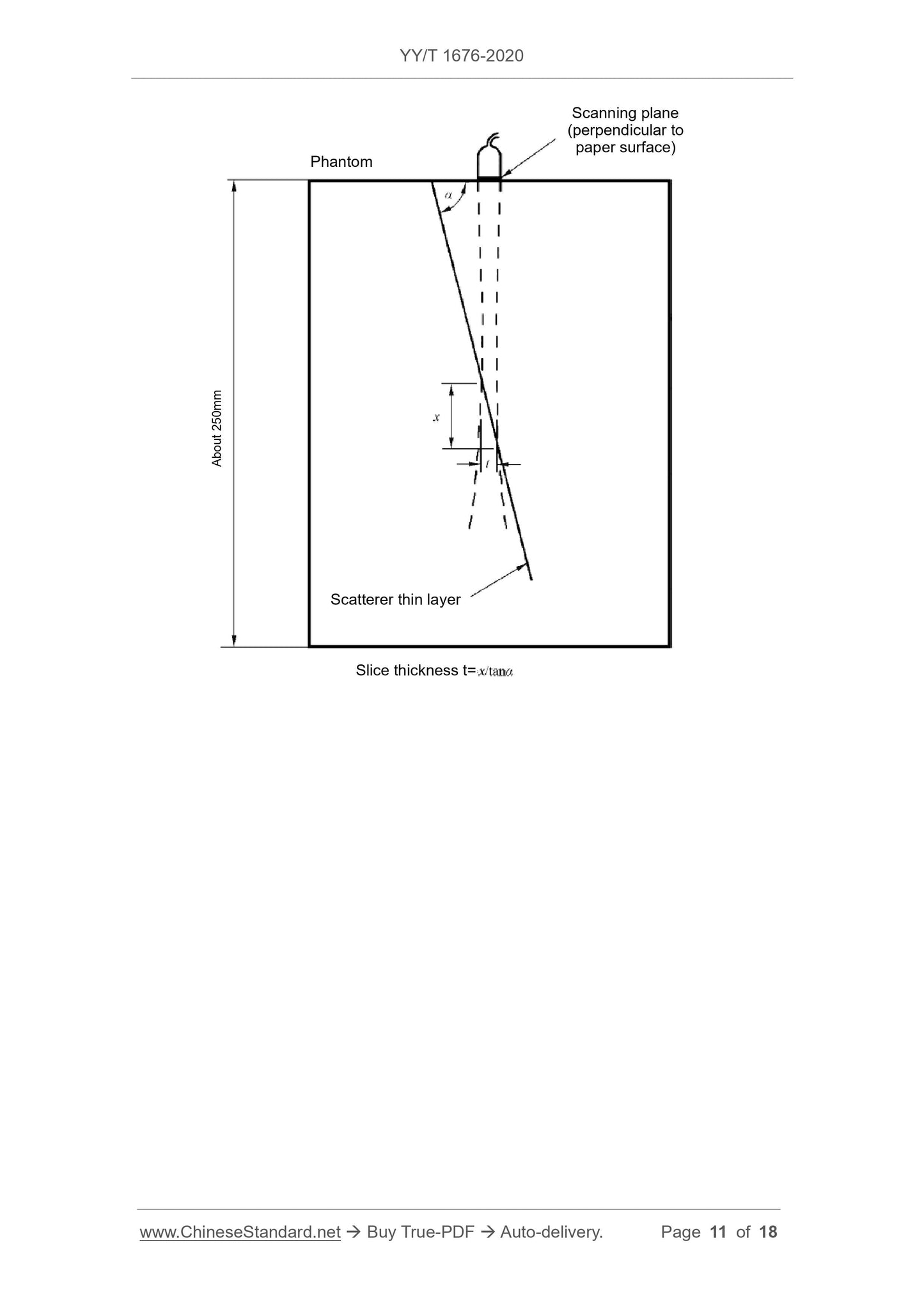
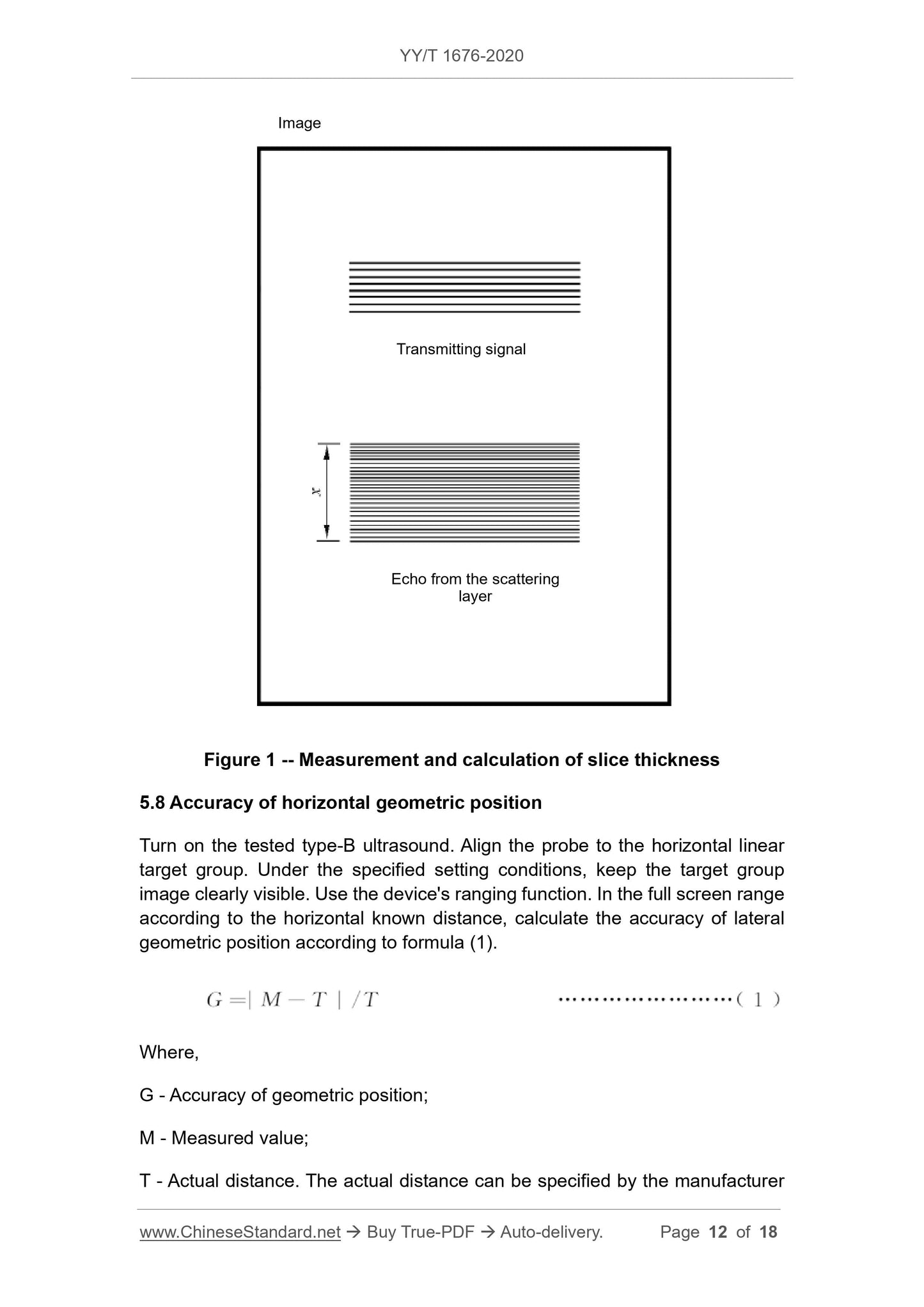
5.7 Slice thickness
Turn on the device under test, aim the probe at the thin layer of the scattering target, the scanning plane is perpendicular to the acoustic window of the ultrasound phantom, and the scanning plane intersects the acoustic window of the phantom.
The lines are parallel to the thin layer of scattering target. Under the specified setting conditions, adjust the intersection of the scanning plane and the scattering target thin layer to position it at a specific depth,
The thickness of the thin layer imaging of the scattering target is measured with an electronic cursor, and the slice thickness t at this depth is calculated.
For the equipped probe, if its detection depth is d, the slice thickness is measured at approximately d/3, d/2, and 2d/3.
The maximum value of the thin slice thickness of the scattering target at a specific depth is taken as the slice thickness of the probe, as shown in Figure 1.
Figure 1 Measurement and calculation of slice thickness
5.8 Horizontal geometric position accuracy
Turn on the tested B-ultrasound, aim the probe at the horizontal linear target group, and keep the target group image clearly visible under the specified setting conditions.
Equipped with a distance measuring function, the lateral geometric position accuracy is calculated according to equation (1) according to the known lateral distance within the full screen range.
5.9 Longitudinal geometric position accuracy
Turn on the tested B-ultrasound, aim the probe at the longitudinal linear target group, and keep the target group image clearly visible under the specified setting conditions.
Equipped with the distance measurement function, the axial geometric position accuracy is calculated according to the equation (1) according to the longitudinal known distance in the full screen range.
The longitudinal geometric position accuracy is usually expressed as a percentage.
5.10 Circumference and area measurement deviation
Turn on the device under test, scan the horizontal and vertical linear target group with the probe, and keep the target group image clearly visible under the specified setting conditions.
Maintain the center of the target group in the center of the field of view, and draw a closed figure (rectangular shape) in an area approximately equal to 75% of the field of view in the center of the display.
Shape or circle), measure the circumference and area, and calculate the error according to formula (1).
5.11 M mode performance indicators
The performance test of the equipment in M mode is carried out in accordance with the provisions of YY/T 0108.
5.12 3D imaging performance
The three-dimensional imaging performance test method shall be implemented in accordance with YY/T 1279.
5.13 Geometric position accuracy in the withdrawal direction
Turn on the device under test and measure two target lines with known distances at the middle of the withdrawal area specified by the manufacturer. In prescribed settings
Under the conditions, keep the target line image clearly visible, use the distance measuring function of the equipment to measure, and then calculate the geometric position accuracy of the withdrawal direction according to formula (1).
The geometric position accuracy of the withdrawal direction is usually expressed as a percentage.
During the test, the withdrawal speed of the ultrasonic transducer assembly should be recorded.
5.14 Geometric distortion of...
Get Quotation: Click YY/T 1676-2020 (Self-service in 1-minute)
Historical versions (Master-website): YY/T 1676-2020
Preview True-PDF (Reload/Scroll-down if blank)
YY/T 1676-2020: Ultrasound endoscope
YY/T 1676-2020
Ultrasound endoscope
ICS 11.040.55
C41
People's Republic of China Pharmaceutical Industry Standard
Ultrasound endoscope
2020-03-31 released
2022-10-01 implementation
Issued by the State Drug Administration
Table of contents
Preface Ⅲ
Introduction Ⅳ
1 Scope 1
2 Normative references 1
3 Terms and definitions 1
4 Requirements 2
5 Test method 3
Appendix A (informative appendix) Technical requirements for phantom and/or test piece 8
Preface
This standard was drafted in accordance with the rules given in GB/T 1.1-2009.
Please note that certain contents of this document may involve patents. The issuing agency of this document is not responsible for identifying these patents.
This standard was proposed by the State Drug Administration.
This standard is under the jurisdiction of the National Medical Electrical Appliance Standardization Technical Committee Medical Ultrasonic Equipment Subcommittee (SAC/TC10/SC2).
Drafting organizations of this standard. Hubei Provincial Medical Device Quality Supervision and Inspection Institute, Shenzhen Kaili Biomedical Technology Co., Ltd., North
Jinghua Kechuangzhi Health Technology Co., Ltd., Olympus (Beijing) Sales Service Co., Ltd. Shanghai Branch.
The main drafters of this standard. Xuanyuan Kai, Jiang Shilin, Wang Zhijian, Huang Tao, Chen Xiong, Zhou Zhifeng, Li Xiang, Chen Huahua.
introduction
Ultrasound endoscope installs a miniature ultrasound probe on the top of the endoscope to visually observe the external morphology of the lesion in the body cavity.
At the same time, real-time ultrasound imaging is performed on the cavity wall tissue to obtain the histological characteristic information of each level structure of the target tissue.
Ultrasound endoscope contains more technical content, this standard only involves the ultrasonic structure and function part.
Ultrasound endoscope
1 Scope
This standard specifies the terms and definitions, requirements and test methods of ultrasonic endoscopes related to ultrasonic performance.
This standard applies to ultrasound endoscopes and ultrasound probes that extend into the body through the endoscope tube.
Note. There are many types of ultrasound transducers for the current ultrasound endoscopes and ultrasound probes, such as single element rotation, circular array and convex array. This standard does not consider probes
The appearance and structure form of, the test method of the parameters takes single-element rotation, ring array and convex array imaging as examples. If necessary, more complex designs are also available
Use the basic methods described in this standard.
2 Normative references
The following documents are indispensable for the application of this document. For dated reference documents, only the dated version applies to this article
Pieces. For undated references, the latest version (including all amendments) applies to this document.
GB 9706.1 Medical Electrical Equipment Part 1.General Requirements for Safety
GB 9706.9 Medical electrical equipment Part 2-37.Special requirements for the safety of ultrasonic diagnostic and monitoring equipment
GB 10152 Type B ultrasonic diagnostic equipment
GB/T 14710 Environmental requirements and test methods for medical electrical appliances
YY/T 0108 M mode test method for ultrasonic diagnostic equipment
YY 0767 Ultrasonic color blood flow imaging system
YY/T 1279 Three-dimensional ultrasonic imaging performance test method
YY/T 1420 Environmental requirements and test methods for medical ultrasonic equipment
3 Terms and definitions
The following terms and definitions defined in GB 10152 apply to this document.
3.1
The ultrasound probe is located at the front end of the endoscope, which can not only realize the optical observation of the inner wall of the cavity, but also have the ability to supervise the inside of the target tissue.
Acoustic imaging function instrument.
3.2
Ultrasonic imaging geometric distortion The deviation of the ultrasonic image from the actual geometric structure of the test target.
3.3
Retracement direction
The direction in which the transducer is retracted radially.
3.4
Ultrasound viewing angle
The fan angle of the ultrasound image displayed on the screen.
4 requirements
4.1 Acoustic operating frequency
The deviation between the acoustic working frequency and the nominal acoustic working frequency should be within ±15%.
4.2 Detection depth
The detection depth shall meet the requirements announced by the manufacturer in the accompanying documents.
4.3 Lateral resolution
The lateral resolution shall meet the requirements announced by the manufacturer in the accompanying documents.
4.4 Axial resolution
The axial resolution shall meet the requirements announced by the manufacturer in the accompanying documents.
4.5 Dead zone
The blind zone shall meet the requirements announced by the manufacturer in the accompanying documents.
4.6 Slice thickness
If applicable, the slice thickness should meet the manufacturer's requirements published in the accompanying documents.
4.7 Horizontal geometric position accuracy
For the single-array element rotating probe, the accuracy of the lateral geometric position should be ≤10%;
For ring array probes and convex array probes, the horizontal geometric position accuracy should be ≤5%.
4.8 Longitudinal geometric position accuracy
For single-element rotating probes, the longitudinal geometric position accuracy should be ≤10%;
For ring array probes and convex array probes, the longitudinal geometric position accuracy should be ≤5%.
4.9 Circumference and area measurement deviation
If applicable, the perimeter and area measurement deviation should be within ±20%, or meet the manufacturer's requirements announced in the accompanying documents.
4.10 M mode performance indicators
For B-mode ultrasound probes with M mode, the performance indicators of M mode should meet the manufacturer's requirements published in the accompanying documents.
4.11 3D imaging performance
For equipment with 3D imaging function, its 3D imaging performance index (if applicable) should meet the requirements specified in YY/T 1279.
4.12 Geometric position accuracy in the withdrawal direction
If applicable, the geometric position accuracy of the withdrawal direction should meet the requirements announced by the manufacturer.
4.13 Geometric distortion of ultrasound imaging
The equipment images a target with a known geometric structure, and the deviation (percentage) between the measurement result of the geometric size and the actual size of the target should match
Meet the requirements announced by the manufacturer.
4.14 Ultrasonic color blood flow imaging performance
The performance of a system with color blood flow imaging function should meet the requirements of YY 0767.
4.15 Ultrasound viewing angle
If applicable, the ultrasound viewing angle should meet the requirements announced by the manufacturer.
4.16 Safety requirements
It shall meet the applicable requirements in GB 9706.1 and GB 9706.9.
4.17 Environmental test requirements
When the ultrasonic endoscope is undergoing environmental tests, see 4.2 for the inspection items of its ultrasonic performance part.
5 Test method
5.1 Overview
5.1.1 During the test, the working state of the equipment is set according to the conditions provided by the manufacturer, and the working state and test conditions should be accompanied by the test results
Announced.
5.1.2 In this standard, refer to Appendix A for the phantom and (or) test piece used in the test.
5.1.3 The test report should publish a schematic diagram of the phantom and (or) the target line of the test piece used for the measurement, including the structure, nominal distance, etc.
5.2 Acoustic operating frequency
The measurement of the acoustic working frequency should use a hydrophone to receive the ultrasonic frequency emitted by the ultrasonic transducer assembly; the echo method can also be used, even if
Align the reflective target with the ultrasonic transducer assembly, receive its reflected signal, and measure its frequency.
5.3 Detection depth
Turn on the device under test, aim the probe at the longitudinal depth target group, under the specified setting conditions, keep the target line image clearly visible, and move the probe
Head, observe the target line where the image can be distinguished farthest from the probe surface. The distance between the target line and the probe surface is the probe's detection
depth.
5.4 Lateral resolution
Turn on the device under test, aim the probe at the lateral resolution target group at a specific depth, and keep the target line image clear under the specified setting conditions.
It can be clearly seen that the micro-motion probe can be displayed as the minimum distance between the two target lines of the two echo signals, which is the lateral resolution at that depth.
For different nominal detection depths, it is recommended to measure the lateral resolution according to the following depth positions.
a) Nominal detection depth ≥ 3cm, specified by the manufacturer, measured at two positions within 1/2 and outside 1/2 of the nominal detection depth,
Take odd centimeters;
b) 1cm≤nominal detection depth < 3cm, only measure the lateral resolution at the detection depth of 1cm;
c) Nominal detection depth < 1cm, a measurement position specified by the manufacturer.
5.5 Axial resolution
Turn on the device under test, aim the probe at the axial resolution target group at a specific depth, and keep the target line image clear under the specified setting conditions.
It can be clearly seen that the micro-motion probe can be displayed as the minimum distance between the two target lines of the two echo signals, which is the axial resolution at that depth.
For different nominal detection depths, it is recommended to measure the axial resolution according to the following depth positions.
a) The nominal detection depth is ≥3cm, measured outside the lateral resolution measurement position;
b) 1cm≤nominal detection depth< 3cm, only measure the axial resolution at the detection depth< 2cm;
c) Nominal detection depth < 1cm, a measurement position specified by the manufacturer.
5.6 Dead zone
Turn on the device under test, align the probe to the target group in the blind zone, and keep the target line image clearly visible under the specified setting conditions.
Observe the target line closest to the probe surface and the subsequent image can be resolved. The distance between the target line and the probe surface is the blind zone of the probe.
Manufacturers can use other blind spot test methods (such as round hole method, see Appendix A.4) according to their own machine or probe characteristics, and provide test
Technical requirements of the test piece or phantom used in the test.
5.7 Slice thickness
Turn on the device under test, aim the probe at the thin layer of the scattering target, the scanning plane is perpendicular to the acoustic window of the ultrasound phantom, and the scanning plane intersects the acoustic window of the phantom.
The lines are parallel to the thin layer of scattering target. Under the specified setting conditions, adjust the intersection of the scanning plane and the scattering target thin layer to position it at a specific depth,
The thickness of the thin layer imaging of the scattering target is measured with an electronic cursor, and the slice thickness t at this depth is calculated.
For the equipped probe, if its detection depth is d, the slice thickness is measured at approximately d/3, d/2, and 2d/3.
The maximum value of the thin slice thickness of the scattering target at a specific depth is taken as the slice thickness of the probe, as shown in Figure 1.
Figure 1 Measurement and calculation of slice thickness
5.8 Horizontal geometric position accuracy
Turn on the tested B-ultrasound, aim the probe at the horizontal linear target group, and keep the target group image clearly visible under the specified setting conditions.
Equipped with a distance measuring function, the lateral geometric position accuracy is calculated according to equation (1) according to the known lateral distance within the full screen range.
5.9 Longitudinal geometric position accuracy
Turn on the tested B-ultrasound, aim the probe at the longitudinal linear target group, and keep the target group image clearly visible under the specified setting conditions.
Equipped with the distance measurement function, the axial geometric position accuracy is calculated according to the equation (1) according to the longitudinal known distance in the full screen range.
The longitudinal geometric position accuracy is usually expressed as a percentage.
5.10 Circumference and area measurement deviation
Turn on the device under test, scan the horizontal and vertical linear target group with the probe, and keep the target group image clearly visible under the specified setting conditions.
Maintain the center of the target group in the center of the field of view, and draw a closed figure (rectangular shape) in an area approximately equal to 75% of the field of view in the center of the display.
Shape or circle), measure the circumference and area, and calculate the error according to formula (1).
5.11 M mode performance indicators
The performance test of the equipment in M mode is carried out in accordance with the provisions of YY/T 0108.
5.12 3D imaging performance
The three-dimensional imaging performance test method shall be implemented in accordance with YY/T 1279.
5.13 Geometric position accuracy in the withdrawal direction
Turn on the device under test and measure two target lines with known distances at the middle of the withdrawal area specified by the manufacturer. In prescribed settings
Under the conditions, keep the target line image clearly visible, use the distance measuring function of the equipment to measure, and then calculate the geometric position accuracy of the withdrawal direction according to formula (1).
The geometric position accuracy of the withdrawal direction is usually expressed as a percentage.
During the test, the withdrawal speed of the ultrasonic transducer assembly should be recorded.
5.14 Geometric distortion of...
Share