


1
/
av
12
PayPal, credit cards. Download editable-PDF & invoice in 1 second!
QC/T 1124-2019 English PDF (QCT1124-2019)
QC/T 1124-2019 English PDF (QCT1124-2019)
Ordinarie pris
$310.00 USD
Ordinarie pris
Försäljningspris
$310.00 USD
Enhetspris
/
per
Frakt beräknas i kassan.
Det gick inte att ladda hämtningstillgänglighet
Delivery: 3 seconds. Download true-PDF + Invoice.
Get QUOTATION in 1-minute: Click QC/T 1124-2019
Historical versions: QC/T 1124-2019
Preview True-PDF (Reload/Scroll if blank)
QC/T 1124-2019: Endurance test method for adjuster of motor vehicle adaptive front lighting system
QC/T 1124-2019
QC
AUTOMOBILE INDUSTRY STANDARD
OF THE PEOPLE’S REPUBLIC OF CHINA
ICS 43.040.20
T 38
Endurance test method for adjuster of motor vehicle
adaptive front lighting system
ISSUED ON: NOVEMBER 11, 2019
IMPLEMENTED ON: APRIL 01, 2020
Issued by: Ministry of Industry and Information Technology of PRC
Table of Contents
Foreword ... 7
1 Scope ... 8
2 Normative references ... 8
3 Terms and definitions ... 8
4 Symbols, codes, abbreviations ... 10
5 General requirements ... 10
6 Test method ... 11
7 Evaluation indicators ... 15
Appendix A (Normative) Headlight operating mode ... 17
Appendix B (Normative) Main test loop in the test ... 18
Endurance test method for adjuster of motor vehicle
adaptive front lighting system
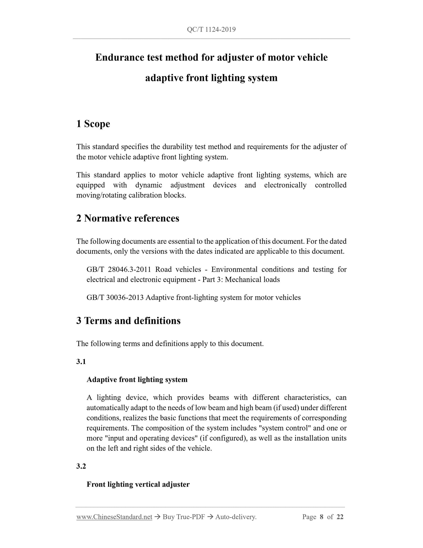
1 Scope
This standard specifies the durability test method and requirements for the adjuster of
the motor vehicle adaptive front lighting system.
This standard applies to motor vehicle adaptive front lighting systems, which are
equipped with dynamic adjustment devices and electronically controlled
moving/rotating calibration blocks.
2 Normative references
The following documents are essential to the application of this document. For the dated
documents, only the versions with the dates indicated are applicable to this document.
GB/T 28046.3-2011 Road vehicles - Environmental conditions and testing for
electrical and electronic equipment - Part 3: Mechanical loads
GB/T 30036-2013 Adaptive front-lighting system for motor vehicles
3 Terms and definitions
The following terms and definitions apply to this document.
3.1
Adaptive front lighting system
A lighting device, which provides beams with different characteristics, can
automatically adapt to the needs of low beam and high beam (if used) under different
conditions, realizes the basic functions that meet the requirements of corresponding
requirements. The composition of the system includes "system control" and one or
more "input and operating devices" (if configured), as well as the installation units
on the left and right sides of the vehicle.
3.2
Front lighting vertical adjuster
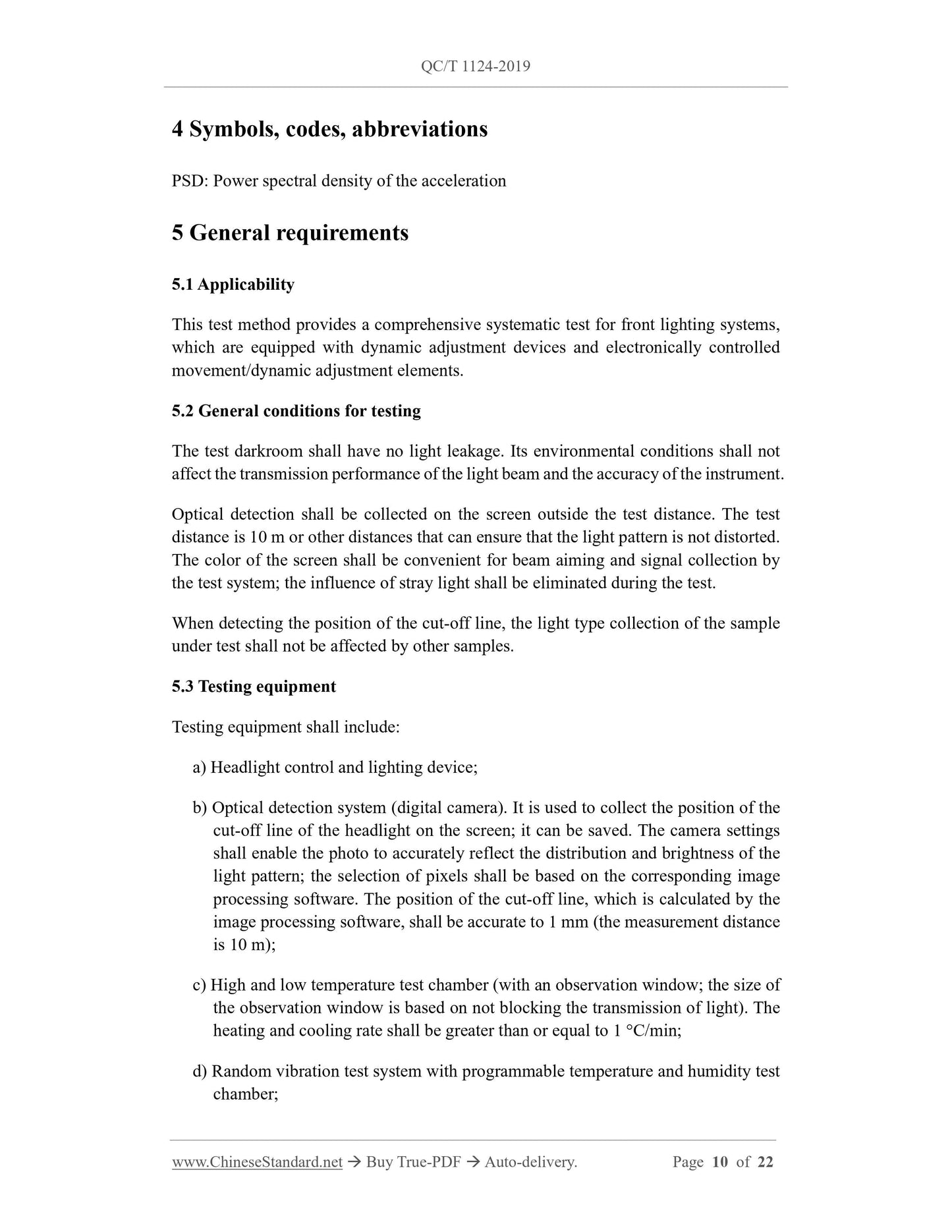
4 Symbols, codes, abbreviations
PSD: Power spectral density of the acceleration
5 General requirements
5.1 Applicability
This test method provides a comprehensive systematic test for front lighting systems,
which are equipped with dynamic adjustment devices and electronically controlled
movement/dynamic adjustment elements.
5.2 General conditions for testing
The test darkroom shall have no light leakage. Its environmental conditions shall not
affect the transmission performance of the light beam and the accuracy of the instrument.
Optical detection shall be collected on the screen outside the test distance. The test
distance is 10 m or other distances that can ensure that the light pattern is not distorted.
The color of the screen shall be convenient for beam aiming and signal collection by
the test system; the influence of stray light shall be eliminated during the test.
When detecting the position of the cut-off line, the light type collection of the sample
under test shall not be affected by other samples.
5.3 Testing equipment
Testing equipment shall include:
a) Headlight control and lighting device;
b) Optical detection system (digital camera). It is used to collect the position of the
cut-off line of the headlight on the screen; it can be saved. The camera settings
shall enable the photo to accurately reflect the distribution and brightness of the
light pattern; the selection of pixels shall be based on the corresponding image
processing software. The position of the cut-off line, which is calculated by the
image processing software, shall be accurate to 1 mm (the measurement distance
is 10 m);
c) High and low temperature test chamber (with an observation window; the size of
the observation window is based on not blocking the transmission of light). The
heating and cooling rate shall be greater than or equal to 1 °C/min;
d) Random vibration test system with programmable temperature and humidity test
chamber;
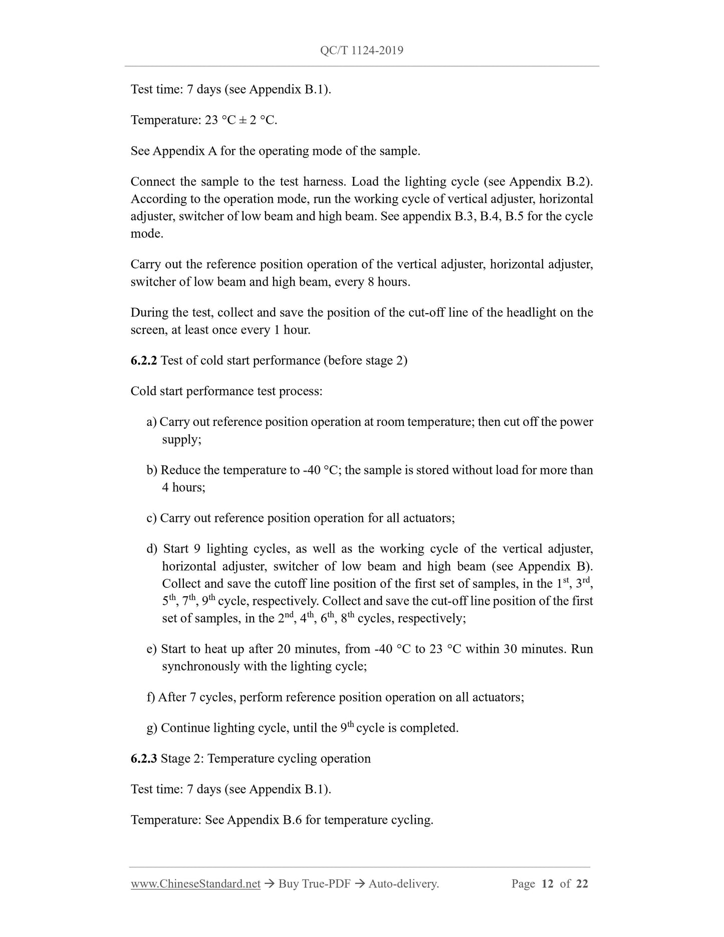
Test time: 7 days (see Appendix B.1).
Temperature: 23 °C ± 2 °C.
See Appendix A for the operating mode of the sample.
Connect the sample to the test harness. Load the lighting cycle (see Appendix B.2).
According to the operation mode, run the working cycle of vertical adjuster, horizontal
adjuster, switcher of low beam and high beam. See appendix B.3, B.4, B.5 for the cycle
mode.
Carry out the reference position operation of the vertical adjuster, horizontal adjuster,
switcher of low beam and high beam, every 8 hours.
During the test, collect and save the position of the cut-off line of the headlight on the
screen, at least once every 1 hour.
6.2.2 Test of cold start performance (before stage 2)
Cold start performance test process:
a) Carry out reference position operation at room temperature; then cut off the power
supply;
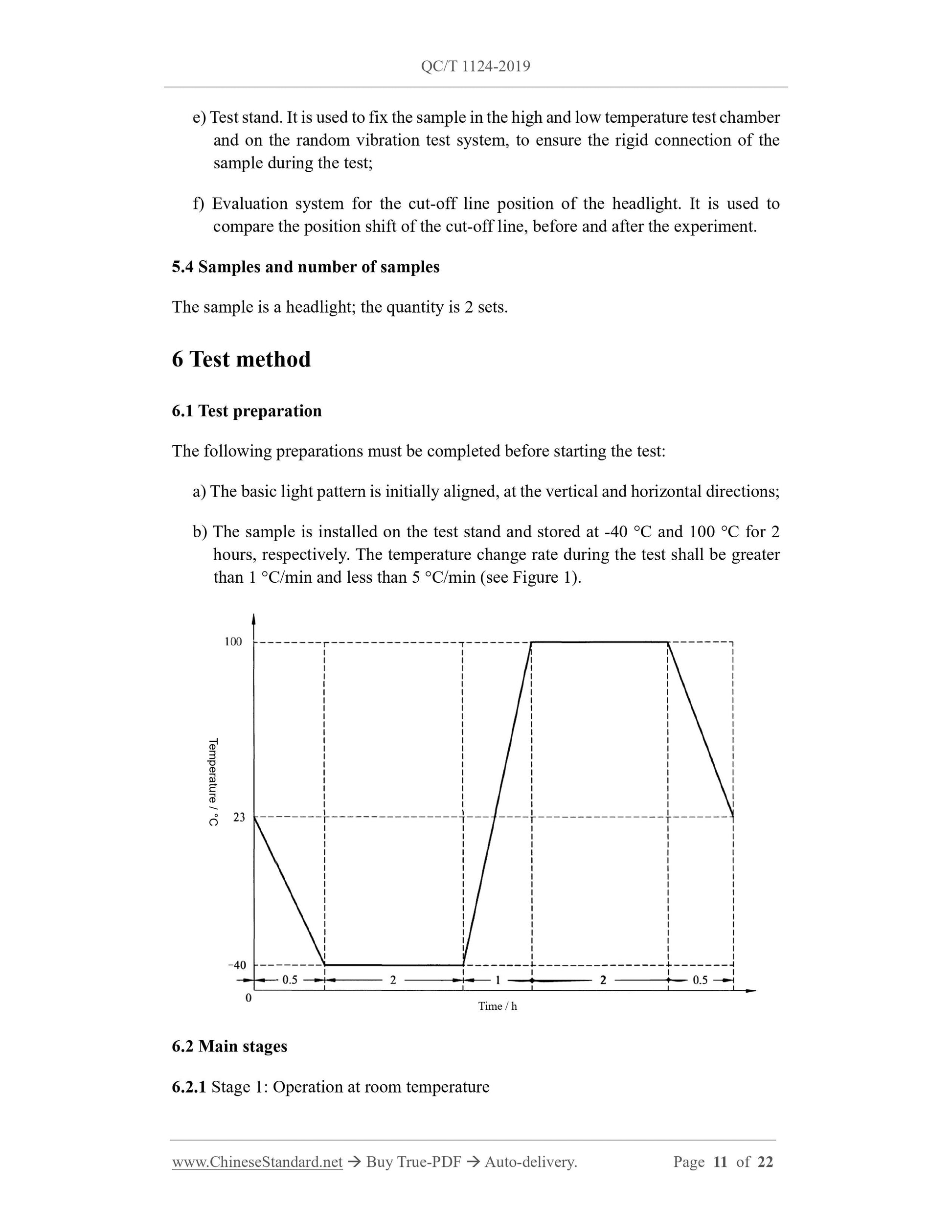
b) Reduce the temperature to -40 °C; the sample is stored without load for more than
4 hours;
c) Carry out reference position operation for all actuators;
d) Start 9 lighting cycles, as well as the working cycle of the vertical adjuster,
horizontal adjuster, switcher of low beam and high beam (see Appendix B).
Collect and save the cutoff line position of the first set of samples, in the 1st, 3rd,
5th, 7th, 9th cycle, respectively. Collect and save the cut-off line position of the first
set of samples, in the 2nd, 4th, 6th, 8th cycles, respectively;
e) Start to heat up after 20 minutes, from -40 °C to 23 °C within 30 minutes. Run
synchronously with the lighting cycle;
f) After 7 cycles, perform reference position operation on all actuators;
g) Continue lighting cycle, until the 9th cycle is completed.
6.2.3 Stage 2: Temperature cycling operation
Test time: 7 days (see Appendix B.1).
Temperature: See Appendix B.6 for temperature cycling.
See Appendix A for the operating mode of the sample.
Connect the sample to the test harness. Load the lighting cycle (see Appendix B.2).
According to the operation mode, run the working cycle of vertical adjuster, horizontal
adjuster, switcher of low beam and high beam. See appendix B.3, B.4, B.5 for the cycle
mode.
Carry out the reference position operation of the vertical adjuster, horizontal adjuster,
switcher of low beam and high beam, every 8 hours.
During the test, collect and save the position of the cut-off line of the headlight on the
screen, at least once every 1 hour.
6.2.4 Re-test of cold start performance (after stage 2)
Same as clause 6.2.2.
6.2.5 Stage 3: Operation at room temperature
Test duration: 7 days (see Appendix B.1).
Temperature: 23 °C ± 2 °C.
See Appendix A for the operating mode of the sample.
Connect the sample to the test harness. Load the lighting cycle (see Appendix B.2).
According to the operation mode, run the working cycle of vertical adjuster, horizontal
adjuster, switcher of low beam and high beam. See appendix B.3, B.4, B.5 for the cycle
mode.
Carry out the reference position operation of the vertical adjuster, horizontal adjuster,
switcher of low beam and high beam, every 10 min.
During the test, collect and save the position of the cut-off line of the headlight on the
screen, at least once every 1 hour.
6.2.6 Stage 4: Broadband noise vibration with temperature
Test duration: 3 days (see Appendix B.1).
Vibration direction: Vertical (see Appendix B.1). <...
Get QUOTATION in 1-minute: Click QC/T 1124-2019
Historical versions: QC/T 1124-2019
Preview True-PDF (Reload/Scroll if blank)
QC/T 1124-2019: Endurance test method for adjuster of motor vehicle adaptive front lighting system
QC/T 1124-2019
QC
AUTOMOBILE INDUSTRY STANDARD
OF THE PEOPLE’S REPUBLIC OF CHINA
ICS 43.040.20
T 38
Endurance test method for adjuster of motor vehicle
adaptive front lighting system
ISSUED ON: NOVEMBER 11, 2019
IMPLEMENTED ON: APRIL 01, 2020
Issued by: Ministry of Industry and Information Technology of PRC
Table of Contents
Foreword ... 7
1 Scope ... 8
2 Normative references ... 8
3 Terms and definitions ... 8
4 Symbols, codes, abbreviations ... 10
5 General requirements ... 10
6 Test method ... 11
7 Evaluation indicators ... 15
Appendix A (Normative) Headlight operating mode ... 17
Appendix B (Normative) Main test loop in the test ... 18
Endurance test method for adjuster of motor vehicle
adaptive front lighting system
1 Scope
This standard specifies the durability test method and requirements for the adjuster of
the motor vehicle adaptive front lighting system.
This standard applies to motor vehicle adaptive front lighting systems, which are
equipped with dynamic adjustment devices and electronically controlled
moving/rotating calibration blocks.
2 Normative references
The following documents are essential to the application of this document. For the dated
documents, only the versions with the dates indicated are applicable to this document.
GB/T 28046.3-2011 Road vehicles - Environmental conditions and testing for
electrical and electronic equipment - Part 3: Mechanical loads
GB/T 30036-2013 Adaptive front-lighting system for motor vehicles
3 Terms and definitions
The following terms and definitions apply to this document.
3.1
Adaptive front lighting system
A lighting device, which provides beams with different characteristics, can
automatically adapt to the needs of low beam and high beam (if used) under different
conditions, realizes the basic functions that meet the requirements of corresponding
requirements. The composition of the system includes "system control" and one or
more "input and operating devices" (if configured), as well as the installation units
on the left and right sides of the vehicle.
3.2
Front lighting vertical adjuster
4 Symbols, codes, abbreviations
PSD: Power spectral density of the acceleration
5 General requirements
5.1 Applicability
This test method provides a comprehensive systematic test for front lighting systems,
which are equipped with dynamic adjustment devices and electronically controlled
movement/dynamic adjustment elements.
5.2 General conditions for testing
The test darkroom shall have no light leakage. Its environmental conditions shall not
affect the transmission performance of the light beam and the accuracy of the instrument.
Optical detection shall be collected on the screen outside the test distance. The test
distance is 10 m or other distances that can ensure that the light pattern is not distorted.
The color of the screen shall be convenient for beam aiming and signal collection by
the test system; the influence of stray light shall be eliminated during the test.
When detecting the position of the cut-off line, the light type collection of the sample
under test shall not be affected by other samples.
5.3 Testing equipment
Testing equipment shall include:
a) Headlight control and lighting device;
b) Optical detection system (digital camera). It is used to collect the position of the
cut-off line of the headlight on the screen; it can be saved. The camera settings
shall enable the photo to accurately reflect the distribution and brightness of the
light pattern; the selection of pixels shall be based on the corresponding image
processing software. The position of the cut-off line, which is calculated by the
image processing software, shall be accurate to 1 mm (the measurement distance
is 10 m);
c) High and low temperature test chamber (with an observation window; the size of
the observation window is based on not blocking the transmission of light). The
heating and cooling rate shall be greater than or equal to 1 °C/min;
d) Random vibration test system with programmable temperature and humidity test
chamber;
Test time: 7 days (see Appendix B.1).
Temperature: 23 °C ± 2 °C.
See Appendix A for the operating mode of the sample.
Connect the sample to the test harness. Load the lighting cycle (see Appendix B.2).
According to the operation mode, run the working cycle of vertical adjuster, horizontal
adjuster, switcher of low beam and high beam. See appendix B.3, B.4, B.5 for the cycle
mode.
Carry out the reference position operation of the vertical adjuster, horizontal adjuster,
switcher of low beam and high beam, every 8 hours.
During the test, collect and save the position of the cut-off line of the headlight on the
screen, at least once every 1 hour.
6.2.2 Test of cold start performance (before stage 2)
Cold start performance test process:
a) Carry out reference position operation at room temperature; then cut off the power
supply;
b) Reduce the temperature to -40 °C; the sample is stored without load for more than
4 hours;
c) Carry out reference position operation for all actuators;
d) Start 9 lighting cycles, as well as the working cycle of the vertical adjuster,
horizontal adjuster, switcher of low beam and high beam (see Appendix B).
Collect and save the cutoff line position of the first set of samples, in the 1st, 3rd,
5th, 7th, 9th cycle, respectively. Collect and save the cut-off line position of the first
set of samples, in the 2nd, 4th, 6th, 8th cycles, respectively;
e) Start to heat up after 20 minutes, from -40 °C to 23 °C within 30 minutes. Run
synchronously with the lighting cycle;
f) After 7 cycles, perform reference position operation on all actuators;
g) Continue lighting cycle, until the 9th cycle is completed.
6.2.3 Stage 2: Temperature cycling operation
Test time: 7 days (see Appendix B.1).
Temperature: See Appendix B.6 for temperature cycling.
See Appendix A for the operating mode of the sample.
Connect the sample to the test harness. Load the lighting cycle (see Appendix B.2).
According to the operation mode, run the working cycle of vertical adjuster, horizontal
adjuster, switcher of low beam and high beam. See appendix B.3, B.4, B.5 for the cycle
mode.
Carry out the reference position operation of the vertical adjuster, horizontal adjuster,
switcher of low beam and high beam, every 8 hours.
During the test, collect and save the position of the cut-off line of the headlight on the
screen, at least once every 1 hour.
6.2.4 Re-test of cold start performance (after stage 2)
Same as clause 6.2.2.
6.2.5 Stage 3: Operation at room temperature
Test duration: 7 days (see Appendix B.1).
Temperature: 23 °C ± 2 °C.
See Appendix A for the operating mode of the sample.
Connect the sample to the test harness. Load the lighting cycle (see Appendix B.2).
According to the operation mode, run the working cycle of vertical adjuster, horizontal
adjuster, switcher of low beam and high beam. See appendix B.3, B.4, B.5 for the cycle
mode.
Carry out the reference position operation of the vertical adjuster, horizontal adjuster,
switcher of low beam and high beam, every 10 min.
During the test, collect and save the position of the cut-off line of the headlight on the
screen, at least once every 1 hour.
6.2.6 Stage 4: Broadband noise vibration with temperature
Test duration: 3 days (see Appendix B.1).
Vibration direction: Vertical (see Appendix B.1). <...
Share