1
/
av
12
PayPal, credit cards. Download editable-PDF & invoice in 1 second!
QC/T 1175-2022 English PDF (QCT1175-2022)
QC/T 1175-2022 English PDF (QCT1175-2022)
Ordinarie pris
$455.00 USD
Ordinarie pris
Försäljningspris
$455.00 USD
Enhetspris
/
per
Frakt beräknas i kassan.
Det gick inte att ladda hämtningstillgänglighet
Delivery: 3 seconds. Download true-PDF + Invoice.
Get QUOTATION in 1-minute: Click QC/T 1175-2022
Historical versions: QC/T 1175-2022
Preview True-PDF (Reload/Scroll if blank)
QC/T 1175-2022: High voltage contactor for electric vehicles
QC/T 1175-2022
QC
AUTOMOBILE INDUSTRY STANDARD
OF THE PEOPLE’S REPUBLIC OF CHINA
ICS 43.020
CCS T 09
High voltage contactor for electric vehicles
ISSUED ON: APRIL 08, 2022
IMPLEMENTED ON: OCTOBER 01, 2022
Issued by: Ministry of Industry and Information Technology of PRC
Table of Contents
Foreword ... 6
1 Scope ... 7
2 Normative references ... 7
3 Terms and definitions ... 8
4 Symbols and abbreviations ... 10
5 Requirements ... 10
6 Test method ... 16
7 Inspection rules ... 35
Appendix A (Informative) Contactor classification ... 38
Appendix B (Informative) Guidelines for the use of contactors ... 39
References ... 41
High voltage contactor for electric vehicles
1 Scope
This document specifies the technical requirements, test methods, inspection rules for
high-voltage contactors for electric vehicles.
This document applies to high-voltage contactors for electric vehicles (hereinafter
referred to as contactors), which has a rated DC operating voltage of the main contacts
in the range of 60 V ~ 1500 V.
This document does not apply to AC contactors for electric vehicles.
2 Normative references
The contents of the following documents constitute the essential provisions of this
document through normative references in the text. Among them, for dated references,
only the version corresponding to the date is applicable to this document; for undated
references, the latest version (including all amendments) is applicable to this document.
GB/T 2423.56-2018 Environmental testing - Part 2: Test methods - Test Fh:
Vibration, broadband random and guidance
GB/T 2423.18-2012 Environmental testing - Part 2: Test methods - Test Kb: Salt
mist, cyclic (sodium chloride solution)
GB/T 2423.34-2012 Environmental testing - Part 2: Test methods - Test Z/AD:
Composite temperature/humidity cyclic test
GB/T 2900.18-2008 Electrotechnical terminology - Low voltage apparatus
GB/T 5169.11-2017 Fire hazard testing for electric and electronic products - Part 11:
Glowing/hot-wire based test methods - Glow-wire flammability test method for end-
products (GWEPT)
GB/T 14048.1-2012 Low-voltage switchgear and controlgear - Part 1: General
principles
GB/T 17626.4-2018 Electromagnetic compatibility - Testing and measurement
techniques - Electrical fast transient/burst immunity test
GB/T 18655-2018 Vehicles, boats and internal combustion engines - Radio
disturbance characteristics - Limits and methods of measurement for the protection
of on-board receivers
GB/T 19951 Road vehicles - Disturbances test methods for electrical/electronic
component from electrostatic discharge
GB/T 21437.2-2008 Road vehicles - Electrical disturbances from conduction and
coupling - Part 2: Electrical transient conduction along supply lines only
GB/T 28046.3-2011 Road vehicles - Environmental conditions and testing for
electrical and electronic equipment - Part 3: Mechanical loads
GB/T 33014.2-2016 Road vehicles - Component test methods for
electrical/electronic disturbances from narrowband radiated electromagnetic energy
- Part 2: Absorb-lined shielded enclosure
GB/T 33014.4-2016 Road vehicles - Component test methods for
electrical/electronic disturbances from narrowband radiated electromagnetic energy
- Part 4: Bulk current injection (BCI)
ISO 11452-8:2015 Road vehicles - Component test methods for electrical
disturbances from narrowband radiated electromagnetic energy - Part 8: Immunity
to magnetic field
3 Terms and definitions
The terms and definitions as defined in GB/T 2900.18-2008 and GB/T 14048.1-2012,
as well as the following terms and definitions, apply to this document.
3.1
Contactor
A non-manually operated mechanical switching device, that has only one rest
position and can make, carry and break current, under normal circuit conditions
(including overload operating conditions).
3.2
Contact resistance
The resistance value between the closed contacts, which are measured from the two
terminals of the contact assembly.
3.3
Contact rated voltage
a) Operation mode 1: The contactor coil's end connector is normally connected, BUT
no power is supplied;
b) Operation mode 2: The coil end of the contactor supplies power, BUT the contact
does not supply power;
c) Operation mode 3: The coil end of the contactor supplies power, AND the contacts
supply power.
Note: Contact power supply generally means that the contactor's contacts pass a constant
rated current, without requirements for the voltage. If there are special circumstances, the
contact power supply situation can be determined, through negotiation, between the supplier
and the buyer. The coil power supply refers to the supply of test voltage to the contactor
coil's control circuit.
4 Symbols and abbreviations
The following symbols and abbreviations apply to this document.
RT - Room temperature;
Tmax - Maximum operating temperature;
Tmin - Minimum operating temperature;
UN - Rated voltage;
Usmin - Minimum operating voltage;
tA - Glow wire application time;
tE - Duration from application of the tip of the glow-wire to the start of the test until
all flames are extinguished;
ΔT - Temperature difference.
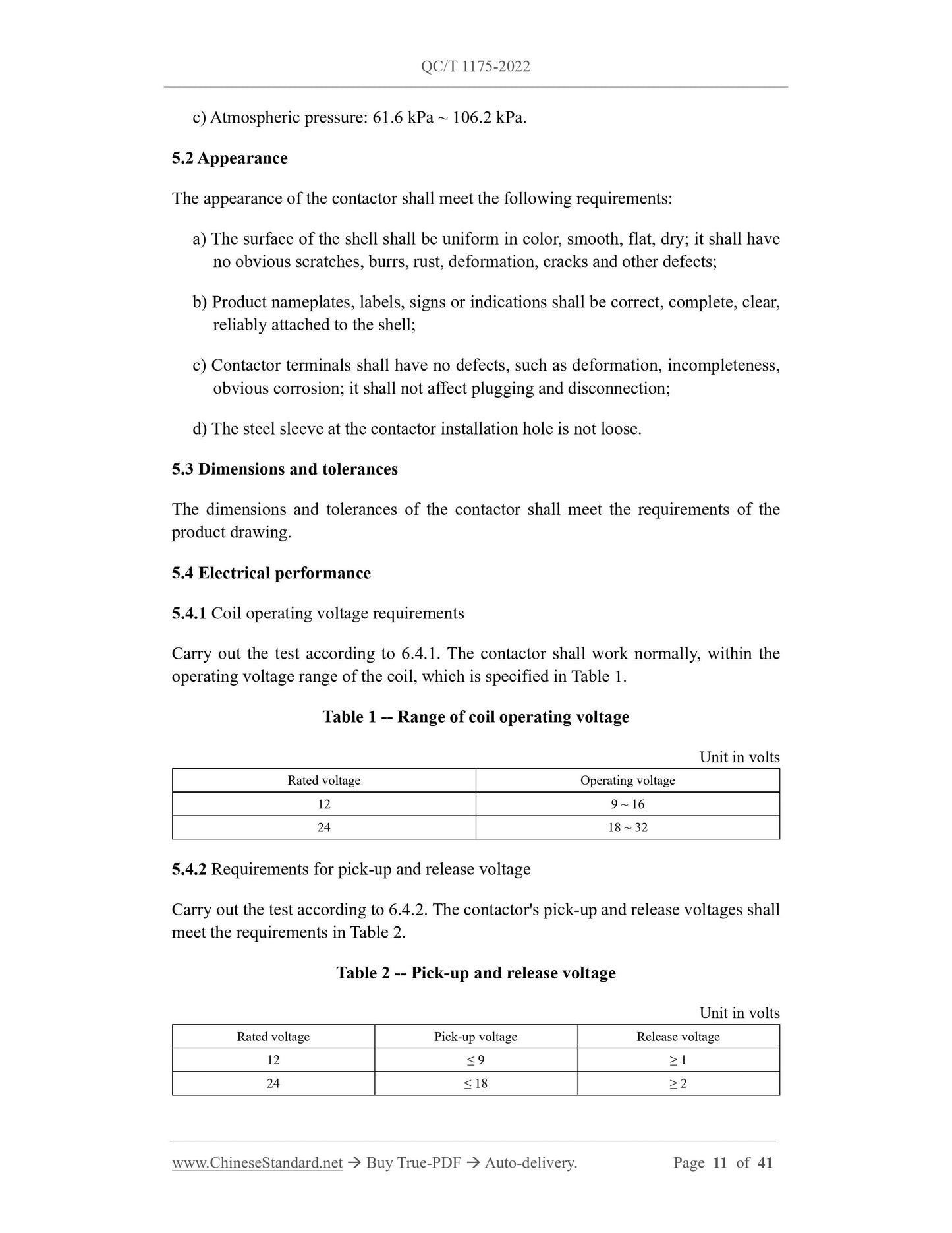
5 Requirements
5.1 Working environment
Unless otherwise specified, the contactor shall work normally under the following
environmental conditions:
a) Working environment temperature: -40 °C ~ 85 °C;
b) Relative humidity: 5% ~ 95%;
5.4.3 Requirements for make time and release time
Carry out the test according to 6.4.3. The make time of the contactor shall be less than
50 ms; the release time shall be less than 30 ms.
5.4.4 Coil short-term overvoltage requirements
Carry out the test according to 6.4.4. During the test, the contactor shall work normally.
After the test, the contactor shall meet the requirements of 5.4.2, 5.4.3, 5.4.8, 5.4.9,
5.4.10.
5.4.5 Coil long-term overvoltage requirements
Carry out the test according to 6.4.5. During the test, the contactor shall work normally.
After the test, the contactor shall meet the requirements of 5.4.2, 5.4.3, 5.4.8, 5.4.9,
5.4.10.
5.4.6 Voltage drop requirements
Carry out the test according to 6.4.6. Within the operating voltage range of the coil, the
contactor shall work normally. Outside the operating voltage range of the coil, the
contactor can be disconnected. After the test, the contactor shall meet the requirements
of 5.4.2, 5.4.3, 5.4.8, 5.4.9, 5.4.10.
5.4.7 Coil reverse voltage requirements
Carry out the test according to 6.4.7. The contactor shall meet the following
requirements:
a) Contactor with circuit board: When a reverse voltage is applied to the coil end,
the circuit board of the contactor shall not be damaged. When the forward test
voltage is applied after the test, the contactor shall comply with the requirements
of 5.4.2, 5.4.3, 5.4.8, 5.4.9, 5.4.10;
b) Contactor without circuit board: The contactor shall work normally during the test.
The contactor shall comply with the requirements of 5.4.2, 5.4.3, 5.4.8, 5.4.9,
5.4.10.
5.4.8 Requirements for contact voltage drop/contact resistance
Carry out the test in accordance with 6.4.8. The contact voltage drop/contact resistance
of the contactor, before and after the test, shall meet the values, which are negotiated
and determined between the supplier and the purchaser.
5.4.9 Requirements for insulation resistance
Carry out the test according to 6.4.9. Before the test, ...
Get QUOTATION in 1-minute: Click QC/T 1175-2022
Historical versions: QC/T 1175-2022
Preview True-PDF (Reload/Scroll if blank)
QC/T 1175-2022: High voltage contactor for electric vehicles
QC/T 1175-2022
QC
AUTOMOBILE INDUSTRY STANDARD
OF THE PEOPLE’S REPUBLIC OF CHINA
ICS 43.020
CCS T 09
High voltage contactor for electric vehicles
ISSUED ON: APRIL 08, 2022
IMPLEMENTED ON: OCTOBER 01, 2022
Issued by: Ministry of Industry and Information Technology of PRC
Table of Contents
Foreword ... 6
1 Scope ... 7
2 Normative references ... 7
3 Terms and definitions ... 8
4 Symbols and abbreviations ... 10
5 Requirements ... 10
6 Test method ... 16
7 Inspection rules ... 35
Appendix A (Informative) Contactor classification ... 38
Appendix B (Informative) Guidelines for the use of contactors ... 39
References ... 41
High voltage contactor for electric vehicles
1 Scope
This document specifies the technical requirements, test methods, inspection rules for
high-voltage contactors for electric vehicles.
This document applies to high-voltage contactors for electric vehicles (hereinafter
referred to as contactors), which has a rated DC operating voltage of the main contacts
in the range of 60 V ~ 1500 V.
This document does not apply to AC contactors for electric vehicles.
2 Normative references
The contents of the following documents constitute the essential provisions of this
document through normative references in the text. Among them, for dated references,
only the version corresponding to the date is applicable to this document; for undated
references, the latest version (including all amendments) is applicable to this document.
GB/T 2423.56-2018 Environmental testing - Part 2: Test methods - Test Fh:
Vibration, broadband random and guidance
GB/T 2423.18-2012 Environmental testing - Part 2: Test methods - Test Kb: Salt
mist, cyclic (sodium chloride solution)
GB/T 2423.34-2012 Environmental testing - Part 2: Test methods - Test Z/AD:
Composite temperature/humidity cyclic test
GB/T 2900.18-2008 Electrotechnical terminology - Low voltage apparatus
GB/T 5169.11-2017 Fire hazard testing for electric and electronic products - Part 11:
Glowing/hot-wire based test methods - Glow-wire flammability test method for end-
products (GWEPT)
GB/T 14048.1-2012 Low-voltage switchgear and controlgear - Part 1: General
principles
GB/T 17626.4-2018 Electromagnetic compatibility - Testing and measurement
techniques - Electrical fast transient/burst immunity test
GB/T 18655-2018 Vehicles, boats and internal combustion engines - Radio
disturbance characteristics - Limits and methods of measurement for the protection
of on-board receivers
GB/T 19951 Road vehicles - Disturbances test methods for electrical/electronic
component from electrostatic discharge
GB/T 21437.2-2008 Road vehicles - Electrical disturbances from conduction and
coupling - Part 2: Electrical transient conduction along supply lines only
GB/T 28046.3-2011 Road vehicles - Environmental conditions and testing for
electrical and electronic equipment - Part 3: Mechanical loads
GB/T 33014.2-2016 Road vehicles - Component test methods for
electrical/electronic disturbances from narrowband radiated electromagnetic energy
- Part 2: Absorb-lined shielded enclosure
GB/T 33014.4-2016 Road vehicles - Component test methods for
electrical/electronic disturbances from narrowband radiated electromagnetic energy
- Part 4: Bulk current injection (BCI)
ISO 11452-8:2015 Road vehicles - Component test methods for electrical
disturbances from narrowband radiated electromagnetic energy - Part 8: Immunity
to magnetic field
3 Terms and definitions
The terms and definitions as defined in GB/T 2900.18-2008 and GB/T 14048.1-2012,
as well as the following terms and definitions, apply to this document.
3.1
Contactor
A non-manually operated mechanical switching device, that has only one rest
position and can make, carry and break current, under normal circuit conditions
(including overload operating conditions).
3.2
Contact resistance
The resistance value between the closed contacts, which are measured from the two
terminals of the contact assembly.
3.3
Contact rated voltage
a) Operation mode 1: The contactor coil's end connector is normally connected, BUT
no power is supplied;
b) Operation mode 2: The coil end of the contactor supplies power, BUT the contact
does not supply power;
c) Operation mode 3: The coil end of the contactor supplies power, AND the contacts
supply power.
Note: Contact power supply generally means that the contactor's contacts pass a constant
rated current, without requirements for the voltage. If there are special circumstances, the
contact power supply situation can be determined, through negotiation, between the supplier
and the buyer. The coil power supply refers to the supply of test voltage to the contactor
coil's control circuit.
4 Symbols and abbreviations
The following symbols and abbreviations apply to this document.
RT - Room temperature;
Tmax - Maximum operating temperature;
Tmin - Minimum operating temperature;
UN - Rated voltage;
Usmin - Minimum operating voltage;
tA - Glow wire application time;
tE - Duration from application of the tip of the glow-wire to the start of the test until
all flames are extinguished;
ΔT - Temperature difference.
5 Requirements
5.1 Working environment
Unless otherwise specified, the contactor shall work normally under the following
environmental conditions:
a) Working environment temperature: -40 °C ~ 85 °C;
b) Relative humidity: 5% ~ 95%;
5.4.3 Requirements for make time and release time
Carry out the test according to 6.4.3. The make time of the contactor shall be less than
50 ms; the release time shall be less than 30 ms.
5.4.4 Coil short-term overvoltage requirements
Carry out the test according to 6.4.4. During the test, the contactor shall work normally.
After the test, the contactor shall meet the requirements of 5.4.2, 5.4.3, 5.4.8, 5.4.9,
5.4.10.
5.4.5 Coil long-term overvoltage requirements
Carry out the test according to 6.4.5. During the test, the contactor shall work normally.
After the test, the contactor shall meet the requirements of 5.4.2, 5.4.3, 5.4.8, 5.4.9,
5.4.10.
5.4.6 Voltage drop requirements
Carry out the test according to 6.4.6. Within the operating voltage range of the coil, the
contactor shall work normally. Outside the operating voltage range of the coil, the
contactor can be disconnected. After the test, the contactor shall meet the requirements
of 5.4.2, 5.4.3, 5.4.8, 5.4.9, 5.4.10.
5.4.7 Coil reverse voltage requirements
Carry out the test according to 6.4.7. The contactor shall meet the following
requirements:
a) Contactor with circuit board: When a reverse voltage is applied to the coil end,
the circuit board of the contactor shall not be damaged. When the forward test
voltage is applied after the test, the contactor shall comply with the requirements
of 5.4.2, 5.4.3, 5.4.8, 5.4.9, 5.4.10;
b) Contactor without circuit board: The contactor shall work normally during the test.
The contactor shall comply with the requirements of 5.4.2, 5.4.3, 5.4.8, 5.4.9,
5.4.10.
5.4.8 Requirements for contact voltage drop/contact resistance
Carry out the test in accordance with 6.4.8. The contact voltage drop/contact resistance
of the contactor, before and after the test, shall meet the values, which are negotiated
and determined between the supplier and the purchaser.
5.4.9 Requirements for insulation resistance
Carry out the test according to 6.4.9. Before the test, ...
Share