1
/
/
12
PayPal, credit cards. Download editable-PDF & invoice in 1 second!
QC/T 299.2-2014 English PDF (QCT299.2-2014)
QC/T 299.2-2014 English PDF (QCT299.2-2014)
Normal fiyat
$175.00 USD
Normal fiyat
İndirimli fiyat
$175.00 USD
Birim fiyat
/
/
Kargo, ödeme sayfasında hesaplanır.
Teslim alım stok durumu yüklenemedi
Delivery: 3 seconds. Download true-PDF + Invoice.
Get QUOTATION in 1-minute: Click QC/T 299.2-2014
Historical versions: QC/T 299.2-2014
Preview True-PDF (Reload/Scroll if blank)
QC/T 299.2-2014: Automobile hydraulic steering power pump. Part 2: Test method
QC/T 299.2-2014
QC
AUTOMOBILE INDUSTRY STANDARD
OF THE PEOPLE’S REPUBLIC OF CHINA
ICS 43.040.50
T 23
Replacing QC/T 299-2000
Automobile hydraulic steering power pump - Part 2: Test
method
ISSUED ON: MAY 06, 2014
IMPLEMENTED ON: OCTOBER 01, 2014
Issued by: Ministry of Industry and Information Technology of PRC
Table of Contents
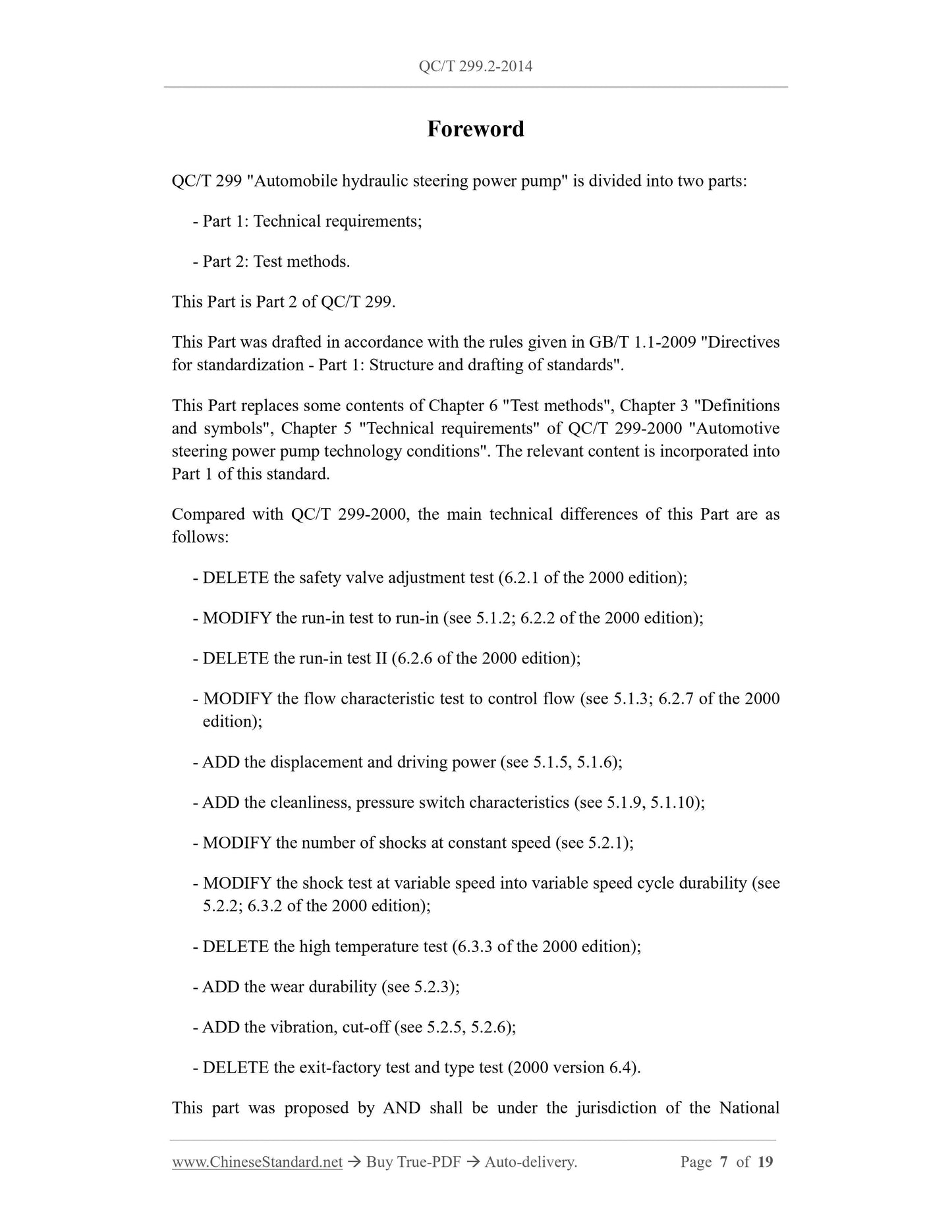
Foreword ... 7
1 Scope ... 9
2 Normative references ... 9
3 Terms and definitions ... 9
4 General requirements ... 9
5 Test method ... 10
Automobile hydraulic steering power pump - Part 2: Test
method
1 Scope
This Part of QC/T 299 specifies the bench test method for automotive hydraulic steering
power pumps.
This Part is applicable to invariable flow pumps (hereinafter referred to as steering
pumps) in conventional hydraulic power steering systems for automobiles, such as
steering vane pumps and steering gear pumps.
2 Normative references
The following documents are essential to the application of this document. For the dated
documents, only the versions with the dates indicated are applicable to this document;
for the undated documents, only the latest version (including all the amendments) is
applicable to this standard.
GB/T 5179 Automobile steering system - Terms and definitions
GB/T 14039 Hydraulic fluid power - Fluids - Method for coding the level of
contamination by solid particles
GB/T 20082 Hydraulic fluid power - Fluid contamination - Determination of
particulate contamination by the counting method using an optical microscope
QC/T 299.1 Automobile hydraulic steering power pump - Part 1: Technical
requirements
3 Terms and definitions
The terms and definitions, which are defined in GB/T 5179 and QC/T 299.1, apply to
this standard.
4 General requirements
4.1 The oil used for the test shall meet the requirements of the manufacturer. The oil
temperature for the performance test shall be (50 ± 5) °C.
4.2 The installation of the steering pump shall conform to the actual use condition.
4.3 For the steering pump driven by the belt pulley, its belt tension and wrap angle shall
meet the requirements of the manufacturer.
4.4 The test error of the pressure, torque, flow, tachometer used in the test is not more
than ±0.5%; the test error of the barometer is not more than ±0.4%.
5 Test method
5.1 Performance test
5.1.1 Maximum pressure.
Start the steering pump under no-load pressure. Increase the speed to 1500 r/min.
Quickly close the output oil circuit, to make the output flow zero. Keep it for 2 s ~ 3 s.
At this time, the stable pressure value is the opening pressure of the safety valve, that
is, the maximum pressure.
5.1.2 Run-in.
Start the steering pump under the no-load pressure. Increase the speed to the highest
speed nmax and keep it for 10 s. Then adjust the speed to 1500 r/min. Start from the no-
load pressure and increase the pressure step by step to 0.5Pmax, 0.85Pmax working
pressure, which is kept for 30 s, respectively.
5.1.3 Control flow.
5.1.3.1 No-load control flow.
Start the steering pump under no-load pressure. Measure the output flow, at different
speeds, from the lowest speed nmin to the highest speed nmax. The detection interval is
not more than 10 r/min. Draw the control flow characteristic curve. According to the
overall trend of the flow characteristic curve, find out the inflection point of the flow
curve, before and after the opening of the flow control valve. The speed and flow
corresponding to this inflection point are taken as the no-load opening speed n1k and
the no-load opening flow Q1k.
5.1.3.2 Load control flow.
Start the steering pump under no-load pressure. Adjust the pressure to 0.6Pmax working
pressure, when the speed rises to the minimum speed nmin. Measure the output flow, at
different speeds from the minimum speed nmin to 0.65nmax speed. The detection interval
is not more than 10 r/min. Draw the control flow characteristic curve. According to the
overall trend of the flow characteristic curve, find the inflection point of the flow curve,
before and after the flow control valve is opened. The speed and flow corresponding to
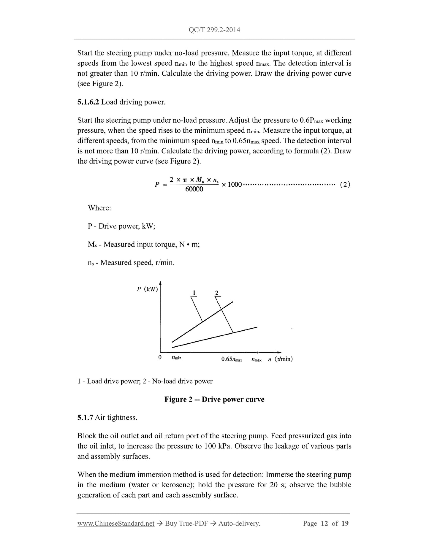
When the pressure drop method is used for detection: Cut off the gas feeding circuit;
measure the drop value of the inner chamber air pressure of the steering pump, within
10 s.
5.1.8 Noise.
The noise is measured at a rotational speed of 1000 r/min and a specified working
pressure. The background noise shall not exceed 55 dB(A). The sound level meter probe
shall be on the axis of the steering pump under test, which is 150 mm away from the
rear end face of the steering pump.
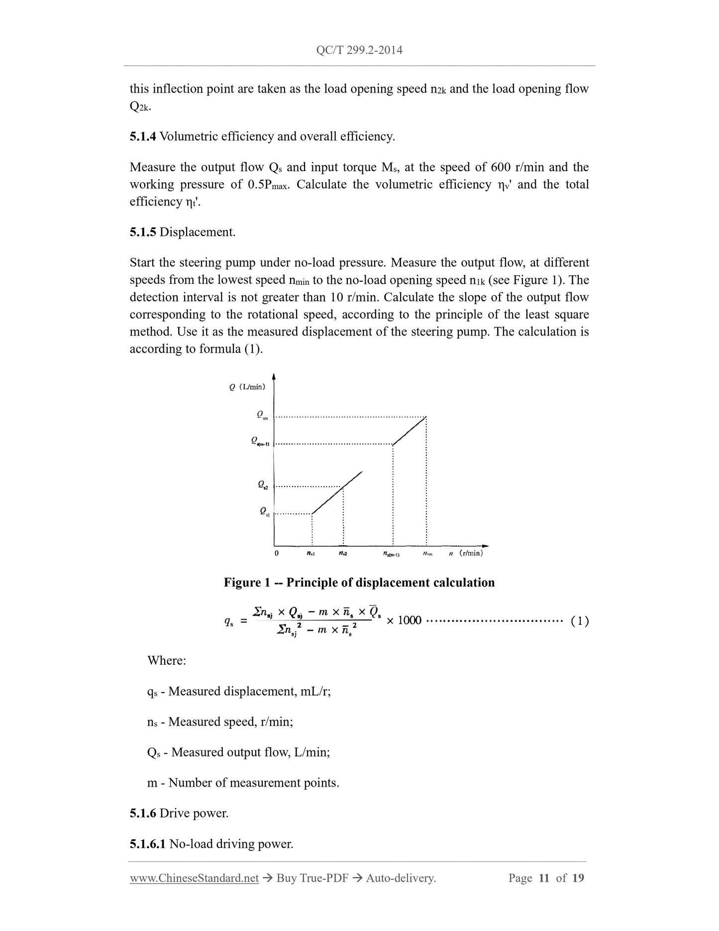
5.1.9 Cleanliness.
5.1.9.1 Extraction of impurities.
Inject a certain amount (accounting for 2/3 of the volume of the inner cavity) of the
cleaning test liquid, into the inner cavity of the steering pump. Seal the oil inlet, the oil
outlet, the oil return port. Use the method of vibration, to wash the internal impurities
into the test liquid. Then pour all the test fluid from the inner chamber of the steering
pump into the measuring cylinder. Repeat this for not less than 3 times. Read the total
liquid sample volume. The selection of cleaning test solution is as shown in Table 1.
Note: For special cleaning oil, clean gasoline or No.120 solvent oil is recommended, except for
special product requirements.
5.1.9.2 Weighing method.
Carry out vacuum filtration and filter membrane drying for the collected liquid samples.
The method shall be carried out, according to GB/T 20082. Then use the balance to
weigh the mass of impurities
5.1.9.3 Microscopy.
Carry out vacuum filtration and filter membrane drying for the collected liquid samples.
Use an optical microscope, to count the number of particles, which have a particle size
greater than or equal to 5 μm and greater than or equal to 15 μm. Calculate the total
number of particles, according to formula (3). The method is in accordance with GB/T
20082.
The total number of particles in GB/T 20082 is expressed by the number of particles,
which are greater than or equal to the selected size per 100 mL of liquid sample.
Where:
N - The number of particles greater than or equal to the selected size per 100 mL of
liquid sample;
A - The effective filtration area of the filter membrane, mm2;
n - The number of particles greater than or equal to the selected size;
105 - The factor used in the normative unit;
f - Number of cells counted;
L - The length of the counting unit, mm;
W - The width of the counting unit, mm;
V - Liquid sample volume, mL.
In order to be consistent with the expression of solid particle pollution levels in GB/T
14039, the number of particles greater than or equal to the selected size per 100 mL of
liquid sample is converted to the number of particles greater than or equal to the selected
size per milliliter of wet volume of the steering pump, according to formula (4).
Where:
N' - The number of particles, which are greater than or equal to the selected size per
milliliter of wet volume of the steering pump;
N - The number of particles, which are greater than or equal to the selected size per
100 mL of liquid sample;
V - Liquid sample volume, mL;
v - Wet volume of the inner cavity of the steering pump (take the theoretical
displacement q of the steering pump), mL.
5.1.9.4 Automatic particle counting method.
The collected liquid sample is fully precipitated. The solution on the liquid surface is
sucked up by...
Get QUOTATION in 1-minute: Click QC/T 299.2-2014
Historical versions: QC/T 299.2-2014
Preview True-PDF (Reload/Scroll if blank)
QC/T 299.2-2014: Automobile hydraulic steering power pump. Part 2: Test method
QC/T 299.2-2014
QC
AUTOMOBILE INDUSTRY STANDARD
OF THE PEOPLE’S REPUBLIC OF CHINA
ICS 43.040.50
T 23
Replacing QC/T 299-2000
Automobile hydraulic steering power pump - Part 2: Test
method
ISSUED ON: MAY 06, 2014
IMPLEMENTED ON: OCTOBER 01, 2014
Issued by: Ministry of Industry and Information Technology of PRC
Table of Contents
Foreword ... 7
1 Scope ... 9
2 Normative references ... 9
3 Terms and definitions ... 9
4 General requirements ... 9
5 Test method ... 10
Automobile hydraulic steering power pump - Part 2: Test
method
1 Scope
This Part of QC/T 299 specifies the bench test method for automotive hydraulic steering
power pumps.
This Part is applicable to invariable flow pumps (hereinafter referred to as steering
pumps) in conventional hydraulic power steering systems for automobiles, such as
steering vane pumps and steering gear pumps.
2 Normative references
The following documents are essential to the application of this document. For the dated
documents, only the versions with the dates indicated are applicable to this document;
for the undated documents, only the latest version (including all the amendments) is
applicable to this standard.
GB/T 5179 Automobile steering system - Terms and definitions
GB/T 14039 Hydraulic fluid power - Fluids - Method for coding the level of
contamination by solid particles
GB/T 20082 Hydraulic fluid power - Fluid contamination - Determination of
particulate contamination by the counting method using an optical microscope
QC/T 299.1 Automobile hydraulic steering power pump - Part 1: Technical
requirements
3 Terms and definitions
The terms and definitions, which are defined in GB/T 5179 and QC/T 299.1, apply to
this standard.
4 General requirements
4.1 The oil used for the test shall meet the requirements of the manufacturer. The oil
temperature for the performance test shall be (50 ± 5) °C.
4.2 The installation of the steering pump shall conform to the actual use condition.
4.3 For the steering pump driven by the belt pulley, its belt tension and wrap angle shall
meet the requirements of the manufacturer.
4.4 The test error of the pressure, torque, flow, tachometer used in the test is not more
than ±0.5%; the test error of the barometer is not more than ±0.4%.
5 Test method
5.1 Performance test
5.1.1 Maximum pressure.
Start the steering pump under no-load pressure. Increase the speed to 1500 r/min.
Quickly close the output oil circuit, to make the output flow zero. Keep it for 2 s ~ 3 s.
At this time, the stable pressure value is the opening pressure of the safety valve, that
is, the maximum pressure.
5.1.2 Run-in.
Start the steering pump under the no-load pressure. Increase the speed to the highest
speed nmax and keep it for 10 s. Then adjust the speed to 1500 r/min. Start from the no-
load pressure and increase the pressure step by step to 0.5Pmax, 0.85Pmax working
pressure, which is kept for 30 s, respectively.
5.1.3 Control flow.
5.1.3.1 No-load control flow.
Start the steering pump under no-load pressure. Measure the output flow, at different
speeds, from the lowest speed nmin to the highest speed nmax. The detection interval is
not more than 10 r/min. Draw the control flow characteristic curve. According to the
overall trend of the flow characteristic curve, find out the inflection point of the flow
curve, before and after the opening of the flow control valve. The speed and flow
corresponding to this inflection point are taken as the no-load opening speed n1k and
the no-load opening flow Q1k.
5.1.3.2 Load control flow.
Start the steering pump under no-load pressure. Adjust the pressure to 0.6Pmax working
pressure, when the speed rises to the minimum speed nmin. Measure the output flow, at
different speeds from the minimum speed nmin to 0.65nmax speed. The detection interval
is not more than 10 r/min. Draw the control flow characteristic curve. According to the
overall trend of the flow characteristic curve, find the inflection point of the flow curve,
before and after the flow control valve is opened. The speed and flow corresponding to
When the pressure drop method is used for detection: Cut off the gas feeding circuit;
measure the drop value of the inner chamber air pressure of the steering pump, within
10 s.
5.1.8 Noise.
The noise is measured at a rotational speed of 1000 r/min and a specified working
pressure. The background noise shall not exceed 55 dB(A). The sound level meter probe
shall be on the axis of the steering pump under test, which is 150 mm away from the
rear end face of the steering pump.
5.1.9 Cleanliness.
5.1.9.1 Extraction of impurities.
Inject a certain amount (accounting for 2/3 of the volume of the inner cavity) of the
cleaning test liquid, into the inner cavity of the steering pump. Seal the oil inlet, the oil
outlet, the oil return port. Use the method of vibration, to wash the internal impurities
into the test liquid. Then pour all the test fluid from the inner chamber of the steering
pump into the measuring cylinder. Repeat this for not less than 3 times. Read the total
liquid sample volume. The selection of cleaning test solution is as shown in Table 1.
Note: For special cleaning oil, clean gasoline or No.120 solvent oil is recommended, except for
special product requirements.
5.1.9.2 Weighing method.
Carry out vacuum filtration and filter membrane drying for the collected liquid samples.
The method shall be carried out, according to GB/T 20082. Then use the balance to
weigh the mass of impurities
5.1.9.3 Microscopy.
Carry out vacuum filtration and filter membrane drying for the collected liquid samples.
Use an optical microscope, to count the number of particles, which have a particle size
greater than or equal to 5 μm and greater than or equal to 15 μm. Calculate the total
number of particles, according to formula (3). The method is in accordance with GB/T
20082.
The total number of particles in GB/T 20082 is expressed by the number of particles,
which are greater than or equal to the selected size per 100 mL of liquid sample.
Where:
N - The number of particles greater than or equal to the selected size per 100 mL of
liquid sample;
A - The effective filtration area of the filter membrane, mm2;
n - The number of particles greater than or equal to the selected size;
105 - The factor used in the normative unit;
f - Number of cells counted;
L - The length of the counting unit, mm;
W - The width of the counting unit, mm;
V - Liquid sample volume, mL.
In order to be consistent with the expression of solid particle pollution levels in GB/T
14039, the number of particles greater than or equal to the selected size per 100 mL of
liquid sample is converted to the number of particles greater than or equal to the selected
size per milliliter of wet volume of the steering pump, according to formula (4).
Where:
N' - The number of particles, which are greater than or equal to the selected size per
milliliter of wet volume of the steering pump;
N - The number of particles, which are greater than or equal to the selected size per
100 mL of liquid sample;
V - Liquid sample volume, mL;
v - Wet volume of the inner cavity of the steering pump (take the theoretical
displacement q of the steering pump), mL.
5.1.9.4 Automatic particle counting method.
The collected liquid sample is fully precipitated. The solution on the liquid surface is
sucked up by...
Share